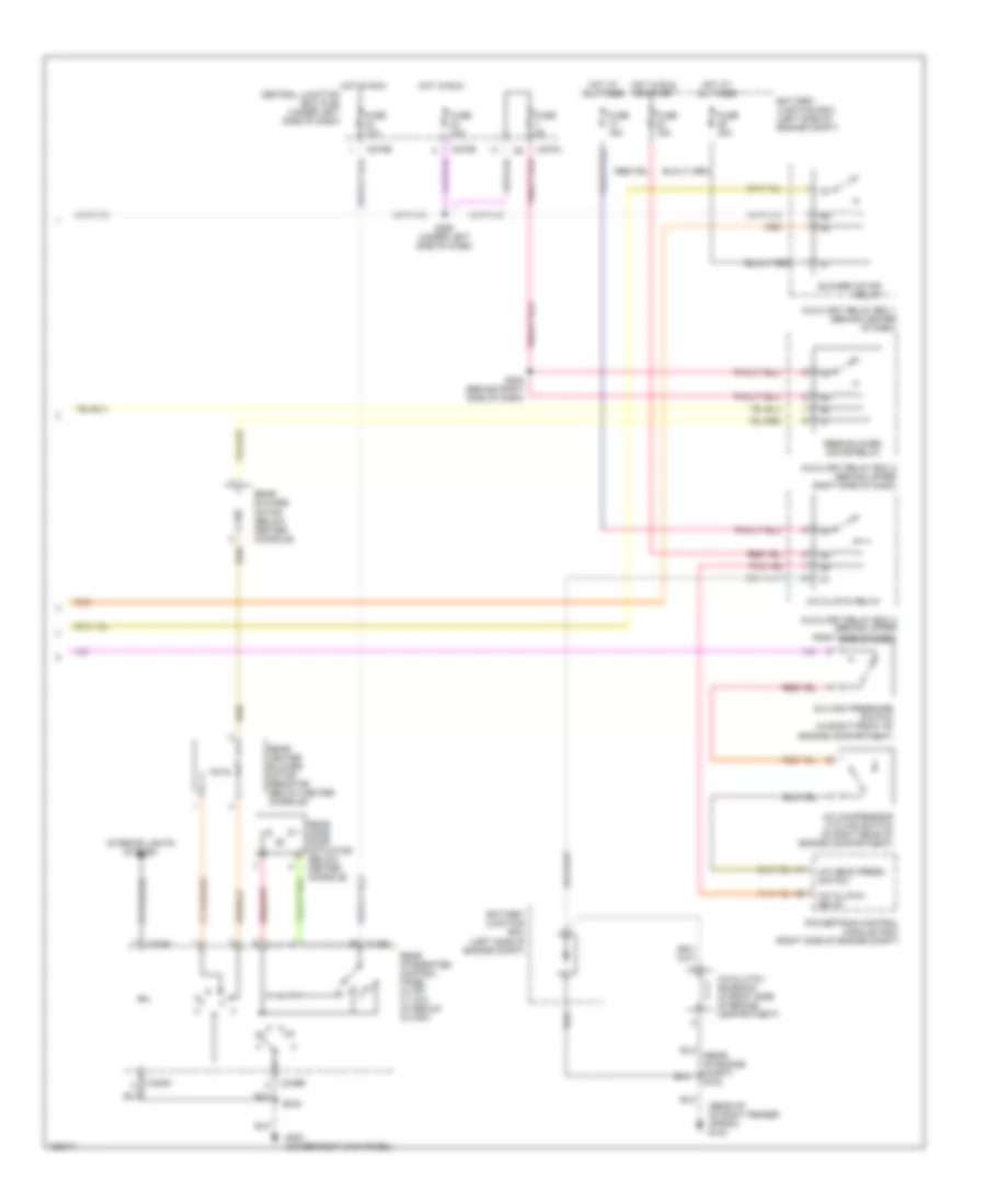
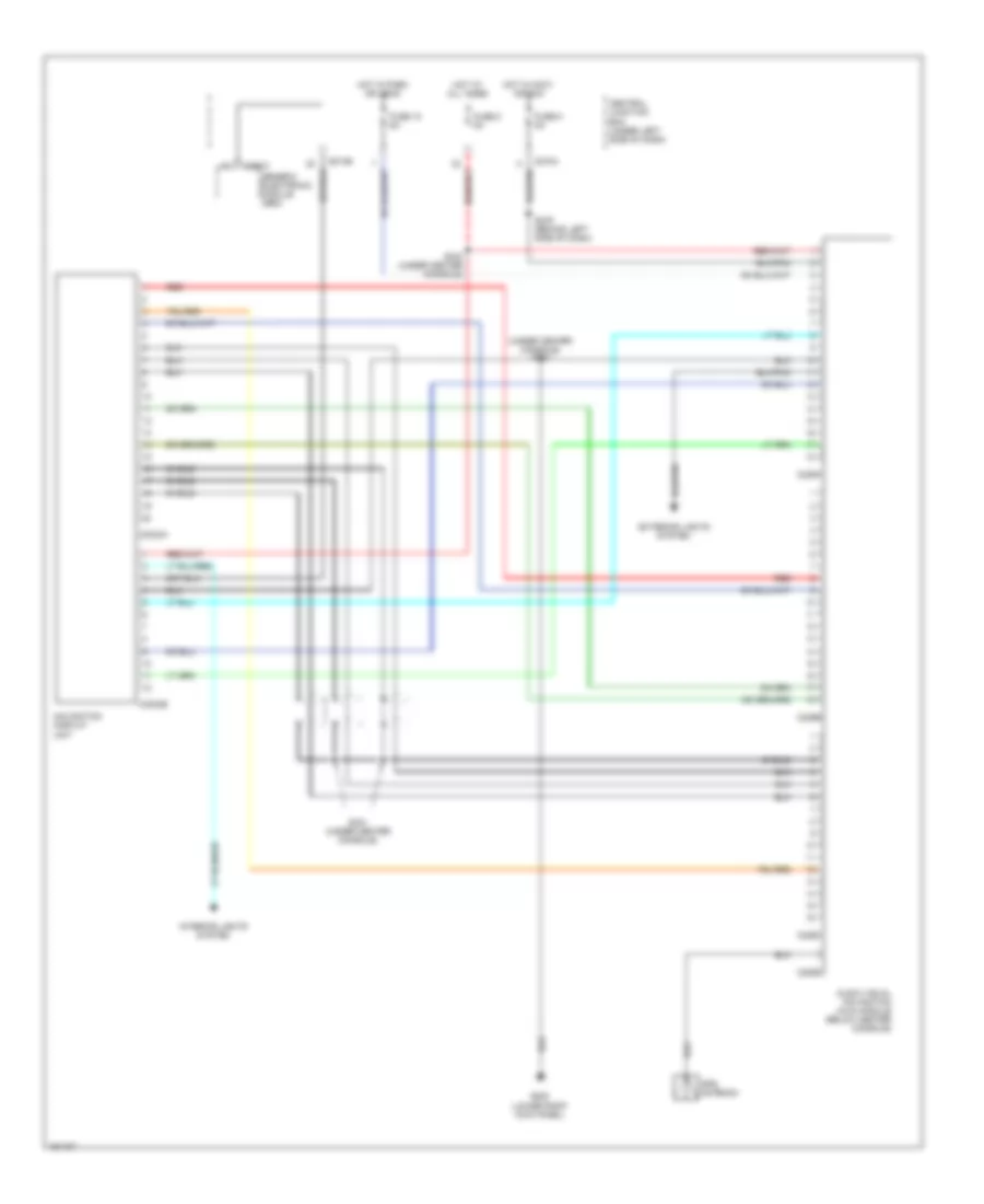
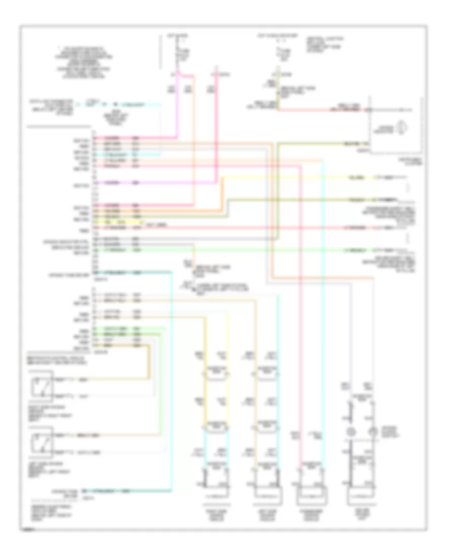
AIR CONDITIONING
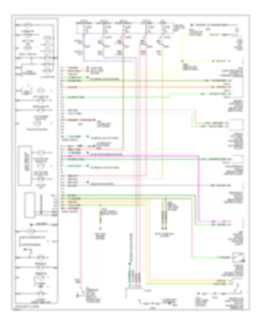
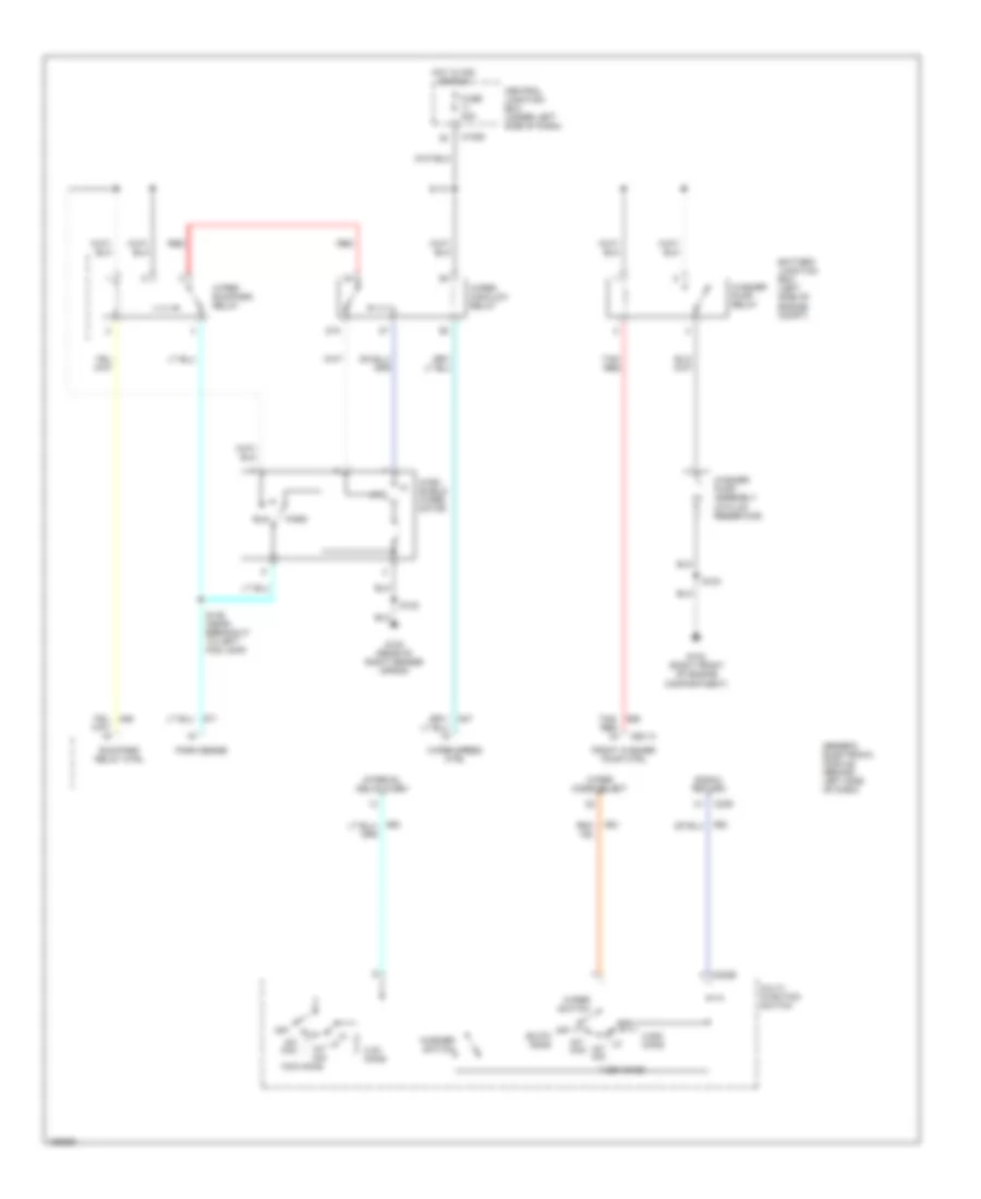
Automatic A/C Wiring Diagram (1 of 2) for Lincoln Blackwood 2003
 https://portal-diagnostov.com/license.html
Automotive Electricians Portal FZCO
Automotive Electricians Portal FZCO
https://portal-diagnostov.com/license.html
https://portal-diagnostov.com/license.html
Automotive Electricians Portal FZCO
Automotive Electricians Portal FZCO
List of elements for Automatic A/C Wiring Diagram (1 of 2) for Lincoln Blackwood 2003:
- 2.94 k ohms
- A/c demand signal
- Air bag sliding contact
- Ambient air sensor input
- Ambient air temperature sensor (right front of engine compt)
- Bat
- Blend door power
- Blend door ref voltage
- Blend door signal
- Blend door, power
- Blend door, sensor return
- Blower motor relay control
- C228a
- C228b
- C270a
- C271a
- C271b
- Central junction box (under left side of dash)
- Data link connector (dlc) (below left center of dash)
- Electronic automatic temperature control (eatc) module (behind center of dash)
- Fan speed (+)
- Fan speed (-)
- Front blower motor speed controller
- Fuse 5a
- G200 (lower right kick panel)
- Gnd
- Ground
- Heater blower motor
- Hot at all times
- Illumination
- In car temp sensor input
- In-vehicle temperature sensor (behind center of dash)
- Interior
- Interior lights system
- Lights system
- Ohms
- Rear blower relay control
- S200
- S236 (behind left side of dash)
- S276 (left side of dash)
- S277 (left side of dash)
- S286 (behind center of dash)
- Scp bus +
- Scp bus -
- Sensor sig return
- Signal
- Speed control servo (left side of engine compt)
- Speed controller, sig
- Steering wheel controls
- Steering wheel radio switch
- Sunload sensor
- Sunload sensor (top right side of dash)
- Switched gnd
- Temp (+)
- Temp (-)
- Temperature blend door actuator
- Vpwr
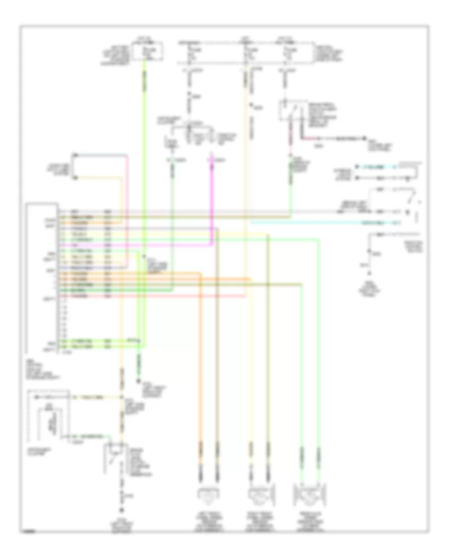
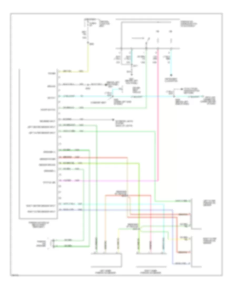
Automatic A/C Wiring Diagram (2 of 2) for Lincoln Blackwood 2003
List of elements for Automatic A/C Wiring Diagram (2 of 2) for Lincoln Blackwood 2003:
- (rear of engine compt) s102
- (rear of of right fender apron) g102
- A/c clutch relay
- A/c clutch solenoid (in right side of engine compartment)
- A/c compressor cycling switch (in right rear of engine compartment)
- A/c head press switch
- A/c high pressure switch (in right front of engine compartment)
- Auxiliary relay box 1 (behind center of dash)
- Auxiliary relay box 2 (behind upper right side of dash)
- Battery junction box (left side of engine compt)
- Blower motor relay
- C270a
- C270b
- C349a
- C349b
- Central junction box (cjb) (under left side of dash)
- Fuse 10a
- Fuse 15a
- Fuse 40a
- Fuse 5a
- G200 (lower right kick panel)
- Hot at all times
- Hot in run
- Hot in run or start
- Interior lights system
- Powertrain control module (pcm) (right side of engine compt)
- Rear blower motor (below center console)
- Rear blower motor relay
- Rear heater blower motor resistor (below center console)
- Rear integrated control panel (0) off (1) low (2) medium (3) high
- Rear mode door actuator (below center console)
- S283 (behind right side of dash)
- S292 (under left side of dash)
- S323
ANTI-LOCK BRAKES
Anti-lock Brakes Wiring Diagram for Lincoln Blackwood 2003
List of elements for Anti-lock Brakes Wiring Diagram for Lincoln Blackwood 2003:
- (behind left side of dash) s250
- Abs control module (on left side of engine compt)
- Anti- lock ind
- Battery junction box (on left side of engine compartment)
- Bias ckt
- Brake fluid level switch (on brake fluid reservoir)
- Brake pedal position (bpp) switch (above brake pedal, on bracket)
- C146
- C220a
- C243
- C270a
- C270b
- Central junction box (under left side of dash)
- Computer data lines system
- Fuse 10a
- Fuse 50a
- Fuse 5a
- G104 (left front radiator support)
- G200 (lower right kick panel)
- G201 (lower left kick panel)
- Gnd
- Hot at all times
- Hot in run
- Instrument cluster
- Interior lights system
- Left front wheel speed sensor (on steering hub assembly)
- Nca
- Ohm
- Processor micro-
- Rear axle speed sensor (dss) (on rear differential)
- Right front wheel speed sensor (on steering hub assembly)
- S106
- S160 (rear of engine compt)
- S170 (left side of engine compt)
- S171 (left side of engine compt)
- S172
- S202
- S208
- S228
- S265
- Scp+
- Scp-
- Tan/red
- Traction control ind
- Traction control switch
- Vbatt
- Vpwr
ANTI-THEFT
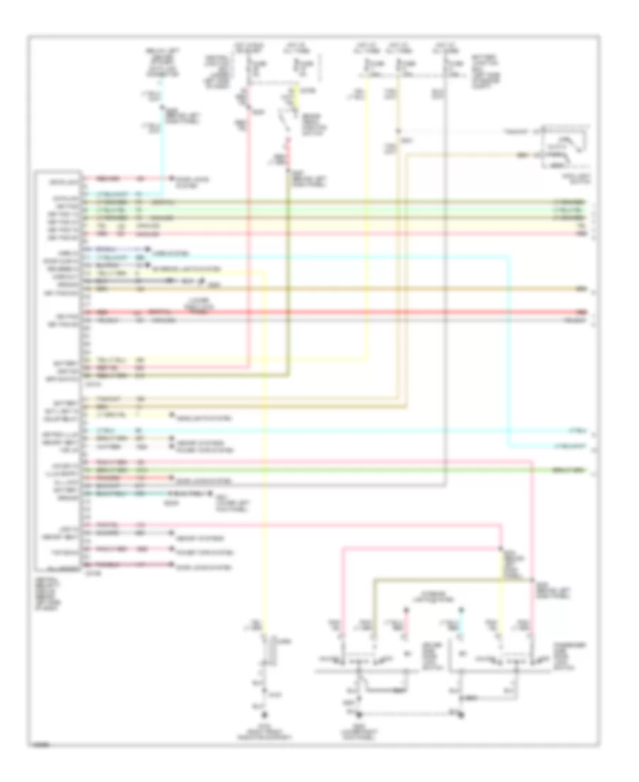
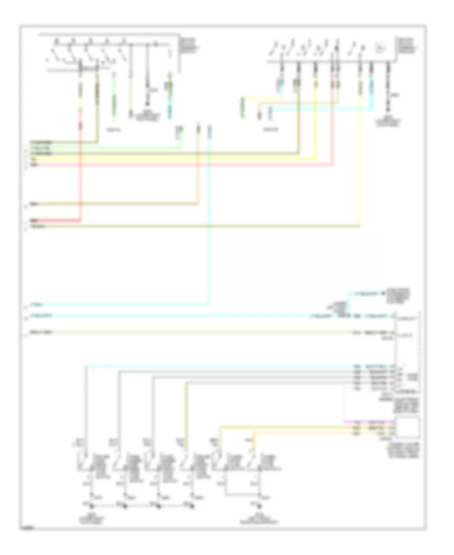
Forced Entry Wiring Diagram (1 of 2) for Lincoln Blackwood 2003
List of elements for Forced Entry Wiring Diagram (1 of 2) for Lincoln Blackwood 2003:
- (analog)
- (below left center of dash) data link connector
- (digital)
- (lower
- All lock
- All unlock
- Auto
- Battery
- Battery junction box (left side of engine compt)
- Bpp switch
- Brake pedal position switch
- C270b
- C274a
- C274b
- Central junction box (under left side of dash)
- Central security module (behind left side of dash)
- Datalink
- Door ajar in
- Door locks system
- Driver side door lock switch
- Drvr lock
- Ext light in
- Exterior lights system
- Fuse 15a
- Fuse 20a
- Fuse 30a
- Fuse 5a
- G103 (right front radiator support)
- G200
- G200 (lower right kick panel)
- G201 (lower left kick panel)
- Ground
- Hdlmp relay
- Head
- Headlights system
- Horn
- Horn in
- Horn out
- Horn system
- Hot at all times
- Hot in run or start
- Ignition
- Illum entry
- Interior lights system
- Key pad
- Key pad 1/2
- Key pad 3/4
- Key pad 5/6
- Key pad 7/8
- Key pad 9/0
- Key pad com
- Keypad illum
- Lock
- Lock in
- Main light switch
- Memory seat
- Memory systems
- Off
- Park
- Passenger side door lock switch
- Power tops system
- Red
- Reverse in
- Right kick panel)
- S103
- S2000
- S225
- S229 (behind left dash panel)
- S234 (behind left dash panel)
- S235 (behind left dash panel)
- S241
- S297 (behind left dash panel)
- S500
- S600
- Top down
- Top up
- Unlock
- Unlock in
Forced Entry Wiring Diagram (2 of 2) for Lincoln Blackwood 2003
List of elements for Forced Entry Wiring Diagram (2 of 2) for Lincoln Blackwood 2003:
- (under left dash panel) s262
- 1/2
- 3/4
- 5/6
- 7/8
- 9/0
- Ajar out
- Analog
- C201a
- C201b
- C4054c
- Cargo door ajar switch
- Cargo door ajar switch 2
- Digital
- Door ajar
- Driver side front door ajar switch
- Driver side rear door ajar switch
- Electronic suspension & steering systems
- G104 (left front radiator support)
- G200 (lower right kick panel)
- Generic electronic module (gem) (behind left side of dash)
- Illum in
- Keypad switch assembly (analog)
- Keypad switch assembly (digital)
- Liftgate
- Nca
- Pass- enger side front door ajar switch
- Pass- enger side rear door ajar switch
- Red
- S333
- S401
- S500
- S600
- S701
- S801
- Tan
- Tonneau cover control module (on right front of cargo area)
Passive Anti-theft Wiring Diagram for Lincoln Blackwood 2003
List of elements for Passive Anti-theft Wiring Diagram for Lincoln Blackwood 2003:
- Anti-theft indicator
- C220a
- C220b
- C252
- C270a
- C270b
- Central junction box (under left side of dash)
- Computer data lines system
- Fuse 30a
- Fuse 5a
- G201 (lower left kick panel)
- Hot in run
- Hot in run or start
- Instrument cluster
- Passive anti- theft system (pats) trans- ceiver module (behind center of dash)
- S208
- S237
- S265
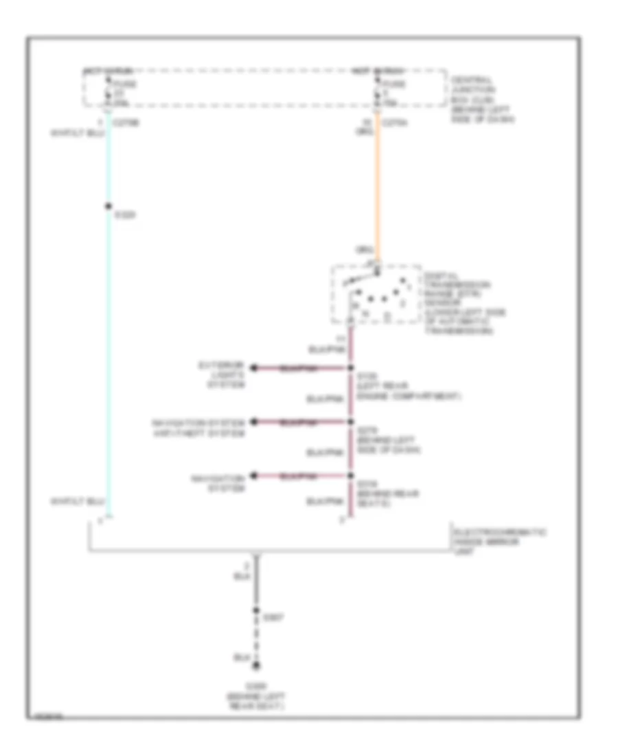
BODY CONTROL MODULES
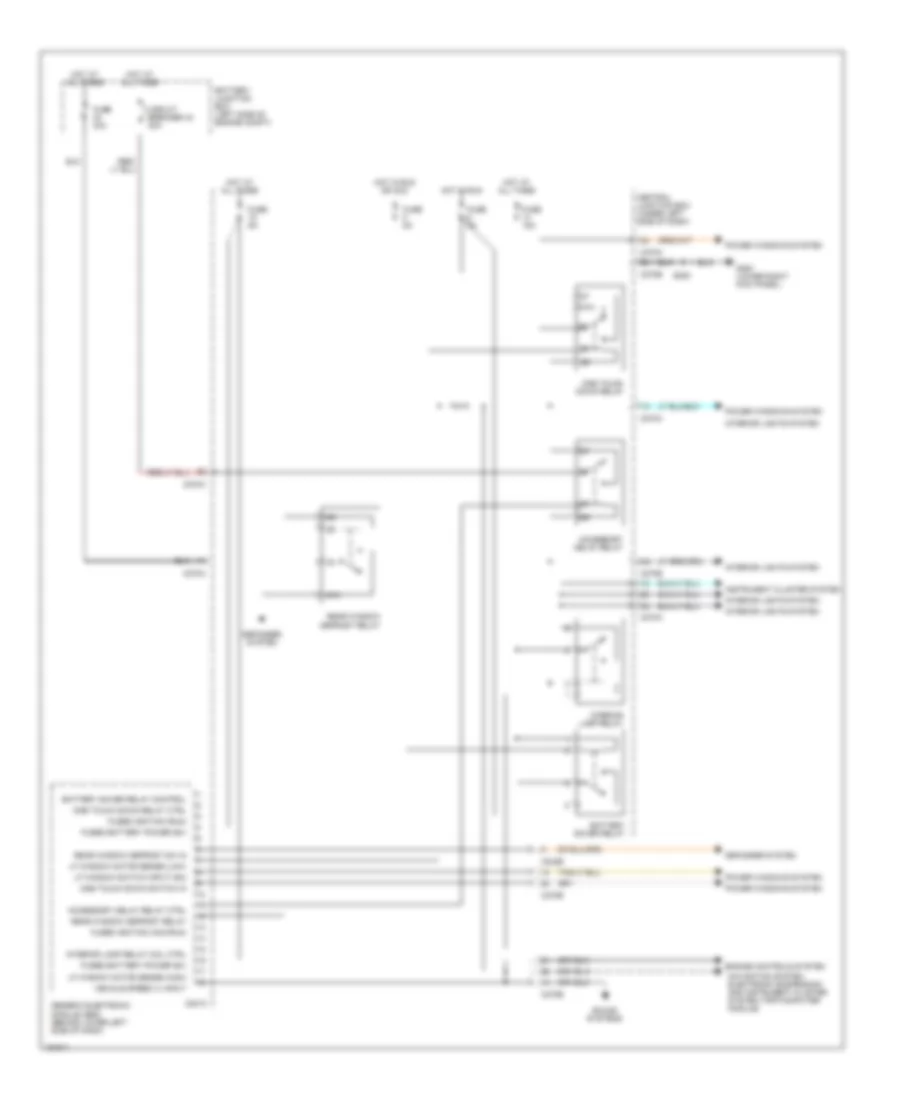
Body Control Modules Wiring Diagram (1 of 2) for Lincoln Blackwood 2003
List of elements for Body Control Modules Wiring Diagram (1 of 2) for Lincoln Blackwood 2003:
- 87a
- Accessory delay relay
- Accessory delay relay ctrl
- Battery junction box (left side of engine compt)
- Battery saver relay
- Battery saver relay control
- C201c
- C242b
- C270a
- C270b
- Central junction box (under left side of dash)
- Circuit breaker 43 30a
- Defogger system
- Engine controls system
- Fuse 15a
- Fuse 40a
- Fuse 5a
- Fused battery power (b+)
- Fused ignition (acc/run)
- Fused ignition (run)
- G200 (lower right kick panel)
- Generic electronic module (gem) (behind lower left side of dash)
- Hot at all times
- Hot in run
- Hot in run or acc
- Instrument cluster system
- Interior lamp relay
- Interior lamp relay coil ctrl
- Interior lights system
- Lf window motor sense (high)
- Lf window motor sense (low)
- Lf window switch input (dn)
- Navigation system, electronic suspension and instrument cluster system (trip computer module)
- One touch down relay
- One touch down relay ctrl
- One touch down switch in
- Power windows system
- Rear window defrost relay
- Rear window defrost sw in
- S205
- Sound systems
- Vehicle speed (+) input
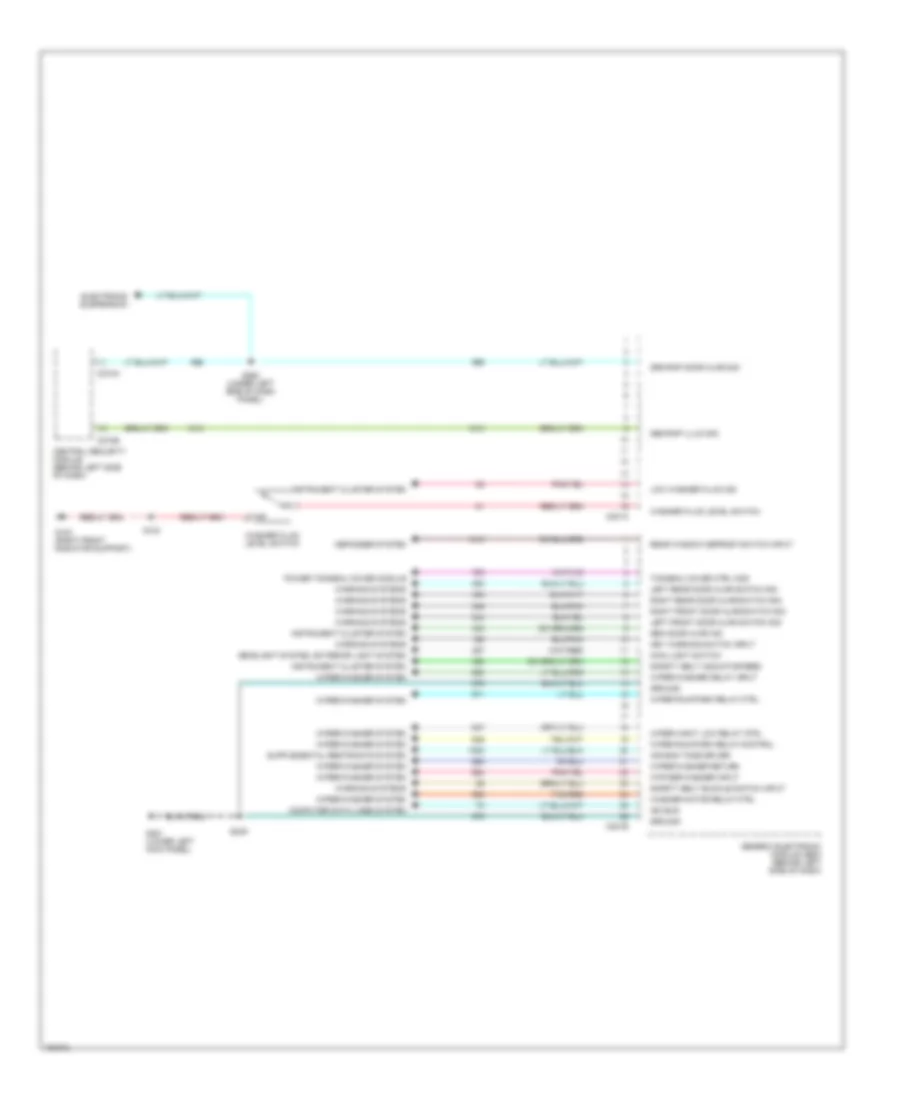
Body Control Modules Wiring Diagram (2 of 2) for Lincoln Blackwood 2003
List of elements for Body Control Modules Wiring Diagram (2 of 2) for Lincoln Blackwood 2003:
- Air bag tone driver
- C201a
- C201b
- C274a
- C274b
- Central security module (behind left side of dash)
- Computer data lines system
- Defogger system
- Electronis suspension
- G103 (right front radiator support)
- G201 (lower left kick panel)
- Gem door ajar ind
- Gem/rap illum sig
- Generic electronic module (gem) (behind left side of dash)
- Grm/rap door ajar sig
- Ground
- Headlight system, exterior light system
- Instrument cluster system
- Iso bus
- Key warning switch input
- Left front door ajar switch sig
- Left rear door ajar switch sig
- Low washer fluid ind
- Main light switch
- Power tonneau cover module
- Rear window defrost switch input
- Right front door ajar switch sig
- Right rear door ajar switch sig
- S103
- S249
- S262 (under left side of dash panel)
- Safety belt buckle switch input
- Safety belt indicator feed
- Tan/red
- Tonneau cover ctrl mod
- Warning systems
- Washer fluid level switch
- Washer motor relay ctrl
- Wiper hight low relay ctrl
- Wiper run/park relay control
- Wiper run/park relay ctrl
- Wiper/washer delay input
- Wiper/washer return
- Wiper/washer system
- Wipwer/washer input
COMPUTER DATA LINES
Computer Data Lines Wiring Diagram for Lincoln Blackwood 2003
List of elements for Computer Data Lines Wiring Diagram for Lincoln Blackwood 2003:
- (behind left side of dash) s229
- (below left center of dash) data link connector (dlc)
- (rear engine compt) s157
- (under left side of dash) s292
- Abs control module (left side of engine compt)
- Air suspension module (behind center of dash)
- C135
- C174
- C201a
- C2041a
- C2131a
- C220b
- C228b
- C270a
- C274a
- C341a
- C4054c
- Central juncton box (left side of dash)
- Central security module (behind left side of dash)
- Driver seat module (under driver seat) (w/memory seat)
- Electronic automatic temperature control module
- Fuse 20a
- G101 (center of firewall)
- G200 (lower right kick panel)
- Generic electronic module (gem) (behind left side of dash)
- Hot at all times
- Instrument cluster
- Parking aid module (right rear of vehicle)
- Powertrain control module (pcm) (right side of engine compt)
- Restraints control module (rcm) (behind right side of dash)
- S156 (rear engine compt)
- S202
- S276 (behind left side of dash)
- S277 (behind left side of dash)
- S289
- Tonneau cover control module (right front of cargo area)
CRUISE CONTROL
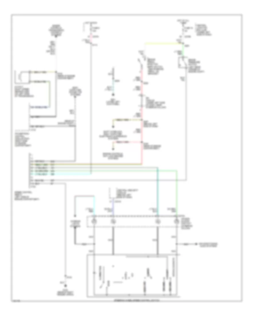
Cruise Control Wiring Diagram for Lincoln Blackwood 2003
List of elements for Cruise Control Wiring Diagram for Lincoln Blackwood 2003:
- (left rear corner of engine compt)
- (rear of engine compt) s143
- 120 ohms
- 15a
- 2200 ohms
- 680 ohms
- Air bag sliding contact (steering column)
- Air conditioning, audio systems
- Body computer, power top systems
- Brake pedal position (bpp) switch (above brake pedal, on bracket)
- Brake pressure switch
- C122
- C175
- C218a
- C270a
- C270b
- C274a
- Central junction box (cjb) (under left side of dash)
- Central security module (behind left side of dash)
- Coast
- Engine controls, anti-lock brakes systems
- Engine controls, transmission controls systems
- Fuse 15
- Fuse 5
- G102 (rear of right fender apron)
- G201 (lower left kick panel)
- Horn
- Hot at all times
- Hot in run
- Illumination
- Interior lights systems
- Nca
- Off
- Output shaft speed sensor (oss) (on left side of transmission)
- Powertrain control module (pcm) (right side of engine compartment)
- Resume
- Rfi module (under left side of dash, near steering column)
- S102
- S112
- S138 (rear of engine compartment)
- S160 (rear of engine compartment)
- S208
- S252
- S291
- S297 (behind left side of dash)
- Set/accelerate
- Shift interlock, body computer, electronic suspension systems
- Speed control servo (left side of engine compartment)
- Steering wheel/speed control switch
DEFOGGERS
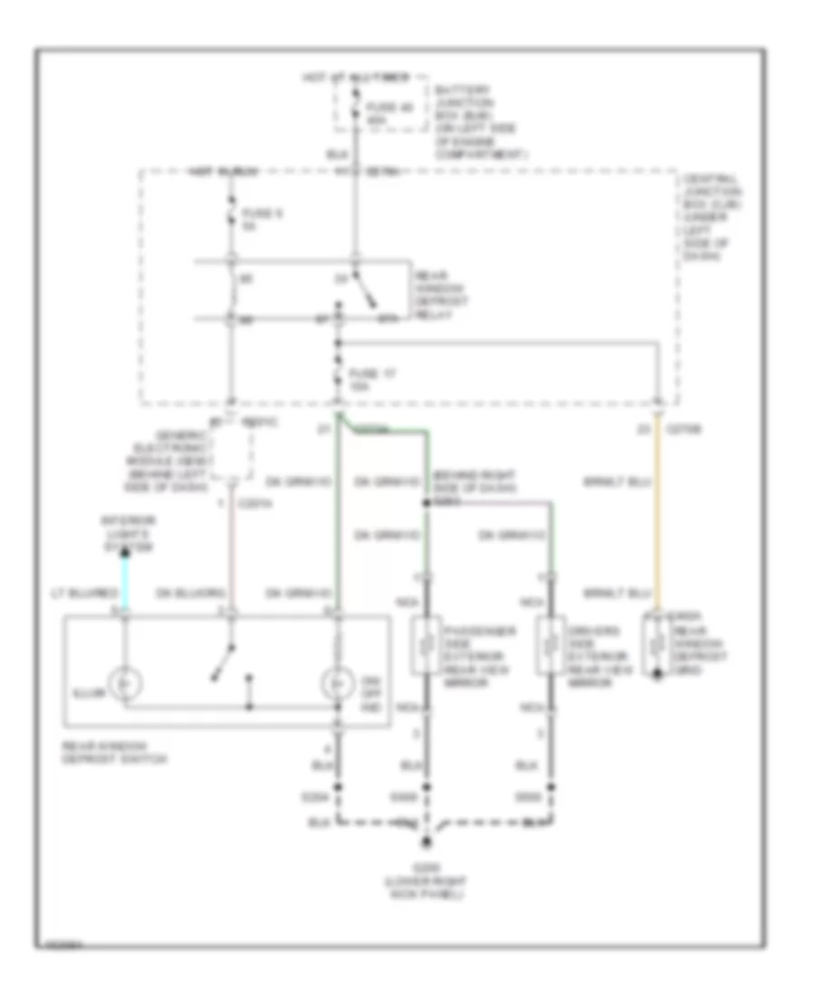
Defoggers Wiring Diagram for Lincoln Blackwood 2003
List of elements for Defoggers Wiring Diagram for Lincoln Blackwood 2003:
- 87a
- Battery junction box (bjb) (on left side of engine compartment)
- C201a
- C201c
- C270a
- C270b
- C402a
- Central junction box (cjb) (under left side of dash)
- Drivers side exterior rear view mirror
- Fuse 17 10a
- Fuse 40 40a
- Fuse 6 5a
- G200 (lower right kick panel)
- Generic electronic module (gem) (behind left side of dash)
- Hot at all times
- Hot in run
- Illum
- Interior lights system
- Nca
- On/ off ind
- Passenger side exterior rear view mirror
- Rear window defrost grid
- Rear window defrost relay
- Rear window defrost switch
- S204
- S500
- S600
ELECTRONIC POWER STEERING
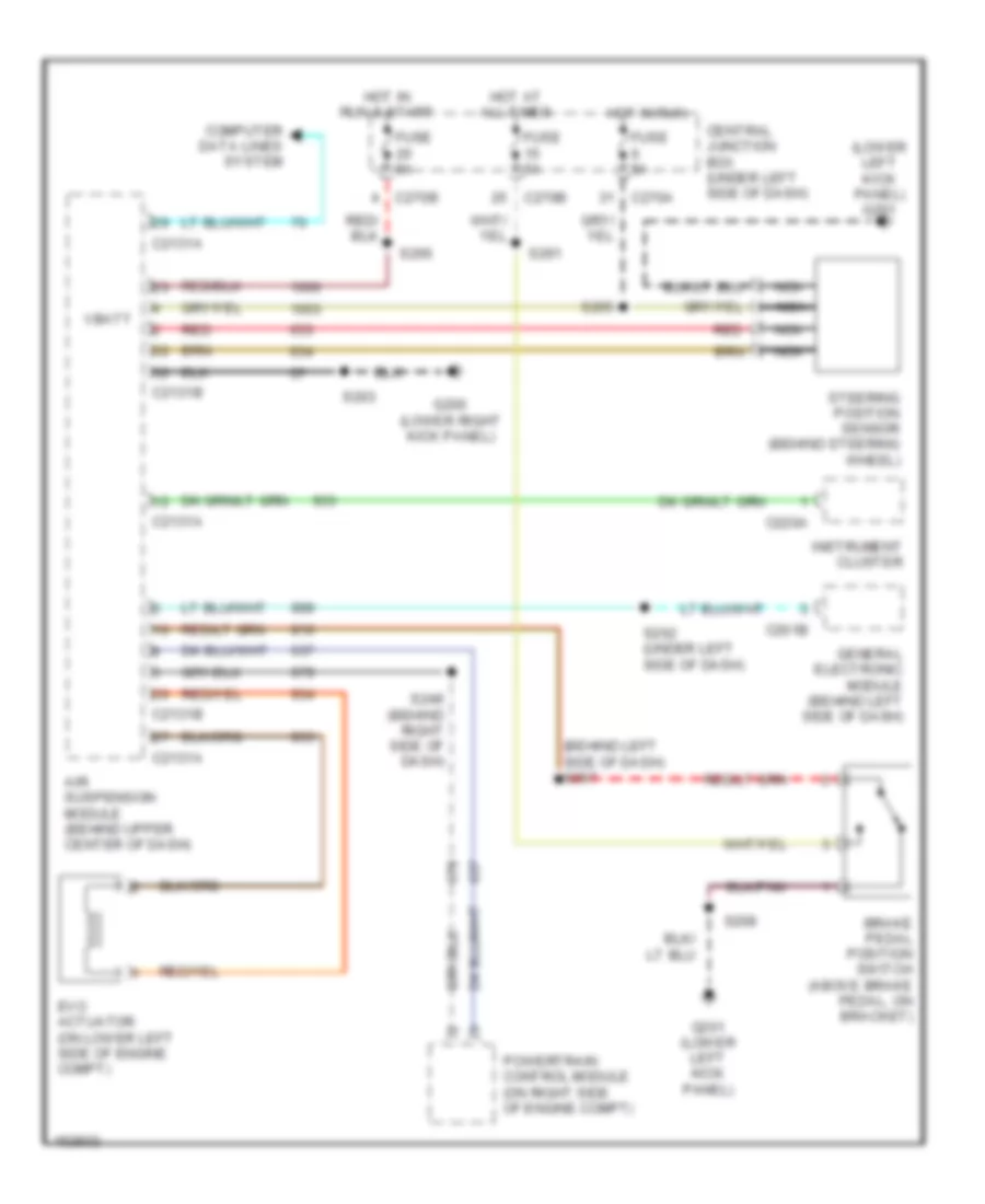
Electronic Power Steering Wiring Diagram for Lincoln Blackwood 2003
List of elements for Electronic Power Steering Wiring Diagram for Lincoln Blackwood 2003:
- (behind left side of dash) s297
- (lower left kick panel) g201
- Air suspension module (behind upper center of dash)
- Brake pedal position switch (above brake pedal, on bracket)
- C201b
- C2131a
- C2131b
- C220a
- C270a
- C270b
- Central junction box (under left side of dash)
- Computer data lines system
- Evo actuator (on lower left side of engine compt)
- Fuse 5a
- G200 (lower right kick panel)
- G201 (lower left kick panel)
- General electronic module (behind left side of dash)
- Hot at all times
- Hot in run
- Hot in run & start
- Instrument cluster
- Nca
- Powertrain control module (on right side of engine compt)
- Red
- S203
- S208
- S249 (behind right side of dash)
- S262 (under left side of dash)
- S265
- S266
- S291
- Steering position sensor (behind steering wheel)
- Vbatt
ELECTRONIC SUSPENSION
Electronic Suspension Wiring Diagram (1 of 2) for Lincoln Blackwood 2003
List of elements for Electronic Suspension Wiring Diagram (1 of 2) for Lincoln Blackwood 2003:
- (behind center of dash) s288
- (right front engine compt) air suspension compressor
- (right front engine compt) s107
- Air suspension indicator
- Air suspension module (behind upper center of dash)
- Air suspension service switch
- Air suspension solid state relay (near right headlamp)
- Battery junction box (left side of engine compt)
- C2131b
- C220a
- C270a
- C270b
- C2i31a
- Central junction box (under left side of dash)
- Computer data lines system
- Fuse 15a
- Fuse 50a
- Fuse 5a
- G103 (right front radiator support)
- G104 (left front radiator support)
- G200 (lower right kick panel)
- G201 (lower left kick panel)
- Hot at all times
- Hot in run
- Hot in start
- Instrument cluster
- Left rear shock absorber solenoid valve (above left rear shock absorber, on frame)
- Nca
- Pnk
- Right rear shock absorber solenoid valve (above right rear shock absorber, on frame)
- S103
- S263
- S291
- S400
- Solid state
Electronic Suspension Wiring Diagram (2 of 2) for Lincoln Blackwood 2003
List of elements for Electronic Suspension Wiring Diagram (2 of 2) for Lincoln Blackwood 2003:
- (behind right side of dash) s249
- (lower left kick panel)
- Air suspension height sensor (beneath rear of vehicle, near rear axle)
- Brake pedal position (bpp) switch (above brake pedal, on bracket)
- C175
- C201b
- Central junction box (under left side of dash)
- Fuse 5a
- G102 (rear of right fender apron)
- G201
- Generic electronic (gem) module (behind left side of dash)
- Generic electronic module (gem)
- Hot at all times
- Instrument cluster, navigation
- Powertrain control module (pcm) (right side of engine compt)
- S102
- S143 (rear of engine compt)
- S208
- S262 (under left side of dash)
- S291
- Side of dash)
- Speed control servo
ENGINE PERFORMANCE
5.4L
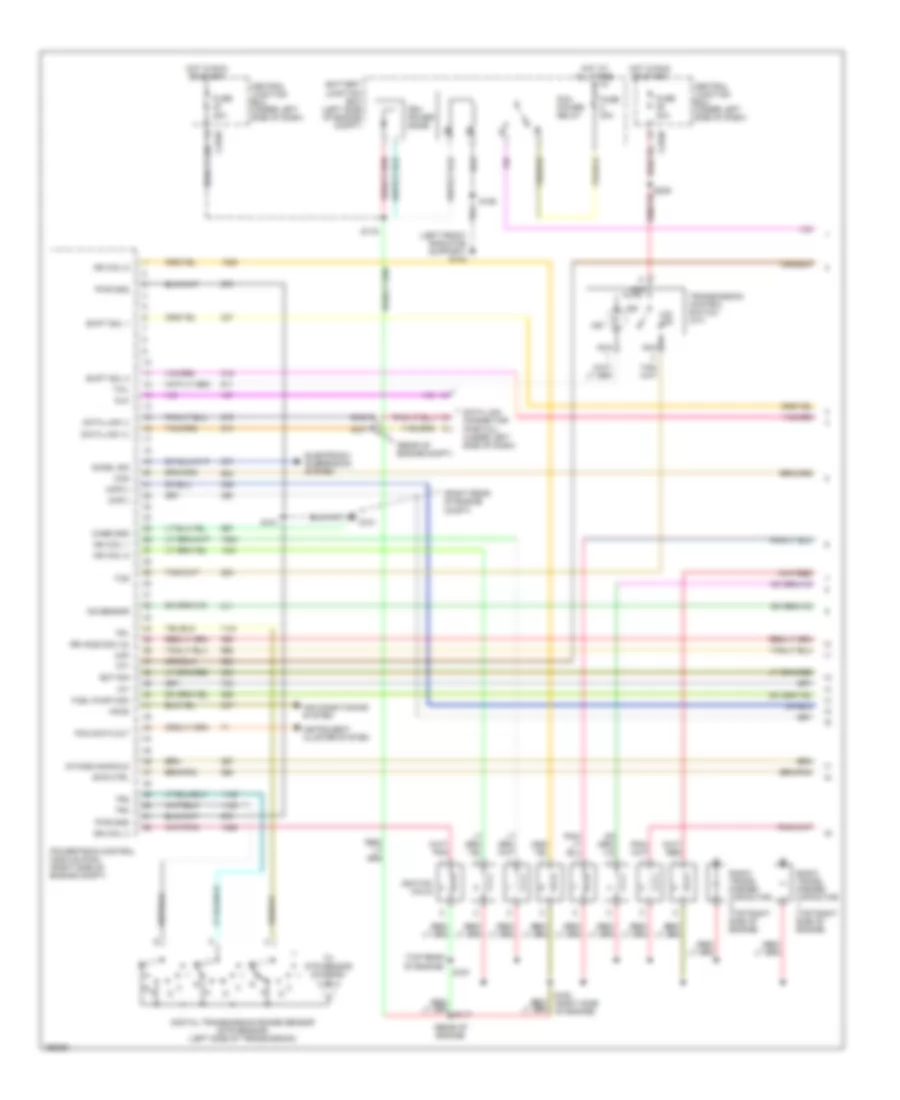
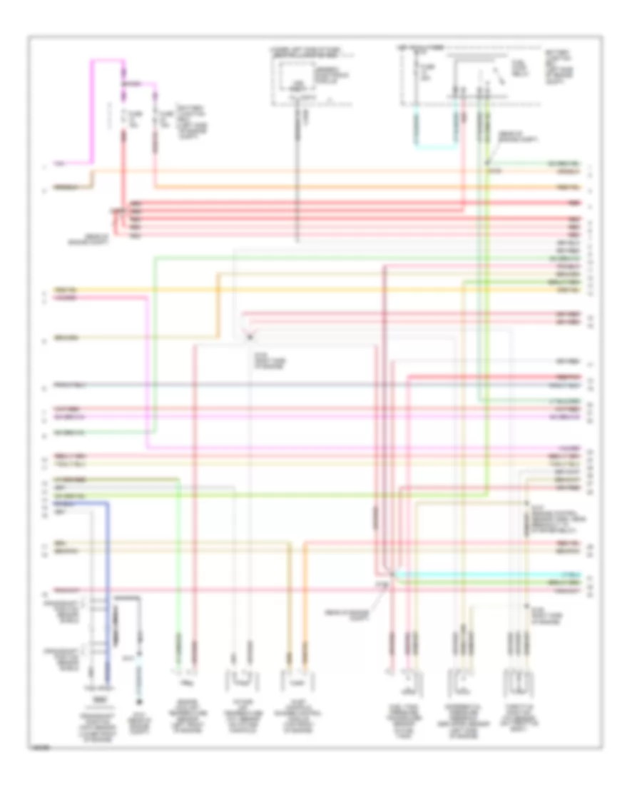
5.4L, Engine Performance Wiring Diagram (1 of 4) for Lincoln Blackwood 2003
List of elements for 5.4L, Engine Performance Wiring Diagram (1 of 4) for Lincoln Blackwood 2003:
- (left front radiator support) g104
- (rear of engine compt)
- (rear of engine)
- (right rear of engine compt)
- (top rear of engine)
- Accel sig
- Accs
- Air conditioning system
- Battery junction box (left side of engine compt)
- Case gnd
- Ccs
- Central junction box (under left side of dash)
- Ckp(+)
- Ckp(-)
- Data link (+)
- Data link (-)
- Data link connector (partial) (under left side of dash)
- Digital transmission range sensor (dtr sensor) (left side of transmission)
- Dlc
- Ect sig
- Electronic suspension system
- Evr ctrl
- Fuel pump mon
- Fuse 30a
- G101
- Hot at all times
- Hot in run or start
- Iat
- Ign coil 1
- Ign coil 3
- Ign coil 5
- Ign coil 6
- Ignition coils
- Ind
- Instrument cluster system
- Intake manifold
- Ks sensor
- Maf
- Nca
- O/d off
- Pcm data out
- Pcm power diode
- Pcm power relay
- Powertrain control module (pcm) (right side of engine compt)
- Pwr gnd
- R n
- Radio trans- former capacitor (top right side of engine)
- Rr ho2s sig (12)
- S101
- S106
- S116
- S156
- S157
- S161
- S162 (right side of engine)
- Shift sol 1
- Shift sol 2
- Tcil
- Tcs
- Tft
- To dtr sensor (diagram 4 of 4)
- Tr1
- Tr2
- Tr4
- Transmission control switch (a/t)
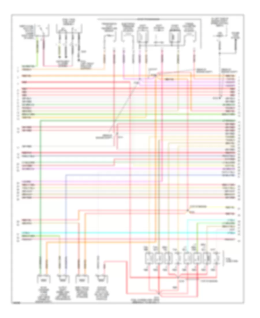
5.4L, Engine Performance Wiring Diagram (2 of 4) for Lincoln Blackwood 2003
List of elements for 5.4L, Engine Performance Wiring Diagram (2 of 4) for Lincoln Blackwood 2003:
- (rear of engine compt)
- (under left side of dash) central junction box
- Battery junction box (left side of engine compt)
- C201c
- Crankshaft position (ckp) sensor (lower front of engine)
- Crankshaft position sensor shield
- Differential pressure feedback egr (dpfe) sensor (left side of engine)
- Engine coolant temperature sensor (left front of engine)
- Fuel pump relay
- Fuel tank pressure transducer sensor (in fuel tank)
- Fuse 15a
- Fuse 20a
- G101 (rear of engine compt)
- Generic electronic module
- Hot at all times
- Inlet manifold runner control module (top front of engine)
- Intake air temperature (iat) sensor (on intake manifold)
- Nca
- Red
- Red/pnk
- S1003
- S101
- S127
- S135 (right side of engine)
- S136 (right side of engine)
- S137 (engine control sensor harn, near breakout to starter relay)
- S138
- S139
- Throttle position (tp) sensor (on throttle body)
- Vss input
5.4L, Engine Performance Wiring Diagram (3 of 4) for Lincoln Blackwood 2003
List of elements for 5.4L, Engine Performance Wiring Diagram (3 of 4) for Lincoln Blackwood 2003:
- (fuel tank) fuel pump assembly
- (in left side of engine compt) speed control servo
- (rear of engine compt)
- (top of engine)
- 4r100 transmission
- Coast clutch solenoid
- Egr vacuum regulator solenoid (left side of engine)
- Electronic pressure control solenoid
- Evap canister purge
- Fuel injectors
- G104 (left front radiator support)
- Idle air control (iac) valve (on left side of intake manifold)
- Instrument cluster system
- Nca
- Output shaft speed (oss) sensor (left side of transmission)
- Power tops system
- Red
- Red/pnk
- S129
- S131 (fuel charge harn, near breakout to ign coil 7)
- S140
- S141
- S143
- S154
- S155
- S400
- Shift solenoid a
- Shift solenoid b
- Tan
- Tan/ red
- Tan/red
- Torque converter clutch solenoid
- Transmission fluid temperature sensor
- Valve (left rear corner of engine compt)
- Vss input
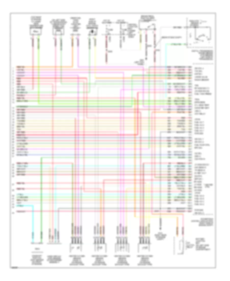
5.4L, Engine Performance Wiring Diagram (4 of 4) for Lincoln Blackwood 2003
List of elements for 5.4L, Engine Performance Wiring Diagram (4 of 4) for Lincoln Blackwood 2003:
- (near fuel tank) evap canister vent valve
- (on left side of engine compartment)
- (on left side of transmission) turbine shaft speed (tss) sensor
- (rear of eng compt)
- (right side of engine) dual knock sensor (ks)
- (top front of engine) cylinder head temperature (cht) sensor
- 5v ref volt
- A/c clutch relay
- Battery junction box
- Bpp sw
- Brake pedal position (bpp) switch
- Cam pos in
- Camshaft position (cmp) sensor (on front of engine)
- Canister vent
- Central junction box (under left side of dash)
- Cyl head temp
- Digital transmission range sensor (dtr sensor) (left side of transmission)
- Dpfe sens
- Epc sol
- From dtr sensor (diagram 1 of 4)
- Fuel inj 1
- Fuel inj 2
- Fuel inj 3
- Fuel inj 4
- Fuel inj 5
- Fuel inj 6
- Fuel inj 7
- Fuel inj 8
- Fuel pump ctrl
- Fuel tank press
- Fuse 5a
- G101 (right rear of engine compt)
- G201 (left kick panel)
- Heated oxygen sensor (ho2s) 11 (on engine exhaust pipe)
- Heated oxygen sensor (ho2s) 12 (on engine exhaust pipe)
- Heated oxygen sensor (ho2s) 21 (on engine exhaust pipe)
- Heated oxygen sensor (ho2s) 22 (on engine exhaust pipe)
- Heater ctrl
- Hot at all times
- Iac sol
- Ign coil 2
- Ign coil 4
- Ign coil 7
- Ign coil 8
- Kap b(+)
- Knock sensor
- Lf ho2s
- Lf ho2s sig (21)
- Lr ho2s
- Lr ho2s sig (22)
- Maf sens in
- Mass airflow (maf) sensor (in air cleaner assembly)
- Nca
- Oss (+)
- Powertrain control module (pcm) (right side of engine compt)
- Pwr gnd
- Red
- Red/pnk
- Rf ho2s
- Rf ho2s sig (11)
- Rr ho2s
- S101
- S236
- Sig rtn
- Tan
- Tan/red
- Tcc sol
- Tp sens in
- Tr3a
- Tss
- Vapor valve
- Vpwr
- Vss (+)
- Wot relay
EXTERIOR LIGHTS
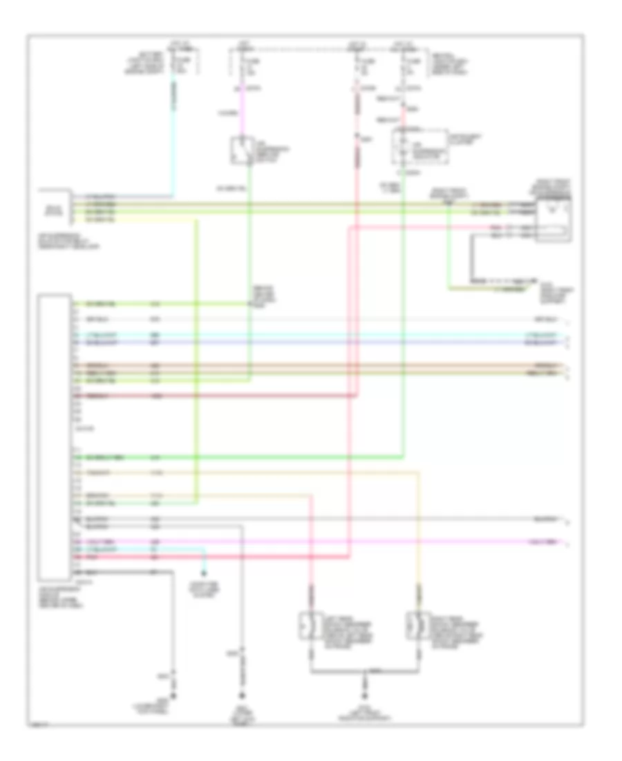
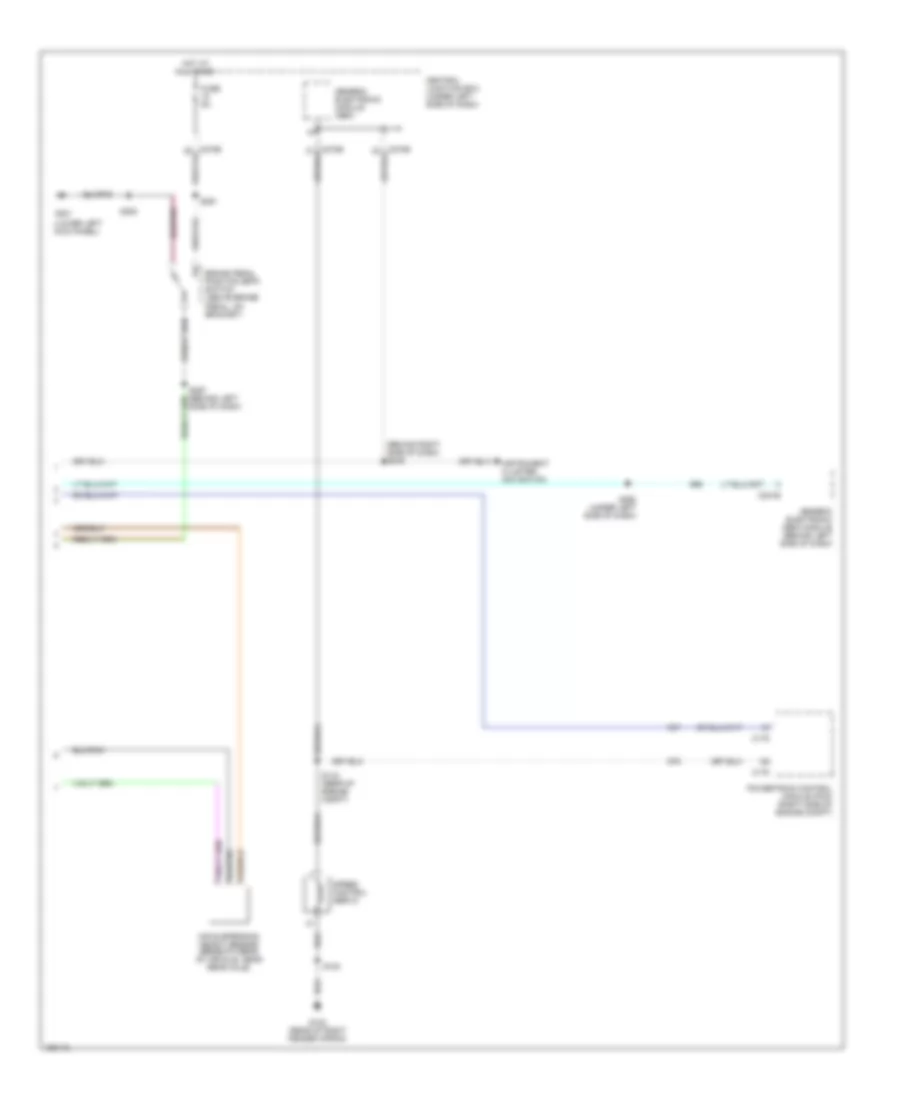
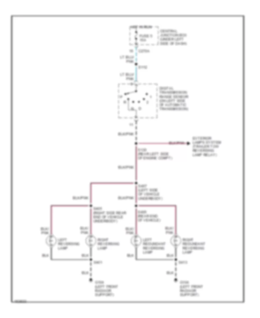
Back-up Lamps Wiring Diagram for Lincoln Blackwood 2003
List of elements for Back-up Lamps Wiring Diagram for Lincoln Blackwood 2003:
- C270a
- Central junction box (under left side of dash)
- Digital transmission range sensor (on left side of automatic transmission)
- Exterior lamps system (trailer tow reversing lamp relay)
- Fuse 5 15a
- G104 (left front radiaor support)
- Hot in run
- Left redundant reversing lamp
- Left reversing lamp
- Right redundant reversing lamp
- Right reversing lamp
- S112
- S130 (rear left side of engine compt)
- S401
- S405 (rear end of vehicle)
- S405 (right side rear end of vehicle underbody)
- S407 (left side of vehicle underbody)
- S413
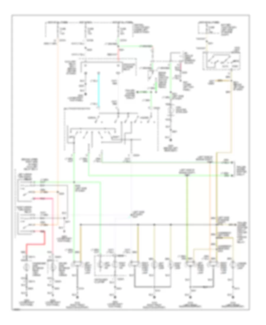
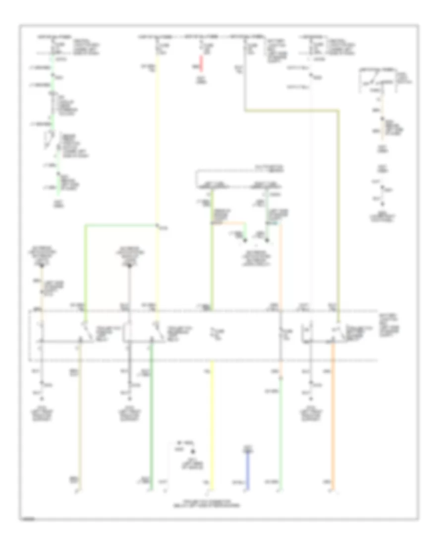
Exterior Lamps Wiring Diagram for Lincoln Blackwood 2003
List of elements for Exterior Lamps Wiring Diagram for Lincoln Blackwood 2003:
- (behind upper right side of dash) auxiliary relay box 3
- (left side of dash) s247
- (left side of engine compt) s149
- (left side of engne compt) s173
- (not used)
- (underbody left side) s406
- (underbody rear end) s403
- 87a
- Auto
- Auxiliary relay box 1 (behind center of dash)
- Battery junction box (left side of engine compt)
- Brake pedal position switch (above brake pedal)
- C202a
- C220a
- C220b
- C270a
- C270b
- C520a
- C601a
- Central junction box (under left side of dash)
- Driver side exterior rear view mirror
- Fuse 10a
- Fuse 15a
- Fuse 20a
- Fuse 7.5a
- G103 (right front radiator support)
- G104 (left front radiator support)
- G200 (lower right kick panel)
- G201 (lower left kick panel)
- G300 (behind left rear seat)
- Hazard
- Head
- High mounted stoplamp
- Hot at all times
- Hot in run
- Indicator flasher relay
- Instrument cluster
- Left
- Left front park/ turn lamp
- Left mirror turn signal relay
- Left rear park/ turn lamp
- Left side lamp
- Left turn ind
- License plate lamp
- Main light switch
- Multifunction switch
- Nca
- Normal
- Of engine compt) s115
- Off
- Park
- Passenger side exterior rear view mirror
- Pnk
- Red
- Rfi module (near steering column)
- Right
- Right front park/ turn lamp
- Right mirror turn signal relay
- Right rear park/ turn lamp
- Right side lamp
- Right turn ind
- S104
- S202
- S204
- S208
- S220
- S221
- S224 (behind left side of dash)
- S228
- S231 (left side of dash)
- S241
- S246 (left side of dash)
- S271
- S401
- S413
- S500
- S600
- S907
- Trailer/ camper adapter circuit
- Trailer/ camper adapter circuit (trailer tow parking lamp relay)
Trailer/Camper Adapter Wiring Diagram for Lincoln Blackwood 2003
List of elements for Trailer/Camper Adapter Wiring Diagram for Lincoln Blackwood 2003:
- (exterior lights system (exterior lamps circuit)
- (left side of engine compt) s149
- (not used)
- (rear of engine compt) s137
- Battery junction box (left side of engine compt)
- Brake pedal position switch (under left side of dash)
- C202a
- C270a
- C270b
- Central junction box (under left side of dash)
- Exterior lights system (back-up lamps circuit)
- Exterior lights system (exterior lights circuit)
- Fuse 10a
- Fuse 20a
- Fuse 30a
- G104 (left front radiator support)
- G200 (lower right kick panel)
- G411 (left rear of vehicle)
- Head
- Hot at all times
- Hot in run
- Left turn signal output
- Main light switch
- Multifunction switch
- Off
- Park
- Red
- Rfi module (near steering column)
- Right turn signal output
- S105
- S108
- S201
- S221
- S224 (behind left side of dash)
- S228
- S231 (behind left side of dash)
- S425
- Trailer tow battery charge relay
- Trailer tow connector (below left side of rear bumper)
- Trailer tow parking lamp relay
- Trailer tow reversing lamp relay
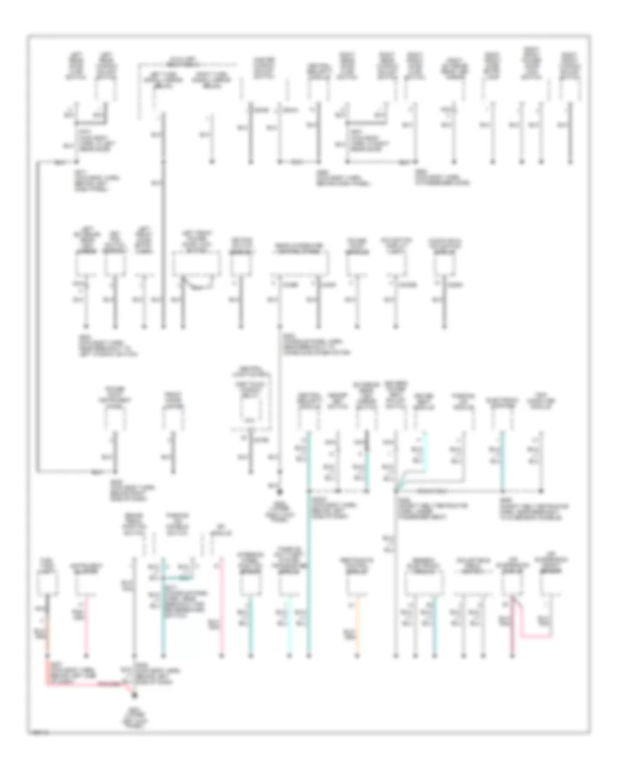
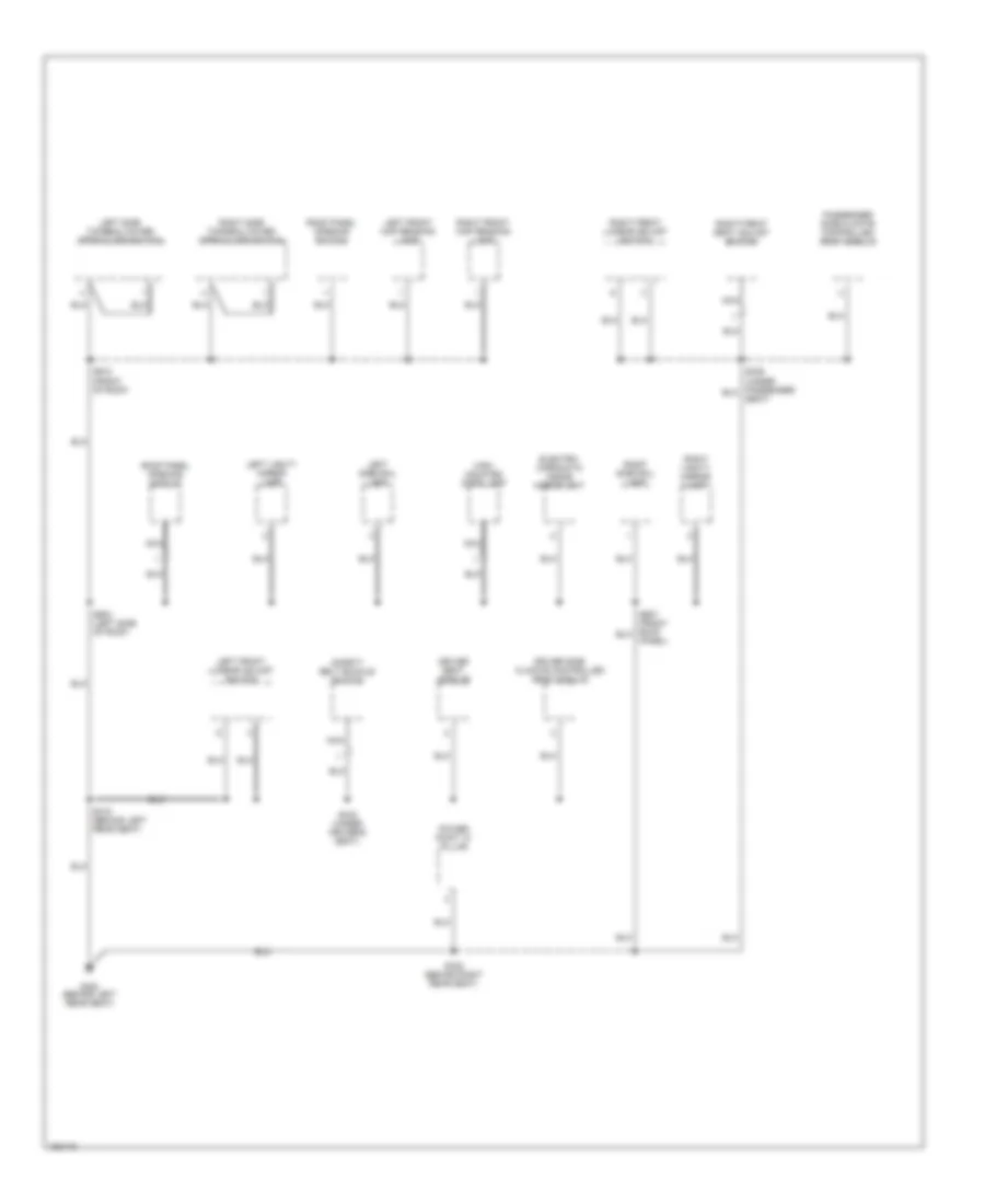
GROUND DISTRIBUTION
Ground Distribution Wiring Diagram (1 of 4) for Lincoln Blackwood 2003
List of elements for Ground Distribution Wiring Diagram (1 of 4) for Lincoln Blackwood 2003:
- (not used)
- A/c clutch field coil
- A/c compressor clutch diode
- Adjustable pedal switch
- Air suspension module
- Ashtray illum- ination lamp
- Autolamp sensor
- Auxiliary relay box 1
- Battery
- Battery junction box
- Brake shift interlock
- C205a
- C205b
- Cd changer
- Clock
- Crankshaft position sensor shield
- Data link connector
- Electronic automatic temperature control module
- Engine compartment lamp
- Front blower motor speed controller
- G101 (center of firewall)
- G102 (rear of right fender apron)
- G105 (left side of engine compartment)
- G106 (left side of engine compartment)
- G107 (right side of engine compartment)
- G200 (lower right kick panel)
- G202 (upper left kick panel)
- Glove box lamp
- Harn, in center console)
- Indicator flasher relay
- Instrument cluster
- Left cylinder head)
- Main light switch
- Mass airflow sensor
- Nca
- Powertrain control module
- Radio
- Rear integrated control panel
- Rear window defrost switch
- S102 (engine control sensor harn, near breakout to starter motor relay)
- S176 (fuel charge harn, nca
- S201 (main body harn, behind center of dash)
- S202 (main body harn, near breakout to auxiliary relay box 1)
- S203 (main body harn, behind right side of dash)
- S204 (main body harn, near breakout to instrument cluster)
- Speed control servo
- Subwoofer amplifier
- Traction control switch
- W/ eatc
- Windshield wiper motor
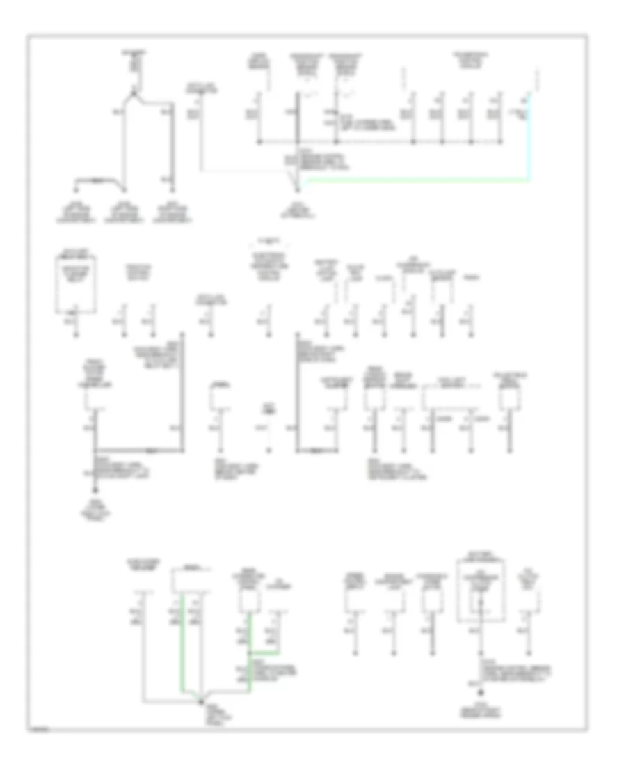
Ground Distribution Wiring Diagram (2 of 4) for Lincoln Blackwood 2003
List of elements for Ground Distribution Wiring Diagram (2 of 4) for Lincoln Blackwood 2003:
- Air suspension compressor
- Air suspension solid state relay
- Anti-lock brake system control module
- Battery junction box
- Brake fluid level switch
- C4049
- C4050
- C4051
- C4052
- C4054a
- C4054d
- Cargo door ajar switch
- Cargo door ajar switch 2
- Fog lamp relay
- Fuel tank unit
- G103 (right front radiator support)
- G104 (left front radiator support)
- G401 (left rear end of vehicle)
- Harn, near breakout for abs module)
- Horn
- Left cargo area strip lamp
- Left fog lamp
- Left front park/ turn lamp
- Left front side lamp
- Left headlamp
- Left rear park/ turn lamp
- Left rear shock absorber solenoid valve
- Left redundant reversing lamp
- Left reversing lamp
- Left tonneau cover latch actuator
- License plate lamp
- Nca
- Of engine compt)
- Of vehicle)
- Pcm power relay
- Rear power point
- Right cargo area strip lamp
- Right fog lamp
- Right front park/ turn lamp
- Right front side lamp
- Right headlamp
- Right rear park/ turn lamp
- Right rear shock absorber solenoid valve
- Right redundant reversing lamp
- Right reversing lamp
- Right tonneau cover latch actuator
- S103 (engine control harn, right front of engine compt)
- S104 (engine control harn, right front of engine compt)
- S106 (engine control harn, in breakout to g104)
- S400 (rear lamp harn, left side of vehicle underbody)
- S401 (rear lamp harn, rear of vehicle underbody)
- S418 (behind left side of loading space lining)
- S419 (behind right side of loading space lining)
- S425
- Tonneau cover control module
- Tonneau cover lamp
- Trailer tow battery charge relay
- Trailer tow connector
- Trailer tow parking lamp relay
- Trailer tow reversing lamp relay
- Washer fluid level switch
- Windshield washer pump motor
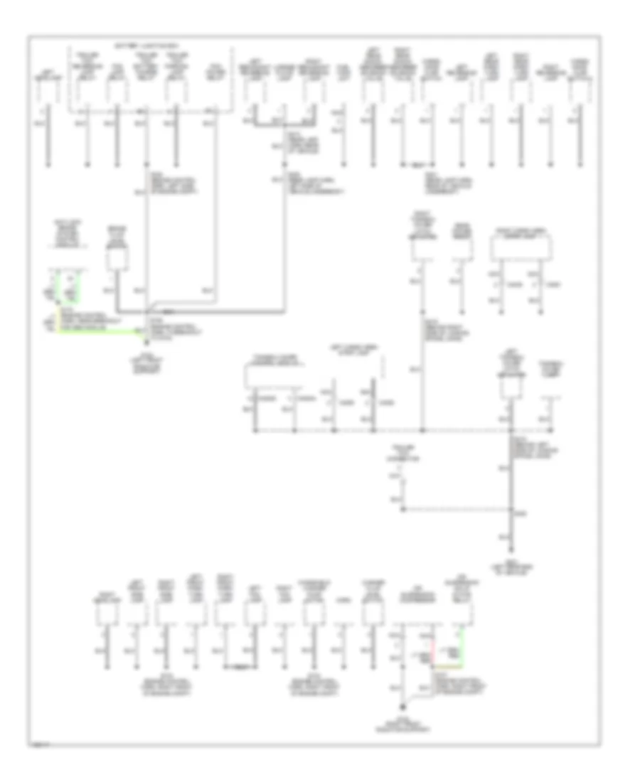
Ground Distribution Wiring Diagram (3 of 4) for Lincoln Blackwood 2003
List of elements for Ground Distribution Wiring Diagram (3 of 4) for Lincoln Blackwood 2003:
- 87a
- Adjustable pedal switch
- Air suspension height sensor
- Air suspension module
- Audiovisual navigation module
- Auxiliary relay box 3
- Brake pedal position switch
- C229a
- C270b
- C3030b
- C349a
- C349b
- C504a
- C504b
- Central junction box
- Central security module
- Driver seat module
- Driver's power seat adjust switch
- Electronic compass
- Exterior rear view mirror switch
- Front gigar lighter
- Fuel tank unit
- G200 (lower right kick panel)
- G201 (lower left kick panel)
- Generic electronic module
- Instrument cluster
- Key pad switch assembly
- Keypad switch assembly
- Left exterior rear view mirror
- Left front door entry lamp
- Left front power door lock switch
- Left rear door ajar switch
- Left rear window adjust switch
- Left turn signal mirror relay
- Master window adjust switch
- Memory set switch
- Navigation display unit
- Nca
- One touch window relay
- Parking aid disable switch
- Parking aid module
- Passive anti-theft system transceiver module
- Power point console
- Power point instrument panel
- Rear door)
- Rear integrated control panel
- Restraints control module
- Rfi module
- Right exterior rear view mirror
- Right front door ajar switch
- Right front door entry lamp
- Right front power door lock switch
- Right front window adjust switch
- Right rear door ajar switch
- Right rear window adjust switch
- Right turn signal mirror relay
- S2000 (main body harn, behind left side of dash)
- S205 (main body harn, behind right side of dash)
- S207 (main body harn, behind left side of dash)
- S260 (main body harn, behind dash panel)
- S271 (main body harn, behind left dash panel)
- S308 (safety belt retractor harn, under passenger seat)
- S323 (console panel harn, near breakout to console blower motor)
- S500 (main body harn, near breakout to left window switch)
- S600 (main body harn, in passenger door)
- S701 (main body harn, in left rear door)
- S909 (safety belt retractor harn, near breakout to overhead console)
- Steering wheel position sensor
- Trip computer module
Ground Distribution Wiring Diagram (4 of 4) for Lincoln Blackwood 2003
List of elements for Ground Distribution Wiring Diagram (4 of 4) for Lincoln Blackwood 2003:
- Driver seat module
- Driver side climate controlled seat module
- Electro- chromatic inside mirror unit
- G300 (behind left rear seat)
- High mounted stop lamp
- Left front lumbar adjust switch
- Left front map reading lamp
- Left side rail lamp
- Left side tonneau cover open/close switch
- Left vanity mirror lamp
- Nca
- Panel)
- Passenger side climate controlled seat module
- Power point "c" pillar
- Right front lumbar adjust switch
- Right front map reading lamp
- Right front seat adjust switch
- Right side rail lamp
- Right side tonneau cover open/close switch
- Right vanity mirror lamp
- Roof panel opening module
- Roof panel opening switch
- S318 (behind left rear seat)
- S322 (behind right rear seat)
- S333 (under driver's seat)
- S904 (left side of roof)
- S912 (front of roof)
- Safety belt buckle switch
- Seat)
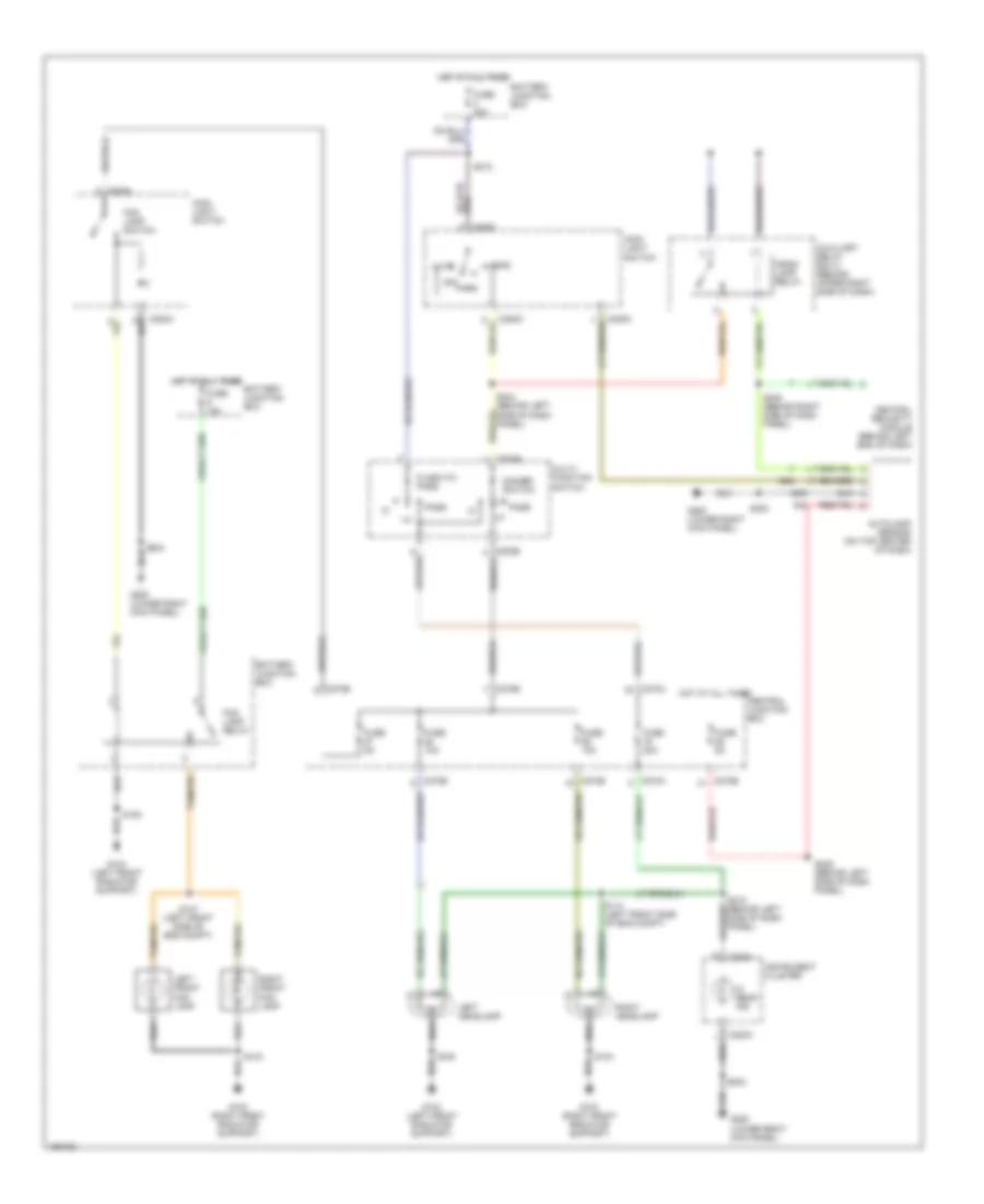
HEADLIGHTS
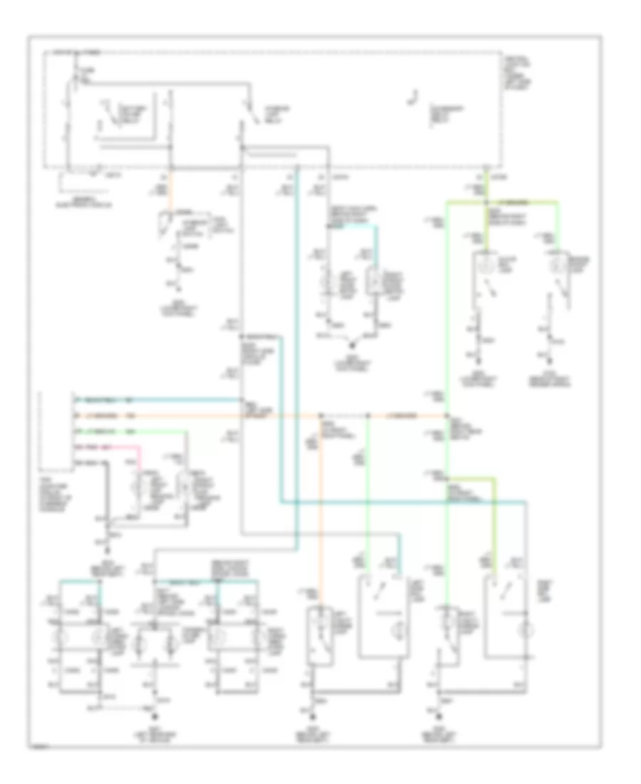
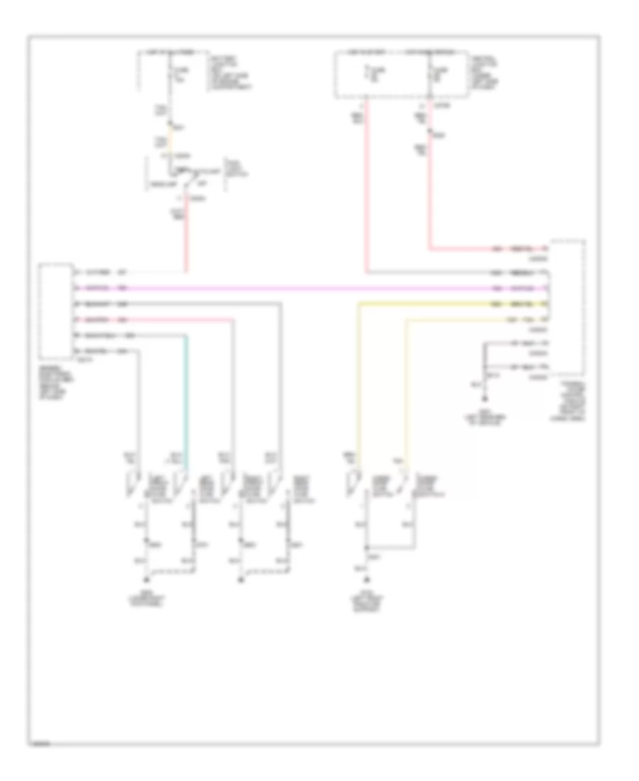
Headlights Wiring Diagram for Lincoln Blackwood 2003
List of elements for Headlights Wiring Diagram for Lincoln Blackwood 2003:
- Auto
- Autolamp sensor (on top center of dash)
- Auxiliary relay box 2 (behind upper right side of dash)
- Battery junction box
- C202b
- C205a
- C220a
- C270a
- C270b
- Central junction box
- Central security module (behind left end of dash)
- Dimmer switch
- Flash-to- pass
- Fog lamp relay
- Fog lamp switch
- Fuse 10a
- Fuse 15a
- Fuse 20a
- Fuse 30a
- Fuse 5a
- G103 (right front radiator support)
- G104 (left front radiator support)
- G200 (lower right kick panel)
- Head
- Head- lamp relay
- Hi beam ind
- Hot at all times
- Instrument cluster
- Left front fog lamp
- Left headlamp
- Main light switch
- Multi- function switch
- Off
- Park
- Pass
- Right front fog lamp
- Right headlamp
- S103
- S104
- S105
- S114 (left front side of eng compt)
- S147 (left front side of eng compt)
- S203
- S204
- S212
- S218 (behind left side of dash panel)
- S225 (behind left side of dash panel)
- S244 (behind left side of dash panel)
- S245 (behind right side of dash panel)
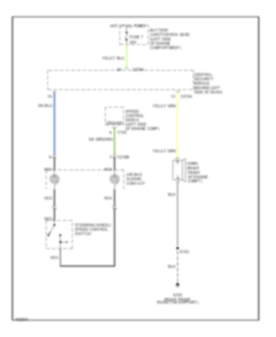
HORN
Horn Wiring Diagram for Lincoln Blackwood 2003
List of elements for Horn Wiring Diagram for Lincoln Blackwood 2003:
- 20a
- Air bag sliding contact
- Battery junction box (bjb) (left side of engine compartment)
- C122
- C218b
- C274a
- Central security module (behind left side of dash)
- Fuse 7
- G103 (right front radiator support)
- Ground
- Horn (right front of engine compt)
- Hot at all times
- Nca
- S103
- Speed control servo (left side of engine comp)
- Steering wheel/ speed control switch
INSTRUMENT CLUSTER
Instrument Cluster Wiring Diagram for Lincoln Blackwood 2003
List of elements for Instrument Cluster Wiring Diagram for Lincoln Blackwood 2003:
- (conn a)
- (conn b)
- (lower right kick panel)
- (lower right kick panel) g200
- 820 ohms
- A10
- A14
- A15
- A17
- A22
- Abs control module (on left side of engine compt)
- Air suspension module (behind upper center of dash)
- Airbag ind
- Anti-lock brakes system
- Anti-lock ind
- B10
- B11
- B12
- B13
- B16
- B17
- B18
- B19
- B20
- Bias ckt
- Brake fluid level indicator switch (on brake fluid reservoir)
- Brake ind
- C201a
- C2131a
- C220a
- C220b
- C270a
- C270b
- Central junction box
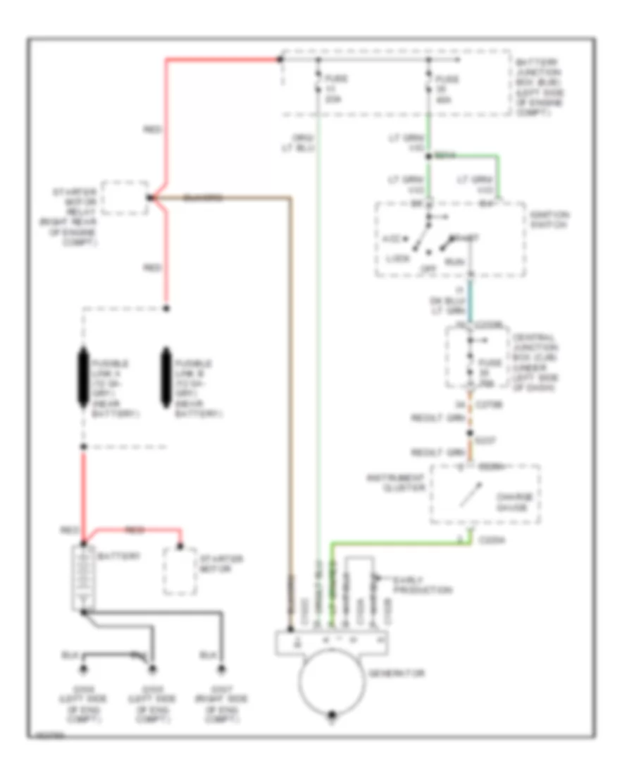
- Charge ind
- Check suspension ind
- Clock
- Computer data lines system
- Door ajar ind
- Engine compt)
- Exterior lights system
- Fasten safety belt ind
- Fuel pump unit (in fuel tank)
- Fuse 30a
- Fuse 5a
- G104 (left front radiator support)
- G200
- G201 (lower left kick panel)
- Generic electronic module (behind left side of dash)
- Headlights system
- Hi beam ind
- Hot at all times
- Hot in accy or run
- Hot in park or head
- Hot in run
- Hot in start or run
- Illumination
- Instrument cluster
- Interior lights system
- Left turn ind
- Low fuel ind
- Low oil/high coolant ind
- Low washer fluid ind
- Malfunction indicator
- Micro- processor
- Microprocessor
- Nca
- Oil pressure switch (on left front of engine, next to p/s pump)
- Parking brake switch (on right side of park brake lever)
- Passive anti-theft system transceiver module (on steering column)
- Restraints control module (behind right center of dash)
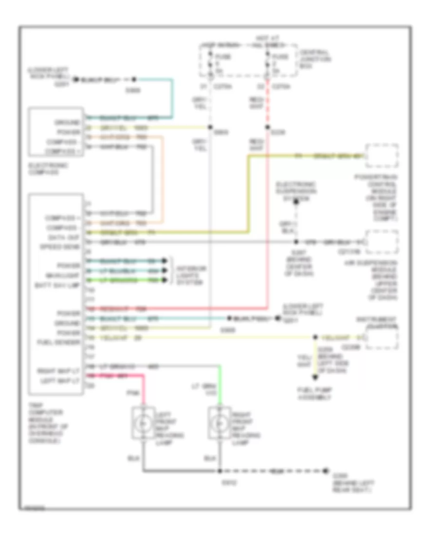
- Right turn ind
- S106
- S203
- S204
- S207
- S236
- S237
- S257
- S259 (behind left side of dash)
- S265
- S275
- Shift interlock system
- Starting/charging system
- Theft indicator micro cluster
- Traction control
- Trip computer module (in front of overhead console)
Overhead Console Wiring Diagram for Lincoln Blackwood 2003
List of elements for Overhead Console Wiring Diagram for Lincoln Blackwood 2003:
- (lower left kick panel) g201
- Air suspension module (behind upper center of dash)
- Batt sav lmp
- C2131b
- C220b
- C270a
- Central junction box
- Compass +
- Compass -
- Data out
- Electronic compass
- Electronic suspension system
- Fuel pump assembly
- Fuel sender
- Fuse 5a
- G300 (behind left rear seat)
- Ground
- Hot at all times
- Hot in run
- Instrument cluster
- Interior lights system
- Left front map reading lamp
- Left map lt
- Left side of dash)
- Main light
- Pnk
- Power
- Powertrain control module (on right side of engine compt)
- Right front map reading lamp
- Right map lt
- S236
- S267 (behind center of dash)
- S906
- S909
- S912
- Speed sens
- Trip computer module (in front of overhead console)
INTERIOR LIGHTS
Courtesy Lamps Wiring Diagram (1 of 2) for Lincoln Blackwood 2003
List of elements for Courtesy Lamps Wiring Diagram (1 of 2) for Lincoln Blackwood 2003:
- (behind right side loading space lining) s420
- (body main harn, behind right side of dash) s239
- Accessory delay relay
- Battery saver relay
- C201c
- C205b
- C270a
- C270b
- C4049
- C4050
- C4051
- C4052
- C903a
- C903b
- C908a
- C908b
- Central junction box (under left side of dash)
- Engine compt lamp
- Fuse 15a
- G102 (rear of right fender apron)
- G200 (lower right kick panel)
- G300 (behind left rear seat)
- G401 (left rear end of vehicle)
- Generic electronic module
- Glove box lamp
- Hot at all times
- Interior lamp relay
- Interior lamp switch
- Left cargo area strip lamp
- Left front door entry lamp
- Left front map reading lamp
- Left side rail lamp
- Left vanity mirror lamp
- Main light switch
- Nca
- Pnk
- Pnk
- Right front door entry lamp
- Right front map reading lamp
- Right cargo area strip lamp
- Right side rail lamp
- Right vanity mirror lamp
- S102
- S203
- S204
- S240 (behind right side of dash)
- S309 (right side vehicle floor)
- S321 (behind right rear seats)
- S418
- S419
- S500
- S600
- S900 (left side of roof)
- S904
- S907
- S908 (in front roof panel)
- S912
- Tonneau cover lamp
- Trip computer module (in front of overhead console)
Courtesy Lamps Wiring Diagram (2 of 2) for Lincoln Blackwood 2003
List of elements for Courtesy Lamps Wiring Diagram (2 of 2) for Lincoln Blackwood 2003:
- Autolamp
- Battery junction box (on left side of engine compartment)
- C201a
- C205a
- C270b
- C4054a
- C4054c
- C4054d
- Cargo door ajar switch
- Cargo door ajar switch 2
- Central junction box (under left side of dash)
- Fuse 15a
- Fuse 5a
- G104 (left front radiator support)
- G200 (lower right kick panel)
- G401 (left rear end of vehicle)
- Generic electronic module (gem) (behind left side of dash)
- Headlamp
- Hot at all times
- Hot in acc or run
- Hot in start
- Left front door ajar switch
- Left rear door ajar switch
- Main light switch
- Off
- Park
- Right front door ajar switch
- Right rear door ajar switch
- S225
- S241
- S401
- S418
- S500
- S600
- S701
- S801
- Tan
- Tonneau cover control module (on right front of cargo area)
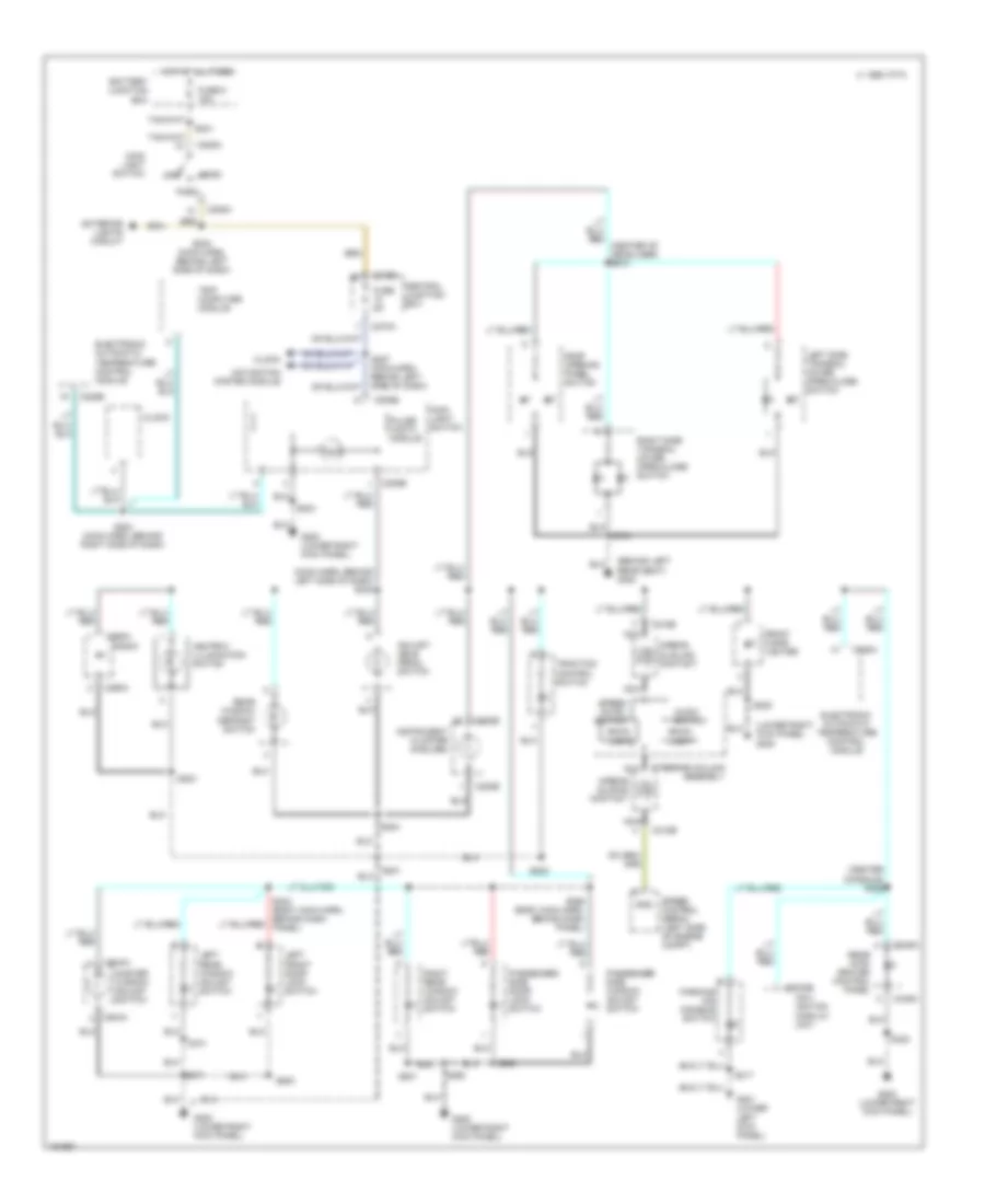
Instrument Illumination Wiring Diagram for Lincoln Blackwood 2003
List of elements for Instrument Illumination Wiring Diagram for Lincoln Blackwood 2003:
- (behind left rear seat) g300
- (center console) s326
- (lower right kick panel) g200
- (main harn, behind left side of dash) s242
- 1995 vftc c
- Adjust- able pedal switch
- Airbag slidilng contact
- Airbag sliding contact
- Ashtray illumination switch
- Audio switch
- Back- light
- Battery junction box
- C205a
- C205b
- C218b
- C220b
- C228a
- C228b
- C270a
- C270b
- C290a
- C3030b
- C349a
- C504a
- Central junction box
- Clock
- Electronic automatic temperature control module
- Exterior lights circuit
- Front cigar lighter
- Fuse 5a
- Fuse 6 15a
- G200 (lower right kick panel)
- G201 (lower left kick panel)
- Gnd
- Head
- Hot at all times
- Instrument cluster (6 bulbs)
- Left front door lock switch
- Left rear window adjust switch
- Left side tonneau cover open/close switch
- Main light switch
- Master window adjust switch
- Nav- igation display unit
- Navigation system module
- Nca
- Off
- Park
- Parking aid disable switch
- Passenger side door lock switch
- Passenger side window adjust switch
- Pulse width module
- Radio
- Rear inte- grated control panel
- Rear window defrost switch
- Right rear window adjust switch
- Right side tonneau cover open/close switch
- Roof opening panel switch
- S201
- S202
- S203
- S204
- S205
- S224 (main harn, behind left side of dash)
- S241
- S256 (body main harn, behind dash panel)
- S257 (main harn, behind left side of dash)
- S260
- S271
- S284 (main harn, behind right side of dash)
- S317
- S323
- S500
- S600
- S701
- S801
- S912
- Speed cntrl switch
- Speed control servo (left side of engine compt)
- Steering column assembly
- Traction control switch
- Trip computer module
MEMORY SYSTEMS
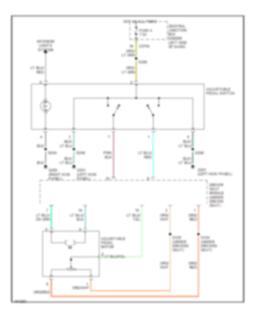
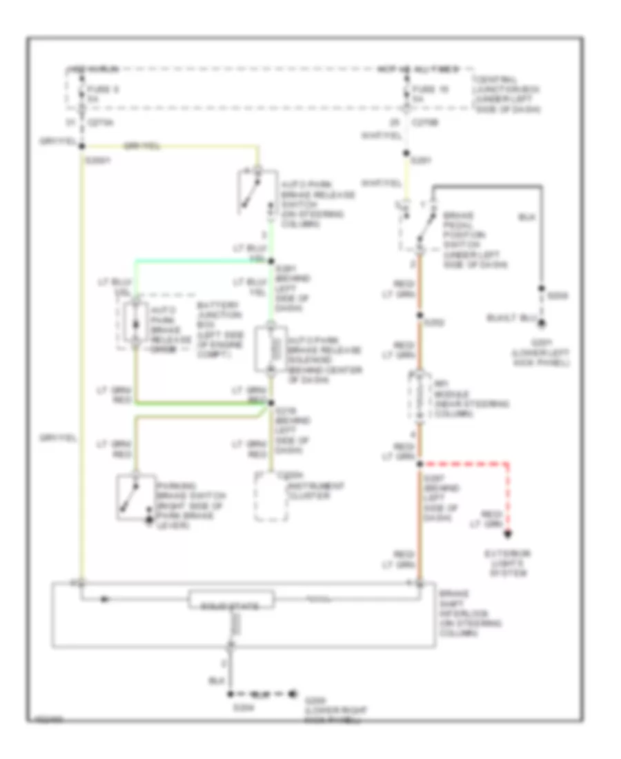
Adjustable Pedal Wiring Diagram for Lincoln Blackwood 2003
List of elements for Adjustable Pedal Wiring Diagram for Lincoln Blackwood 2003:
- Adjustable pedal motor
- Adjustable pedal switch
- C270a
- Central junction box (under left side of dash)
- Driver seat module (under driver seat)
- Fuse 4 7.5a
- G200 (right kick panel)
- G201 (left kick panel)
- Hot at all times
- Interior lights system
- S204
- S208
- S290
- S334 (under drivers seat)
- S335 (under drivers seat)
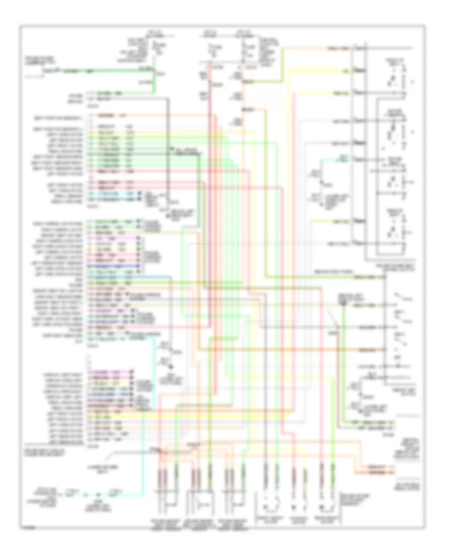
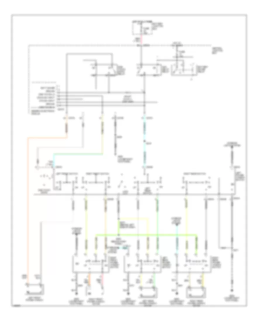
Driver"s Memory Seat Wiring Diagram for Lincoln Blackwood 2003
List of elements for Driver"s Memory Seat Wiring Diagram for Lincoln Blackwood 2003:
- (behind dash panel)
- (behind left side of dash)
- (lower left inner kick panel) g201
- (lower left kick panel) g201
- (under drivers seat)
- (under left side of dash)
- Adj. brake pedal circuit
- Adjustable pedal motor
- Battery junction box (on left side of engine compartment)
- Behind left rear seat) g300
- C270a
- C270b
- C274b
- C341a
- C341b
- C341c
- C341d
- Central junction box (under left side of dash)
- Central security module (behind left side of dash)
- Data link connector (dlc) (under center of dash)
- Dlc
- Driver memory seat front height sensor
- Driver memory seat horizontal sensor
- Driver memory seat rear height sensor
- Driver power lumber switch
- Driver power motor seat assembly
- Driver power seat control switch
- Driver seat module (under driver seat)
- Entire seat
- Front height motor
- Front of seat
- Fuse 30a
- Fuse 5a
- Fuse 7.5a
- Fwd
- Fwd/rwd motor
- G201 (lower left kick panel)
- Gnd
- Ground
- Hot at all times
- Hot in start
- Lefft horiz motor
- Left front motor
- Left horiz motor
- Left mirr up/dn mtr gnd
- Left mirr up/dn pos sens
- Left mirror l/r mtr
- Left mirror l/r mtr gnd
- Left mirror posit sensor
- Left rear motor
- Mem 1
- Mem 2
- Memory seat sw lamp dr
- Memory seat sw posit 1
- Memory seat sw posit 2
- Memory seat sw set
- Memory set switch
- Mirr posit sens gnd
- Mirr posit sensor feed
- Mirr sw horiz left
- Mirr sw horiz right
- Mirr sw vert left
- Mirr sw vert right
- Mirror sw common
- Nca
- Pedal backward
- Pedal forward
- Pedal sensor
- Power
- Power mirrors system
- Rear height motor
- Rear of seat
- Red
- Right mirr l/r posit sens
- Right mirr up/dn mtr gnd
- Right mirr up/dn posit
- Right mirror l/r mtr
- Right mirror l/r mtr gnd
- Right mirror up/dn mtr
- Rwd
- S2000
- S2009
- S219
- S220
- S292
- S295
- S296
- S308
- S332
- S333
- S334
- S335
- Seat posit sensor front
- Seat posit sensor horiz
- Seat posit sensor rear
- Seat position sensor (+)
- Seat position sensor (-)
- Set
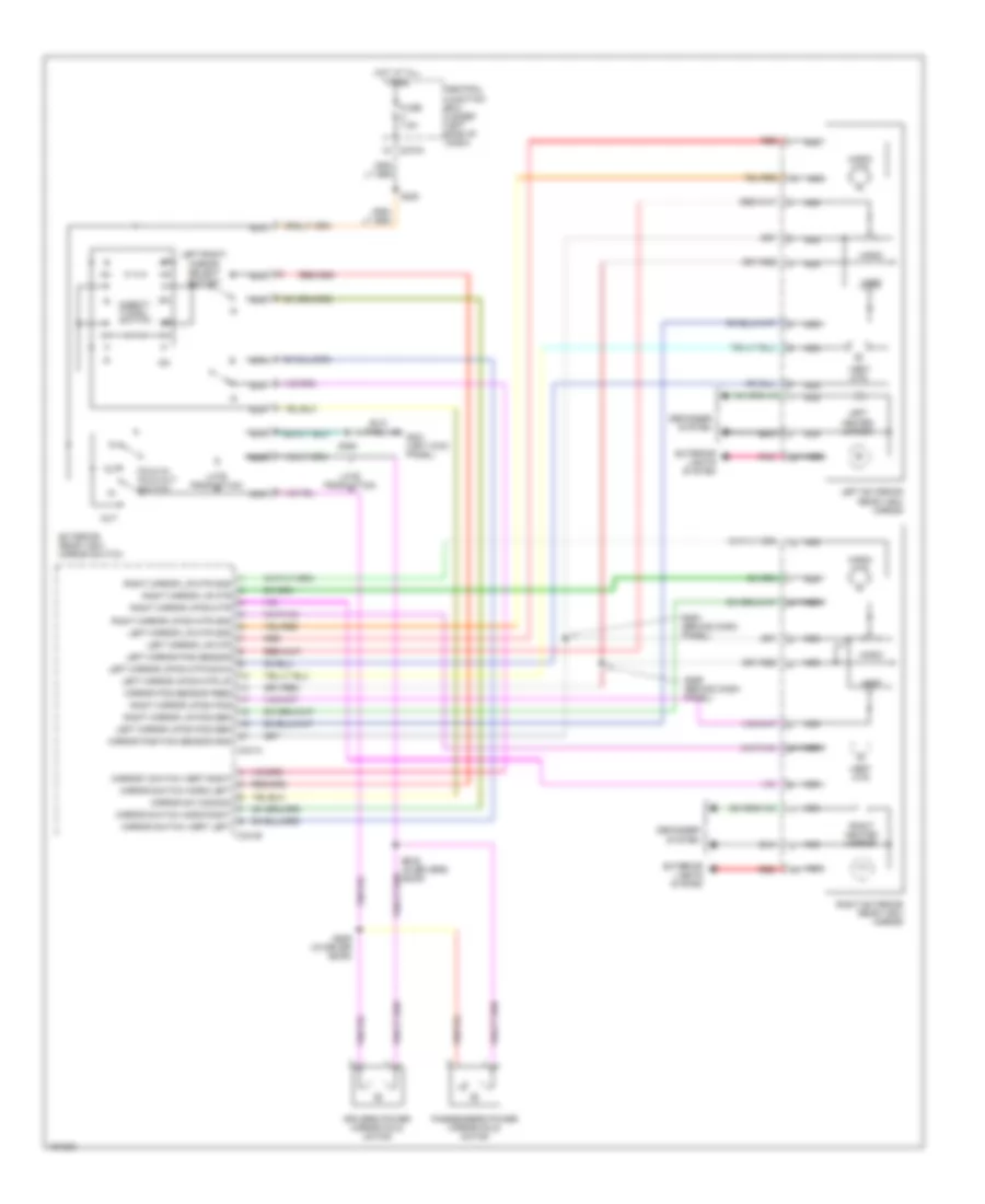
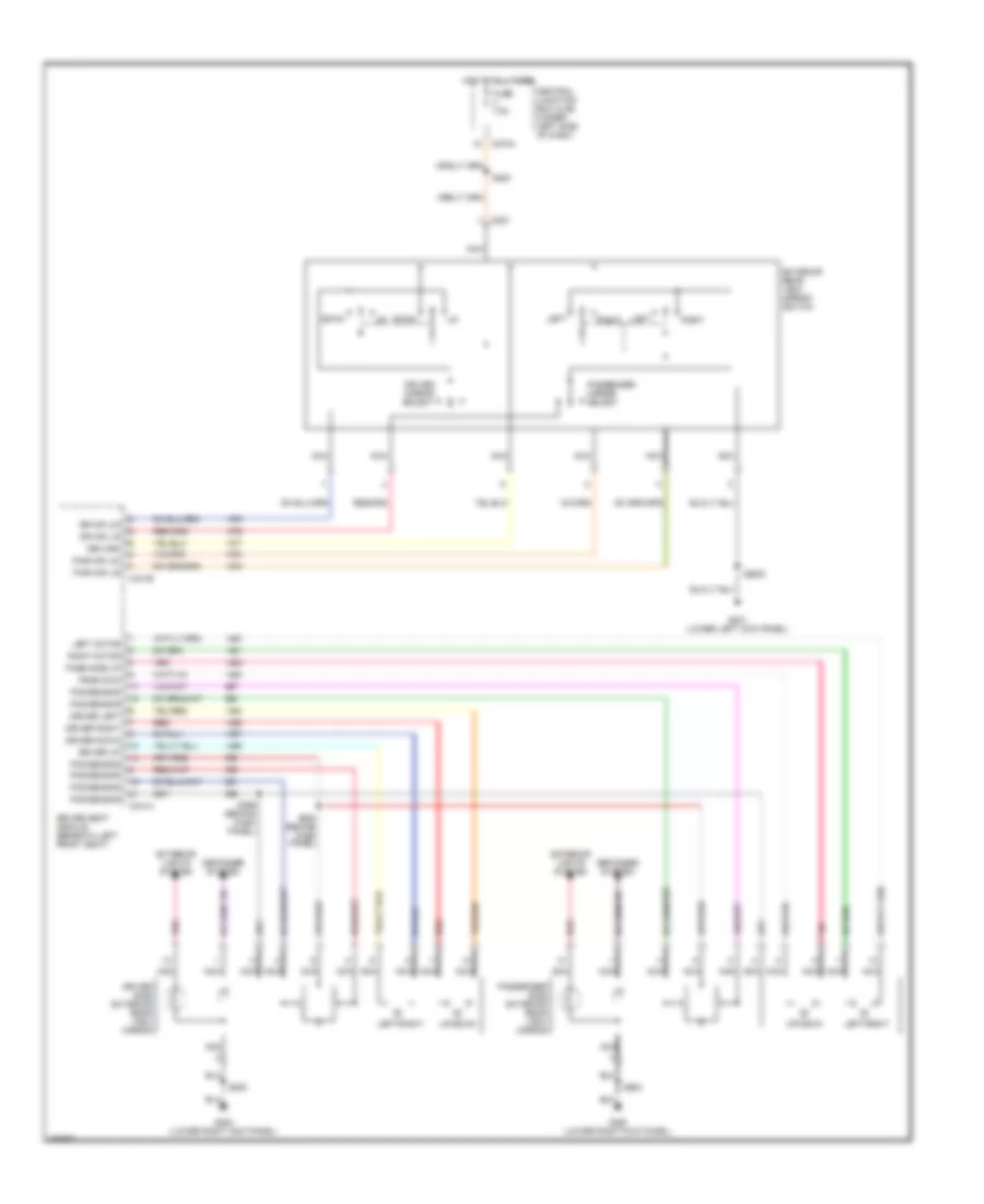
Memory Mirrors Wiring Diagram for Lincoln Blackwood 2003
List of elements for Memory Mirrors Wiring Diagram for Lincoln Blackwood 2003:
- C270a
- C341a
- C341b
- Central junction box (under left side of dash)
- Defogger system
- Direct- tional switch
- Drivers power mirror fold motor
- Exterior rear view mirror switch
- Exterior lights system
- Fold in/ fold out switch
- Fuse 7.5a
- G201 (left kick panel)
- Horiz
- Horiz mtr
- Hot at all times
- Late production
- Left exterior rear view mirror
- Left heated mirror
- Left mirror l/r mtr
- Left mirror l/r mtr gnd
- Left mirror pos sensor
- Left mirror up/dn mtr down
- Left mirror up/dn mtr up
- Left mirror up/dn pos sen
- Left/right mirror select switch
- Mirror pos sensor feed
- Mirror position sensor gnd
- Mirror sw common
- Mirror switch horiz left
- Mirror switch horiz right
- Mirror switch vert left
- Mirrory switch vert right
- Nca
- Out
- Passengers power mirror fold motor
- Pnk
- Red
- Right exterior rear view mirror
- Right heated mirror
- Right mirror l/r mtr
- Right mirror l/r mtr gnd
- Right mirror l/r pos sen
- Right mirror up/dn mtr
- Right mirror up/dn mtr gnd
- Right mirror up/dn pos
- S220
- S250
- S294 (behind dash panel)
- S299 (behind dash panel)
- S508 (in drivers door)
- S509 (in driver door)
- Vert
- Vert mtr
NAVIGATION
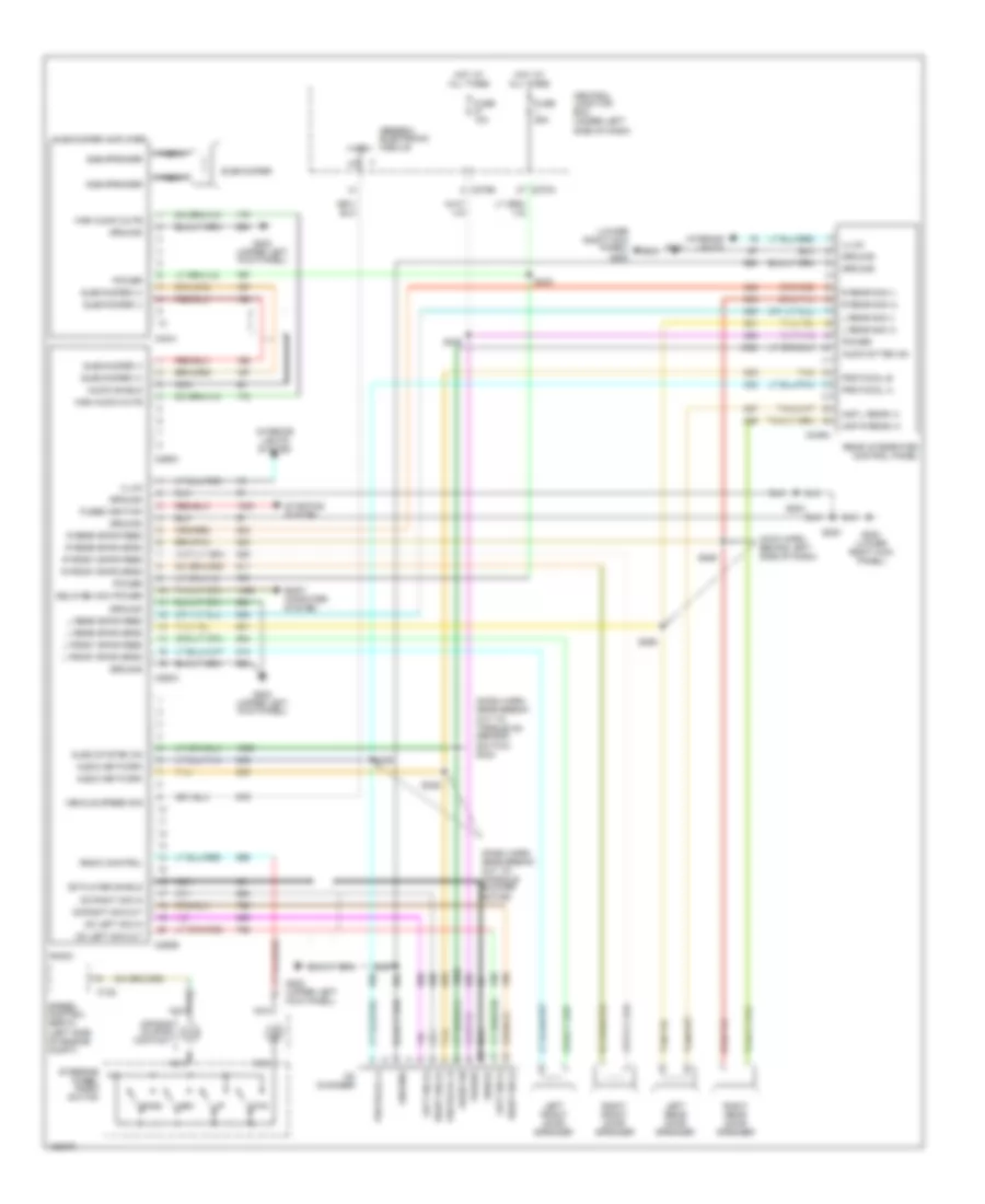
Navigation Wiring Diagram for Lincoln Blackwood 2003
List of elements for Navigation Wiring Diagram for Lincoln Blackwood 2003:
- (under center console) s323
- Audio visual navigation (avn) module (below center console)
- C201c
- C229a
- C229b
- C229c
- C229d
- C270a
- C270b
- C3030a
- C3030b
- Central junction box (under left side of dash)
- Exterior lights system
- Fuse 18 5a
- Fuse 2 5a
- Fuse 8 5a
- G200 (lower right kick panel)
- Generic electronic module (gem)
- Gps antenna
- Hot at all times
- Hot in accy or run
- Hot in park or head
- Interior lights system
- Navigation display unit
- Red
- S275 (behind left side of dash)
- S330 (under center console)
- S331 (under center console)
- Sheild
- Shield
Parking Assistant Wiring Diagram for Lincoln Blackwood 2003
List of elements for Parking Assistant Wiring Diagram for Lincoln Blackwood 2003:
- (behind left kick panel)
- (rear end of vehicle)
- Central junction box
- Data link connector (under center of dash)
- Driver seat module
- Exterior lights system (back up lights)
- Fuse 6 5a
- G201
- Ground
- Hot in run
- Instrument illumination
- Iso 9141
- Left center sensor input
- Left inner parking aid sensor
- Left outer parking aid sensor
- Left outer sensor input
- On/off switch
- Parking aid disable switch (in glove box)
- Parking aid module (below right rear seat)
- Parking aid speaker
- Power
- Reverse input
- Right center sensor input
- Right inner parking aid sensor
- Right outer parking aid sensor
- Right outer sensor input
- S229 (behind left side of dash)
- S292 (under left side of dash)
- S308
- S317
- S415
- S416
- S906
- Sensor ground
- Sensor power
- Speaker (+)
- Speaker (-)
- Status led
- To multiplex communication network
- W/memory seat
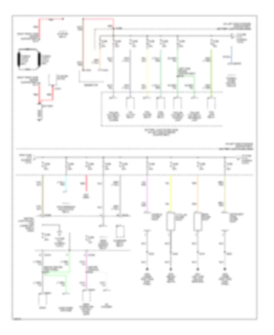
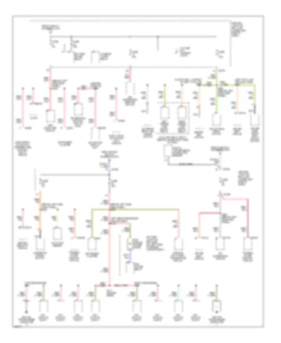
POWER DISTRIBUTION
Power Distribution Wiring Diagram (1 of 5) for Lincoln Blackwood 2003
List of elements for Power Distribution Wiring Diagram (1 of 5) for Lincoln Blackwood 2003:
- "c" pillar power point
- (behind center dash panel) s233
- (center console) s328
- (left side engine compartment) s108
- (not used)
- (on left side of engine compartment) battery junction box (bjb)
- (right front side engine compartment) s177
- (right front side engine compartment) s178
- A/c clutch relay
- Accessory delay relay
- Air suspension solid state relay
- Battery
- Battery junction box (bjb) (on left side of engine compartment)
- C102a
- C102c
- C1093
- C197a
- C270a
- C270b
- C290a
- C349a
- C4054d
- Cd changer
- Central junction box (cjb) (under left side of dash)
- Console power point
- Fog lamp relay
- From fuse f1.9 a (diagram 1 of 5)
- Fuel pump relay
- Fuse 10a
- Fuse 15a
- Fuse 20a
- Fuse 25a
- Fuse 30a
- Fuse 40a
- Fuse 50a
- G200 (under right side dash panel)
- G300 (behind rear seats)
- G401 (left side vehicle rear end)
- Generator
- Instrument panel power point
- Nca
- Pcm power relay
- Radio
- Rear integrated control panel (ricp)
- Rear power point
- Rear window defrost relay
- Red
- S205
- S322
- S323
- S419
- Starter motor
- Starter relay
- Subwoofer amplifier
- To fuse f1.27 (diagram 1 of 5)
- To fuse f1.44 (diagram 2 of 5)
- To fuse f2.2 (diagram 3 of 5)
- Tonneau cover control module
- Trailer tow relay, battery charge
- Trailer tow relay, parking lamp
- Trailer tow relay, reversing lamp
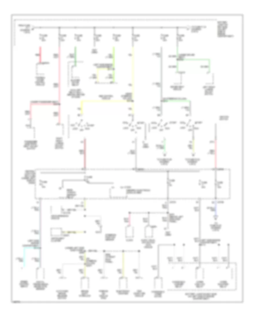
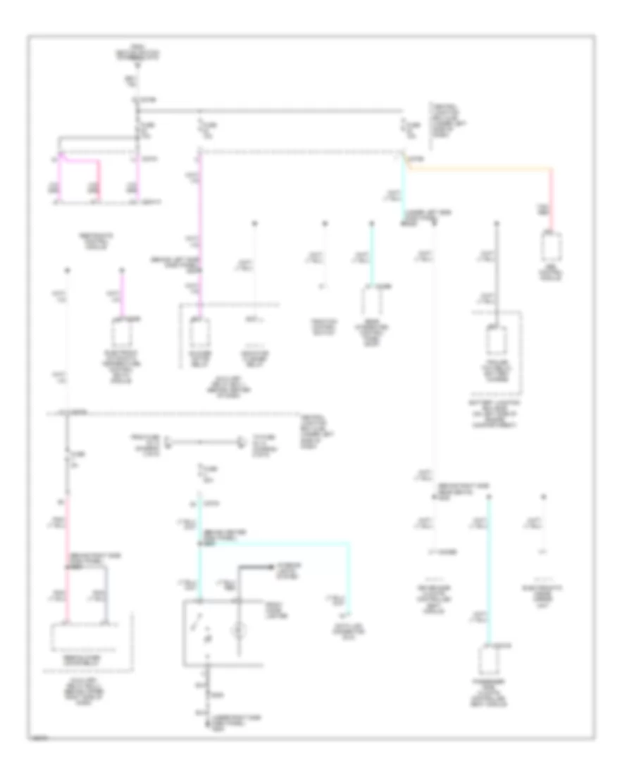
Power Distribution Wiring Diagram (2 of 5) for Lincoln Blackwood 2003
List of elements for Power Distribution Wiring Diagram (2 of 5) for Lincoln Blackwood 2003:
- (left side engine compartment) s112
- (left side engine compartment) s171
- (near steering column) s215
- (not used)
- (on steering column) s214
- (under left side dash panel) s265
- (under passenger seat) s337
- Abs control module
- Acc
- Air suspension module
- Audio visual navigation (avn) module
- Auto park brake release switch
- Auxiliary relay box 1 (behind center of dash
- Battery junction box (bjb) (on left side of engine compartment)
- Blower motor relay
- Brake shift interlock
- C102c
- C2131b
- C220a
- C229a
- C270a
- C270b
- C341d
- C4054a
- Central junction box (cjb) (under left side of dash)
- Clock
- Digital transmission range (dtr) sensor
- Driver seat module
- Electronic compass
- From fuse f1.1 b (diagram 1 of 5)
- Fuse 15a
- Fuse 30a
- Fuse 40a
- Fuse 50a
- Fuse 5a
- Generic electronic module (gem)
- Ignition switch
- Instrument cluster
- Left front lumbar adjust switch
- Lock
- Nca
- Off
- Parking aid module (pam)
- Passenger side front seat adjust switch
- Rear window defrost relay
- Red
- Right front lumbar adjust switch
- Run
- S275 (behind left side dash panel)
- S906 (in front roof panel)
- Speed control servo
- Sta
- Start
- Steering position sensor
- To fuse f1.34 (diagram 5 of 5)
- To fuse f2.20 (diagram 3 of 5)
- To fuse f2.22 (diagram 4 of 5)
- To fuse f2.29 (diagram 3 of 5)
- Tonneau cover control module
- Trip computer module
- Windshield washer relay
- Windshield wiper motor
- Wiper high/low relay
- Wiper run/park relay
Power Distribution Wiring Diagram (3 of 5) for Lincoln Blackwood 2003
List of elements for Power Distribution Wiring Diagram (3 of 5) for Lincoln Blackwood 2003:
- (behind left side dash panel) s225
- (behind left side dash panel) s236
- (center console) s330
- (in footwell, in front of left "a" pillar) s220
- (left "b" pillar vehicle floor) s307
- (right side engine) s162
- (top rear engine) s161
- Adjustable pedal switch
- Air suspension module
- Air suspension service switch
- Audio visual navigation (avn) module
- Autolamp sensor
- Auxiliary relay box 3 (behind upper right side of dash)
- Battery junction box (bjb) (on left side of engine compartment)
- Battery saver relay
- C201b
- C2131b
- C220a
- C228b
- C229a
- C270a
- C270b
- C274a
- C3030b
- C341a
- C4054c
- C4054d
- Central junction box (cjb) (under left side of dash)
- Central security module
- Clock
- Coil on plug (cop) 1
- Coil on plug (cop) 2
- Coil on plug (cop) 3
- Coil on plug (cop) 4
- Coil on plug (cop) 5
- Coil on plug (cop) 6
- Coil on plug (cop) 7
- Coil on plug (cop) 8
- Digital transmission range (dtr) sensor
- Driver seat module
- Driver side front seat adjust switch
- Electronic automatic temperature control (eatc) module
- Exterior rear view mirror switch
- From fuse f2.1 (diagram 1 of 5)
- From fuse f2.21 (diagram 2 of 5)
- From ignition switch (diagram 2 of 5)
- Fuse 15a
- Fuse 30a
- Fuse 5a
- Fuse 7.5a
- Ignition transformer capacitor
- Instrument cluster
- Interior lamps relay
- Left mirror turn signal relay
- Memory set switch
- Navigation display unit
- Nca
- Overdrive cancel switch
- Passive anti-theft transceiver module
- Pcm module power diode
- Pcm power relay
- Powertrain control module (pcm)
- Right mirror turn signal relay
- S117 (engine rear)
- S266 (behind left side dash panel)
- S290 (behind left side dash panel)
- To fuse f2.3 (diagram 4 of 5)
- Tonneau cover control module
- Trip computer module
Power Distribution Wiring Diagram (4 of 5) for Lincoln Blackwood 2003
List of elements for Power Distribution Wiring Diagram (4 of 5) for Lincoln Blackwood 2003:
- (behind center dash panel) s289
- (behind left side dash panel) s287
- (behind right side dash panel) s283
- (behind right side rear seats) s320
- (under left side dash panel) s228
- (under right side dash panel) g200
- Abs control module
- Auxiliary relay box 1 (behind center of dash)
- Auxiliary relay box 2 (behind upper right side of dash)
- Battery junction box (bjb) (on left side of engine compartmrent)
- Blower motor relay
- C2041a
- C228b
- C270a
- C270b
- C3031b
- C3036b
- C349b
- Central junction box (cjb) (under left side of dash)
- Data link connector (dlc)
- Driver side climate controlled seat module
- Electromatic inside mirror unit
- Electronic automatic temperature control (eatc) module
- From fuse f2.12 (diagram 3 of 5)
- From ignition switch (diagram 2 of 5)
- Front cigar lighter
- Fuse 10a
- Fuse 20a
- Fuse 5a
- Indicator flasher relay
- Interior lights system
- Passenger side climate controlled seat module
- Rear blower motor relay
- Rear integrated control panel (ricp)
- Restraints control module
- S205
- Tan/ red
- To fuse f2.15 (diagram 5 of 5)
- Traction control switch
- Trailer tow relay, battery charge
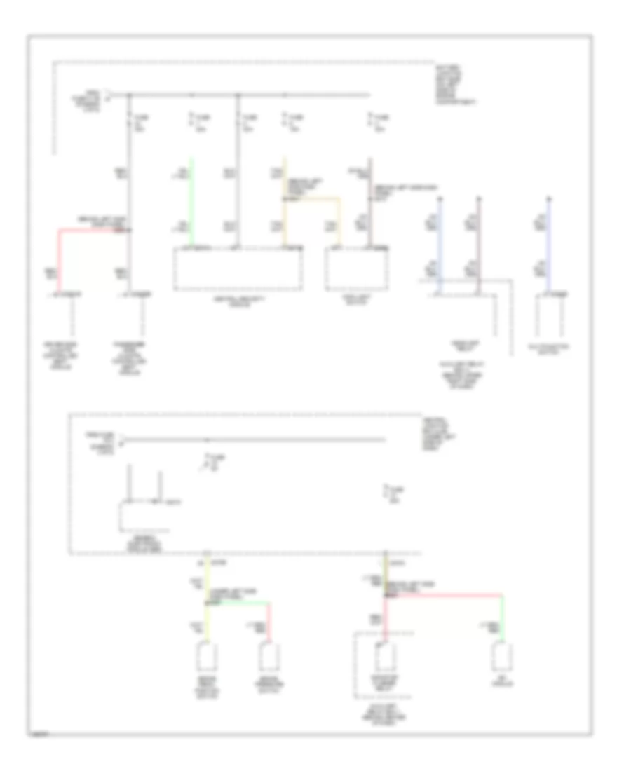
Power Distribution Wiring Diagram (5 of 5) for Lincoln Blackwood 2003
List of elements for Power Distribution Wiring Diagram (5 of 5) for Lincoln Blackwood 2003:
- (behind left side dash panel) s212
- (behind left side dash panel) s241
- (behind left side dash panel) s282
- (diagram 2 of 5)
- (under left side dash panel) s291
- Auxiliary relay box 1 (behind center of dash)
- Auxiliary relay box 2 (behind upper right side of dash)
- Battery junction box (bjb) (on left side of engine compartment)
- Brake pedal position switch
- Brake pressure switch
- C201c
- C202b
- C205a
- C270a
- C270b
- C274a
- C274b
- C3031b
- C3036b
- Central junction box (cjb) (under left side of dash)
- Central security module
- Driver side climate controlled seat module
- From fuse f1.36 m
- From fuse f2.3 (diagram 4 of 5)
- Fuse 15a
- Fuse 20a
- Fuse 30a
- Fuse 5a
- Generic electronic module (gem)
- Headlamp relay
- Indicator flasher relay
- Main light switch
- Multifunction switch
- Passenger side climate controlled seat module
- Rfi module
POWER DOOR LOCKS
Power Door Locks Wiring Diagram for Lincoln Blackwood 2003
List of elements for Power Door Locks Wiring Diagram for Lincoln Blackwood 2003:
- (behind dash panel)
- (behind left side of dash) s235
- (in front footwell, in front of left "a' pillar) s273
- All lock
- All unlock
- Battery
- Battery junction box (left side of engine compt)
- C274a
- C274b
- Central security module (under left side of dash)
- Driver side door lock actuator
- Driver side door lock switch
- Drvr lock
- Fuse 15a
- Fuse 20a
- Fuse 30a
- G200 (lower right kick panel)
- Ground
- Hot at all times
- Interior lights system
- Left rear door lock actuator
- Liftgate door lock actuator
- Lock
- Lock in
- Pass- enger side door lock switch
- Passenger side door lock actuator
- Right rear door lock actuator
- S2000
- S234 (behind left side of dash)
- S241
- S260
- S270
- S500
- S600
- Unlock
- Unlock in
POWER MIRRORS
Electronic Day/Night Mirror Wiring Diagram for Lincoln Blackwood 2003
List of elements for Electronic Day/Night Mirror Wiring Diagram for Lincoln Blackwood 2003:
- C270a
- C270b
- Central junction box (cjb) (behind left side of dash)
- Digital transmission range (dtr) sensor (lower left side of automatic transmission)
- Electrochromatic inside mirror unit
- Exterior lights system
- Fuse 10a
- Fuse 15a
- G300 (behind left rear seat)
- Hot in run
- Navigation system
- Navigation system anti-theft system
- S130 (left rear engine compartment)
- S279 (behind left side of dash)
- S319 (behind rear seats)
- S320
- S907
Power Mirrors Wiring Diagram, Early Production for Lincoln Blackwood 2003
List of elements for Power Mirrors Wiring Diagram, Early Production for Lincoln Blackwood 2003:
- C270a
- C341a
- C341b
- C527
- Central junction box (cjb) (under left side of dash)
- Defogger system
- Down
- Dr mir l/r
- Dr mir u/d
- Driver down
- Driver left
- Driver mirror select
- Driver right
- Driver seat module (beneath left front seat)
- Driver side exterior rear view mirror
- Driver up
- Exterior lights system
- Exterior rear view mirror switch
- Fuse 7.5a
- G200 (lower right kick panel)
- G201 (lower left kick panel)
- Hot at all times
- Left
- Left motor
- Left/right
- Nca
- Pass dwn
- Pass side up
- Passenger mirror select
- Passenger side exterior rear view mirror
- Pnk
- Pos sensor
- Pwr mir l/r
- Pwr mir u/d
- Red
- Return
- Right
- Right motor
- S2000
- S220
- S294 (behind dash panel)
- S299 (behind dash panel)
- S500
- S600
- Up/down
- Veo
Power Mirrors Wiring Diagram, Late Production for Lincoln Blackwood 2003
List of elements for Power Mirrors Wiring Diagram, Late Production for Lincoln Blackwood 2003:
- (in driver door) s509
- C270a
- C341a
- C341b
- Central junction box (cjb) (under left side of dash)
- Defogger system
- Dr mir l/r
- Dr mir u/d
- Driver down
- Driver left
- Driver right
- Driver seat module (beneath left front seat)
- Driver side exterior rear view mirror
- Driver side power mirror fold motor
- Driver up
- Dwn/ lf
- Dwn/ rt
- Exterior lights system
- Exterior rear view mirror switch
- Fold in
- Fold out
- Fuse 7.5a
- G200 (lower right kick panel)
- G201 (lower left kick panel)
- Hot at all times
- Left
- Left motor
- Left/right
- Nca
- Pass dwn
- Pass side up
- Passenger side exterior rear view mirror
- Passenger side power mirror fold motor
- Pnk
- Pos sensor
- Pwr mir l/r
- Pwr mir u/d
- Red
- Return
- Right
- Right motor
- S2000
- S294 (behind dash panel)
- S299 (behind dash panel)
- S500
- S508 (in driver door)
- S600
- Up/ lf
- Up/ rt
- Up/down
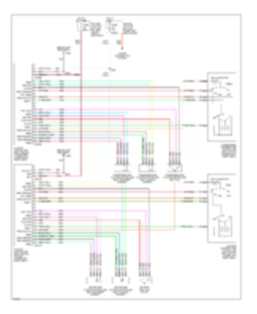
POWER SEATS
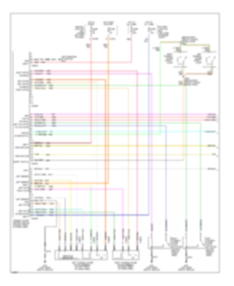
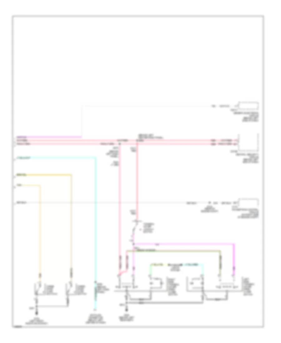
Heated Seats Wiring Diagram for Lincoln Blackwood 2003
List of elements for Heated Seats Wiring Diagram for Lincoln Blackwood 2003:
- (behind left rear seat)
- Bat
- Battery junction box (bjb) (on left side of eng compt)
- C270b
- C3031a
- C3031b
- C3036a
- C3036b
- Central junction box (cjb) (under left side of dash)
- Climate controlled seat module (driver) (under left front seat)
- Climate controlled seat module (passenger) (under right front seat)
- Cold
- Driver side climate controlled seat backrest element
- Driver side climate controlled seat cushion element
- Driver's seat fan motor
- Driver's temperature controlled seat switch (under left front seat)
- Fan tach
- Feed
- From switch
- Fuse 10a
- Fuse 30a
- G300
- Gnd
- Hot
- Hot at all times
- Hot in run
- Ign volt
- Motor
- Nca
- Not used
- Off
- On illumination
- Passenger side climate controlled seat backrest element
- Passenger side climate controlled seat cushion element
- Passenger side climate controlled seat fan
- Passenger's temperature controlled seat switch (under right front seat)
- Power distribution system
- Red
- Return
- S282
- S320
- S333
- S336
- Seat enable
- Tan/ red
- Temp +
- Temp -
- Temp sensor
- To fan
- To motor
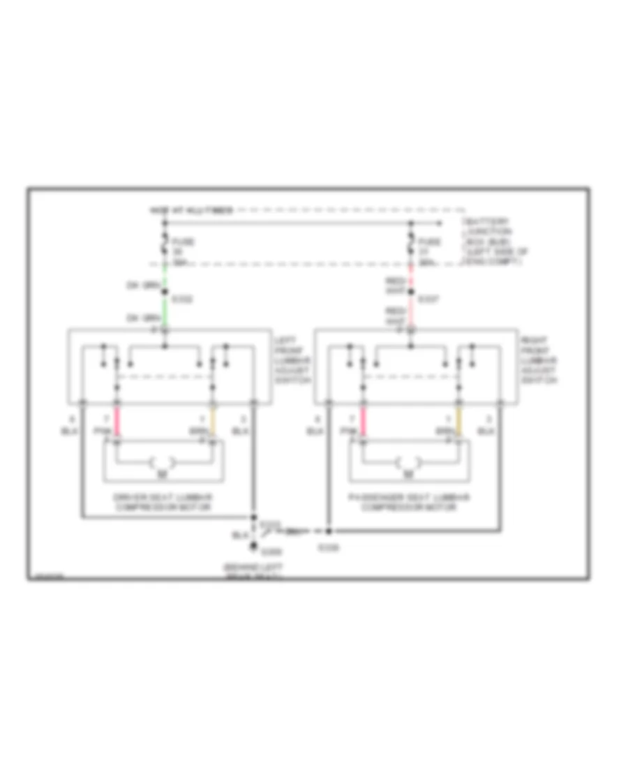
Lumbar Wiring Diagram for Lincoln Blackwood 2003
List of elements for Lumbar Wiring Diagram for Lincoln Blackwood 2003:
- (behind left rear seat)
- Battery junction box (bjb) (left side of eng compt)
- Driver seat lumbar compressor motor
- Fuse 30a
- G300
- Hot at all times
- Left front lumbar adjust switch
- Passenger seat lumbar compressor motor
- Pnk
- Right front lumbar adjust switch
- S332
- S333
- S336
- S337
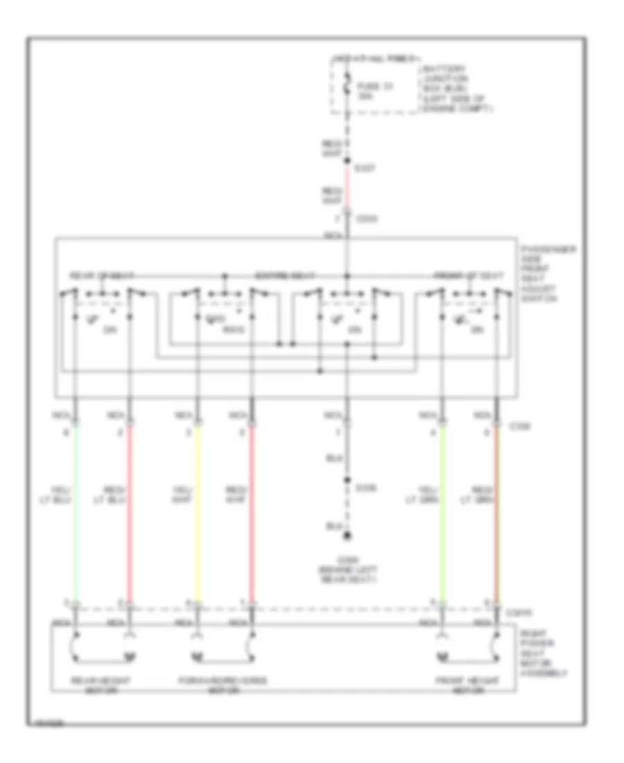
Passenger Seat Wiring Diagram for Lincoln Blackwood 2003
List of elements for Passenger Seat Wiring Diagram for Lincoln Blackwood 2003:
- Battery junction box (bjb) (left side of engine compt)
- C3015
- C330
- Entire seat
- Forward/reverse motor
- Front height motor
- Front of seat
- Fuse 31 30a
- Fwd
- G300 (behind left rear seat)
- Hot at all times
- Nca
- Passenger side front seat adjust switch
- Rear height motor
- Rear of seat
- Right power seat motor assembly
- Rwd
- S336
- S337
POWER TOP/SUNROOF
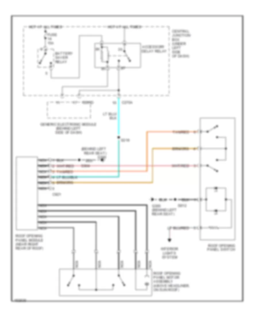
Moonroof Wiring Diagram for Lincoln Blackwood 2003
List of elements for Moonroof Wiring Diagram for Lincoln Blackwood 2003:
- (behind left rear seat) g300
- Accessory delay relay
- Battery saver relay
- C201d
- C270a
- C921
- Central junction box (under left side of dash)
- Fuse 15a
- G300 (behind left rear seat)
- Generic electronic module (behind left side of dash)
- Hot at all times
- Interior lights system
- Nca
- Roof opening panel module (near right rear of roof)
- Roof opening panel motor assembly (above headliner, on sun roof)
- Roof opening panel switch
- S219
- S904
- S912
- Tan/red
Power Tonneau Cover Wiring Diagram (1 of 2) for Lincoln Blackwood 2003
List of elements for Power Tonneau Cover Wiring Diagram (1 of 2) for Lincoln Blackwood 2003:
- (behind right side of loading space lining) s408
- (left rear end of vehicle) g401
- Battery junction box (left side of engine compt)
- C270a
- C270b
- C4053a
- C4053b
- C4053c
- C4054a
- C4054b
- C4054c
- C4054d
- C4057a
- C4057b
- Central junction box (under left side of dash)
- Cover motor
- Cover switch
- Crgo dr ajar
- Fuse 15a
- Fuse 50a
- Fuse 5a
- G401 (left rear end of vehicle)
- Gem
- Gnd
- Hot at all times
- Hot in run or start
- Hot in start
- Iso bus
- Left actuator
- Left motor
- Left motor
- Left motor right motor
- Left sensor
- Left tonneau cover latch actuator (on left rear of cargo area)
- Left tonneau cover motor assembly (on left front of cargo area)
- Left tonneau cover safety strip
- Nca
- Obstacle detector
- Red
- Right motor
- Right tonneau cover latch actuator (on right rear of cargo area)
- Right tonneau cover motor assembly (on right front of cargo area)
- Right tonneau cover safety strip
- Rt actuator
- S409
- S418
- S419
- Safety switch
- Solenoid
- Tan
- Tan/red
- Tonneau cover control module (on right front of cargo area)
- Top down
- Top up
- Vbatt
- Vss +
Power Tonneau Cover Wiring Diagram (2 of 2) for Lincoln Blackwood 2003
List of elements for Power Tonneau Cover Wiring Diagram (2 of 2) for Lincoln Blackwood 2003:
- (behind left center dash panel) s258
- (behind left dash panel)
- (front of roof)
- C175
- C201a
- C274b
- Cargo door ajar switch
- Cargo door ajar switch 2
- Central security module (behind left end of dash)
- Datalink connector (below left center of dash)
- G104 (left front radiator suport)
- G300 (behind left rear seat)
- Generic electronic module (behind left side of dash)
- Interior lights system
- Left side tonneau cover open/ close switch
- Powertrain control module (on right side of engine compt)
- Right side tonneau cover open/ close switch
- S143 (rear of engine compt)
- S229
- S278
- S911
- Tan
- Tonneau cover lockout switch
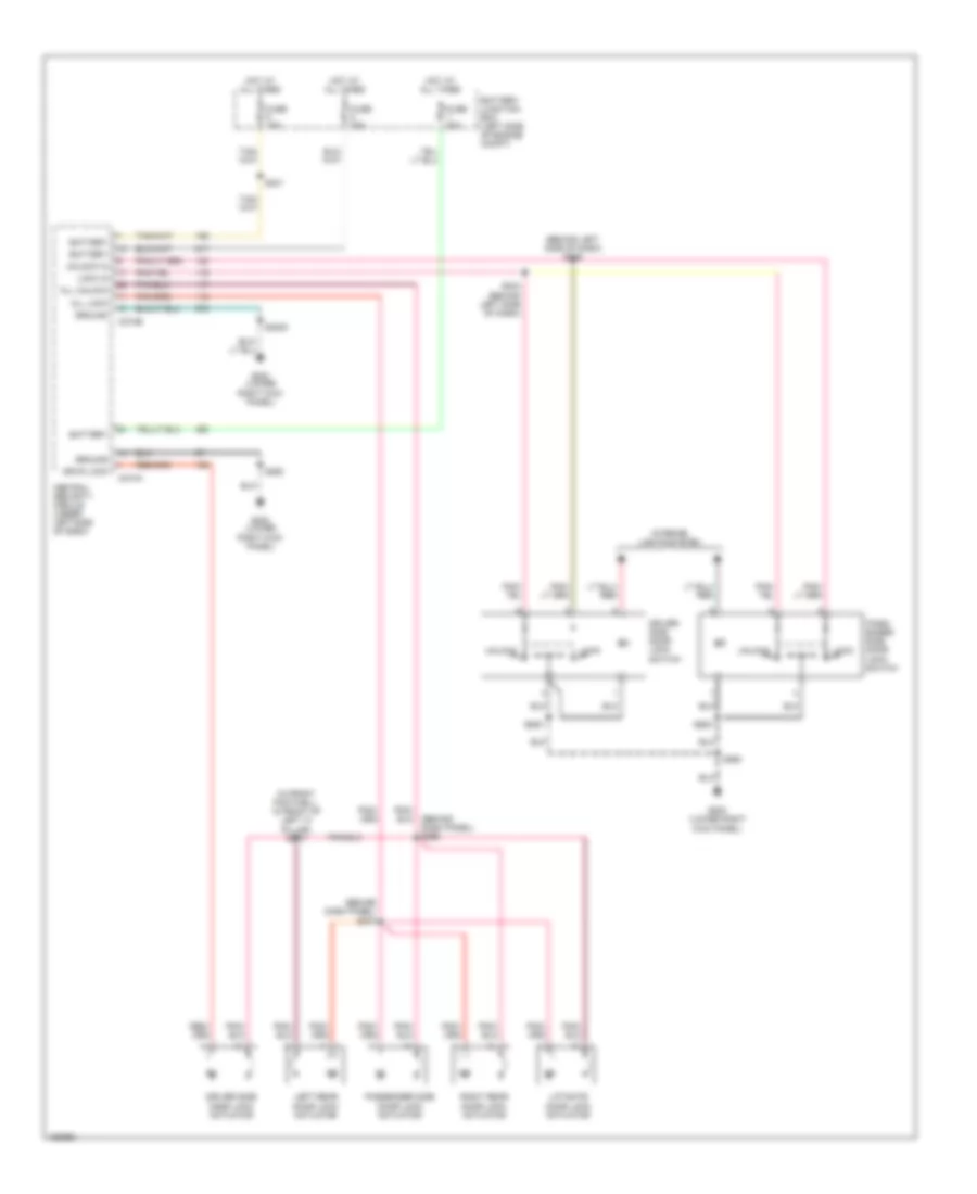
POWER WINDOWS
Power Windows Wiring Diagram for Lincoln Blackwood 2003
List of elements for Power Windows Wiring Diagram for Lincoln Blackwood 2003:
- 87a
- Acc delay relay
- Batt saver
- Battery junction box
- Battery saver relay
- C201d
- C270a
- C270b
- C504a
- C504b
- Central junction box
- Down sw input
- Fuse 15a
- Fuse 30a
- G200 (lower right kick panel)
- Generic electronic module
- Ground
- Hot at all times
- Interior lights system
- Left front power window
- Left front switch
- Left power window switch
- Left rear power window motor
- Left rear power window switch
- Left rear switch
- Lock out
- One tch dn hi
- One tch dn lo
- One touch down
- One touch down relay
- Otd sw input
- Right front power window motor
- Right front power window switch
- Right front switch
- Right rear power window motor
- Right rear power window switch
- Right rear switch
- S205
- S219
- S263 (behind dash panel)
- S271
- S272 (behind left side of dash)
- S600
- S701
- S801
- Shunt (0.015 +/- 0.001 ohm)
RADIO
Radio Wiring Diagram for Lincoln Blackwood 2003
List of elements for Radio Wiring Diagram for Lincoln Blackwood 2003:
- (dash harn, near break- out to console blower motor)
- (dash harn, near break- out to torque on demand switch) s324
- (lower right kick panel) g200
- (main harn, behind left side of dash)
- Air bag sliding contact
- Amp l rear (+)
- Amp r rear (+)
- Audio network
- Audio on
- Audio shield
- Audio system on
- Audio sytem on
- Band
- Body computer system
- C122
- C270a
- C270b
- C290a
- C290b
- C290c
- C3041
- C349a
- Cd changer
- Cd left sig in
- Cd left sig out
- Cd player shield
- Cd right sig in
- Cd right sig out
- Central junction box (under left side of dash)
- Delayed acc power
- Dwn
- Fuse 10a
- Fuse 25a
- Fused ignition
- G200 (lower right kick panel)
- G202 (upper left kick panel)
- Generic electronic module
- Ground
- High audio mute
- Hot at all times
- Illum
- Interior lights
- Interior lights system
- L front spkr feed
- L rear sig (+)
- L rear sig (-)
- L rear spkr feed
- Left front door speaker
- Left rear door speaker
- Left sig (+)
- Left sig (-)
- Mem
- Nca
- Power
- Protocol a
- Protocol b
- R front spkr feed
- R rear sig (+)
- R rear sig (-)
- R rear spkr feed
- Radio
- Radio control
- Rear integrated control panel
- Right front door speaker
- Right rear door speaker
- Right sig (+)
- Right sig (-)
- S200
- S203
- S233
- S255
- S285
- S322
- S325
- S327
- S328
- S329
- Shield
- Speed control servo (left side of engine compt)
- Starting system
- Steering wheel radio switch
- Sub speaker
- Subwoofer
- Subwoofer (+)
- Subwoofer (-)
- Subwoofer amplifier
- Tan
- Vehicle speed sig
- Vss
SHIFT INTERLOCK
Shift Interlock Wiring Diagram for Lincoln Blackwood 2003
List of elements for Shift Interlock Wiring Diagram for Lincoln Blackwood 2003:
- Auto park brake release diode
- Auto park brake release solenoid (behind center of dash)
- Auto park brake release switch (on steering column)
- Battery junction box (left side of engine compt)
- Brake pedal position switch (under left side of dash)
- Brake shift interlock (on steering column)
- C220a
- C270a
- C270b
- Central junction box (under left side of dash)
- Exterior lights system
- Fuse 15 5a
- Fuse 6 5a
- G200 (lower right kick panel)
- G201 (lower left kick panel)
- Hot at all times
- Hot in run
- Instrument cluster
- Parking brake switch (right side of park brake lever)
- Rfi module (near steering column)
- S2001
- S204
- S208
- S252
- S291
- S297 (behind left side of dash)
- Solid state
STARTING/CHARGING
Charging Wiring Diagram for Lincoln Blackwood 2003
List of elements for Charging Wiring Diagram for Lincoln Blackwood 2003:
- Acc
- Battery
- Battery junction box (bjb) (left side of engine compt)
- C102a
- C102b
- C102c
- C220a
- C270b
- Central junction box (cjb) (under left side of dash)
- Charge gauge
- Early production
- Fuse 2oa
- Fuse 30a
- Fuse 40a
- G105 (left side of eng compt)
- G106 (left side of eng compt)
- G107 (right side of eng compt)
- Generator
- Ignition switch
- Instrument cluster
- Lock
- Off
- Red
- Run
- S214
- S237
- Start
- Starter motor
- Starter motor relay (right rear of engine compt)
Starting Wiring Diagram for Lincoln Blackwood 2003
List of elements for Starting Wiring Diagram for Lincoln Blackwood 2003:
- (rear of eng compt)
- Acc
- Battery
- Battery junction box (bjb) (left side of engine compt)
- C270b
- Central junction box (cjb) (under left side of dash)
- Charging circuit
- Digital transmission range (dtr) sensor (left side of transmission)
- Fuse 15a
- Fuse 40a
- G105 (left side of engine compt)
- G106 (left side of engine compt)
- G107 (right side of engine compt)
- Ignition switch
- Lock
- Off
- Power distribution system
- Red
- Run
- S214
- Sound systems
- Sta
- Start
- Starter motor
- Starter relay (right rear of engine compt)
- Tan/red
- Tan/red s179
SUPPLEMENTAL RESTRAINTS
Supplemental Restraints Wiring Diagram for Lincoln Blackwood 2003
List of elements for Supplemental Restraints Wiring Diagram for Lincoln Blackwood 2003:
- (behind left side dash panel) s237
- (not used)
- (under left side of dash, at base of left "a" pillar) g201
- Air bag indicator
- Air bag indicator ctrl
- Air bag sliding contact
- Air bag tone driver
- C201a
- C2041a
- C2041b
- C220a
- C270a
- C270b
- Central junction box (cjb) (under left side of dash)
- Data link connector (dlc) (partial) (below left center of dash)
- Dedicated ground
- Driver air bag unit
- Driver safety belt retractor pretensioner (near base of left "b" pillar)
- Feed
- Fuse f2.22 10a
- Fuse f2.30 30a
- Generic electronic module (gem) (behind left side of dash)
- Hot in run
- Hot in run or start
- Ignition
- Instrument cluster
- Iso bus
- Left side air bag module
- Left side air bag sensor (beneath left front seat)
- Nca
- Passenger air bag module
- Passenger safety belt retractor pretensioner (near base of right "b" pillar)
- Pin shorting bar is engaged when module connector is disconnected from harness (shorting bar is connected between pins: 20-21 conn. c2041a 2-3 & 5-6 conn. c2041b)
- Restraints control module (behind right center of dash)
- Return
- Right side air bag module
- Right side air bag sensor (beneath right front seat)
- S229 (behind left side dash panel)
- Shorting bar
TRANSMISSION
A/T Wiring Diagram for Lincoln Blackwood 2003
List of elements for A/T Wiring Diagram for Lincoln Blackwood 2003:
- (below left center
- (left kick panel) g201
- (left side of transmission) turbine shaft speed sensor
- (rear of engine compt)
- (rear of engine compt) g101
- (right side of engine compt) powertrain control module
- (under left side of dash) rfi module
- Abs module, speed control servo
- Air suspension control module, central security module, brake shift interlock
- Autolamp sensor, central security module, tonneau cover control module
- Automatic transmission
- Battery junction box (left side of engine compt)
- Bpp
- Brake pedal position switch (on brake pedal bracket)
- Brake pressure switch
- C175
- C270b
- Ccs
- Central junction box (under left side of dash)
- Cht
- Coast clutch solenoid
- Compt)
- Cylinder head temperature (cht) sensor (top right rear of engine)
- Data
- Digital transmission range sensor
- Dlc (+)
- Dlc (-)
- Ect
- Electronic pressure control solenoid
- Engine controls system
- Engine coolant temperature sensor (left front of engine)
- Epc
- Fuse 15a
- Fuse 30a
- Fuse 5a
- G104 (left front radiator support)
- Ground
- Hot at all times
- Hot in run or start
- Iat
- Ignition coils, ignition capacitors
- Instrument cluster, pats transceiver module
- Intake air temperature sensor (on intake manifold)
- Nca
- Ocs
- Ocs illum
- Of dash)
- Of dash) data link connector
- Oss
- Output shaft speed sensor (left side of transmission)
- Overdrive cancel switch (ocs) (end of transmission selector lever)
- Pcm power diode
- Pcm power relay
- R p
- Red
- S1003 (left side of engine compt)
- S101
- S106
- S116
- S127 (rear of engine compt)
- S135 (right side of engine)
- S136
- S137
- S138
- S140
- S141
- S155 (rear of engine compt)
- S156
- S157
- S208
- S225
- S237
- S291
- Shift solenoid 1
- Shift solenoid 2
- Sig rtn
- Ss 1
- Ss 2
- Tcc
- Tft
- Throttle position (tp) sensor (on throttle body)
- Torque converter clutch solenoid
- Tr1
- Tr2
- Tr3a
- Tr4
- Transmission fluid temperature sensor
- Tss
- Vpwr
- Vref
WARNING SYSTEMS
Warning Systems Wiring Diagram for Lincoln Blackwood 2003
List of elements for Warning Systems Wiring Diagram for Lincoln Blackwood 2003:
- Auto
- Bat
- Battery junction box (left side of engine compt)
- C201a
- C201c
- C205a
- C220b
- C4054c
- Central junction box (under left side of dash)
- Driver side front door ajar switch
- Driver side rear door ajar switch
- Fuse 15a
- Fuse 5a
- G200 (lower right kick panel)
- G201 (lower left kick panel)
- G300 (behind left rear seat)
- Generic electronic module (gem) (behind left side of dash)
- Head
- Hot at all times
- Hot in acc or run
- Hot in run
- Ign
- Instrument cluster
- Key warning switch
- Main light switch
- Nca
- Off
- Park
- Passenger side front door ajar switch
- Passenger side rear door ajar switch
- S208
- S241
- S333
- S500
- S600
- S701
- S801
- Safety belt buckle switch (in seat belt buckle)
- Seat belt ind
- Tonneau cover control module (right front of cargo area)
WIPER/WASHER
Wiper/Washer Wiring Diagram for Lincoln Blackwood 2003
List of elements for Wiper/Washer Wiring Diagram for Lincoln Blackwood 2003:
- 103k ohms
- 3.3k ohms
- 4.08k ohms
- 7.25k
- 87a
- Battery junction box (left side of engine compt)
- C1026
- C201a
- C202b
- C239
- Central junction box (under left side of dash)
- Front washer pump ctrl
- Fuse 30a
- G102 (rear of right fender apron)
- G103 (right front of engine compartment)
- Generic electronic module (behind left side of dash)
- Hot in acc or run
- Int max
- Int min
- Interval delay/wash
- Multi- function switch
- Off
- Off 36.27k ohms
- Ohms
- Park
- Park sense
- Red
- Run
- Run/park relay ctrl
- S102
- S103
- S113
- S146 (near breakout to left fog lamp)
- Signal return
- Tan/ red
- Washer pump assembly (in fluid reservoir)
- Washer pump relay
- Washer switch
- Wind- shield wiper motor
- Wiper high/low relay
- Wiper mode select
- Wiper run/park relay
- Wiper speed ctrl
- Wiper switch

 Čeština
 Deutsch
 Ελληνικά
 English
 English
 Español
 Suomi
Suomi Français
 Français
 עברית
עברית Hrvatski
 Magyar
 Italiano
 日本語
日本語 한국어
한국어 Nederlands
 Polski
 Português
 Português
 Română
 Русский
 Slovenčina
 Slovenščina
 Svenska
 Türkçe
 中文 (中国)