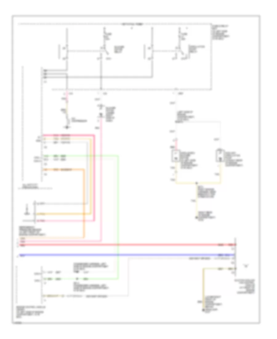
AIR CONDITIONING
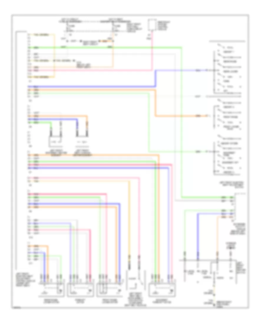
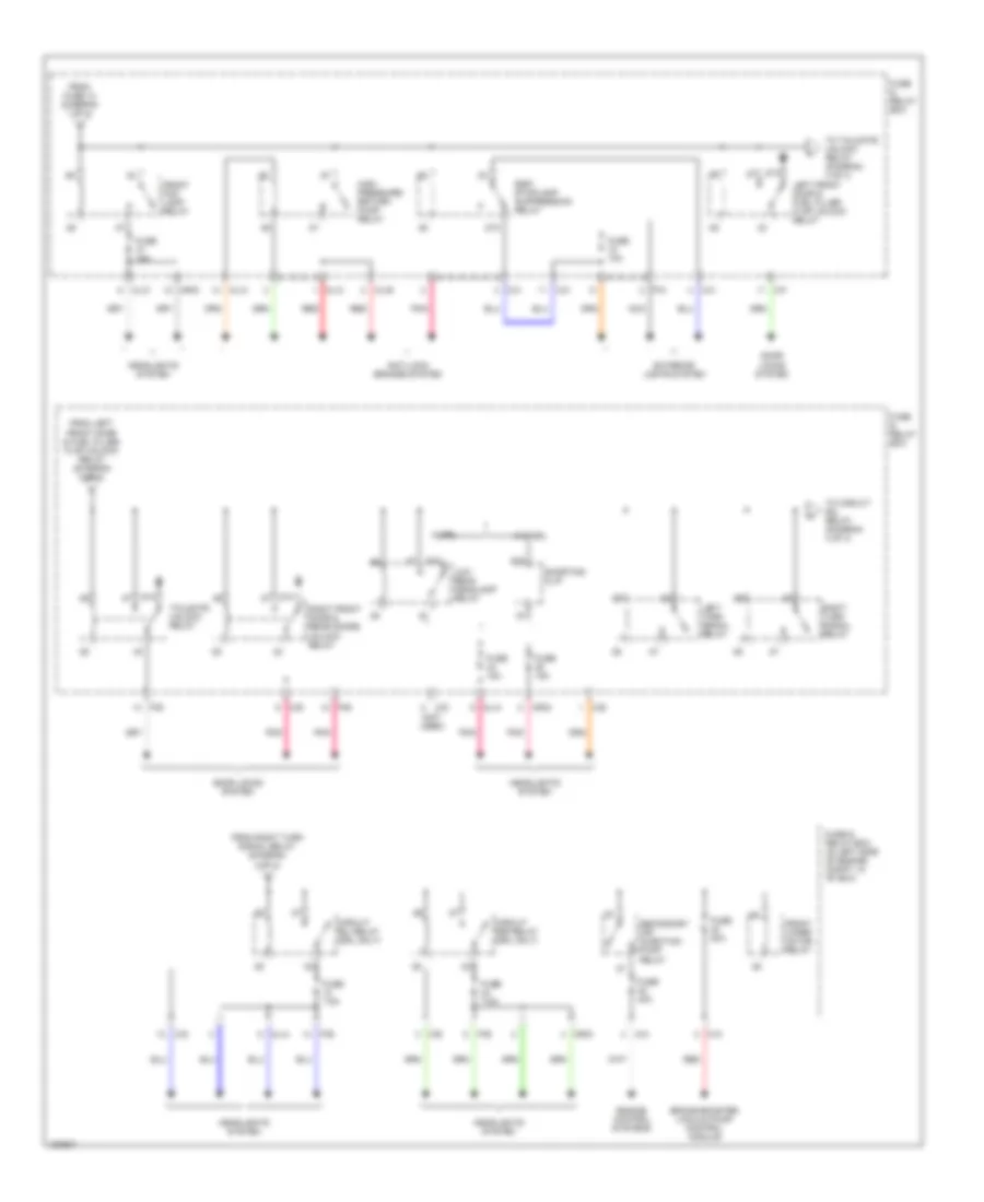
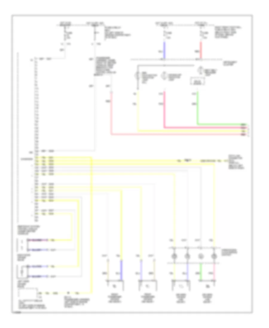
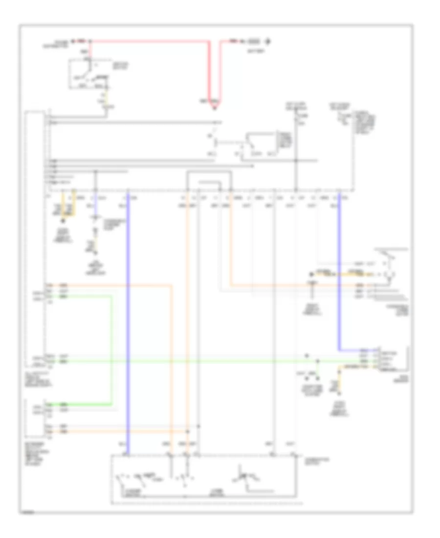
Manual A/C Wiring Diagram, with Coolant Fan Control Module (1 of 2) for Mercedes-Benz ML320 2001
 https://portal-diagnostov.com/license.html
Automotive Electricians Portal FZCO
Automotive Electricians Portal FZCO
https://portal-diagnostov.com/license.html
https://portal-diagnostov.com/license.html
Automotive Electricians Portal FZCO
Automotive Electricians Portal FZCO
List of elements for Manual A/C Wiring Diagram, with Coolant Fan Control Module (1 of 2) for Mercedes-Benz ML320 2001:
- (below passenger's side of cockpit, behind kick panel) g203
- (cockpit harness, center, in breakout for a/c control module) z50/29
- (cockpit harness, right side, near breakout for icing sensor) z50/4
- 2406/6406
- 2409/6409
- 2411/6411
- 2412/6412
- 2413/6413
- 2415/6415
- 2418/6418
- 2419/6419
- 2420/6420
- 2422/6422
- 2432/6432
- 2433/6433
- 2437/6437
- 2445/6445
- A/c on switch
- A/c pushbutton control module
- Blend air flap actuator motor (behind right side of dash)
- Blower motor preresistor group (under right side of dash, in blower assembly)
- Blower switch
- C/c
- Exhaust ventilator auxiliary fuse (right rear of engine compartment)
- Freeze protection temperature sensor (behind right side of dash, in evaporator)
- Fresh
- Fuse & relay box (in left side of engine compartment, in "e" box)
- Fuse 15a
- Fuse 70a
- Gnd
- Heater a/c switch
- High
- Hot at all times
- Hot in on or start
- Illumination
- In-car temperature sensor (behind center of dash)
- In-car temperature sensor aspirator blower (behind center of dash)
- Interior lights system
- Low
- Med 1
- Med 2
- Mr/e
- Mtr ctrl
- Nca
- Off
- Outside temperature sensor (behind lower right side of dash)
- Pnk
- Recirc
- Recirculated air flap element (behind right side of dash)
- Recirculated air switch
- Red
- Tan
- Temperature regulator
- Vref
- Z50/2 (cockpit harness, center, near breakout for a/c control module)
- Z50/3 (cockpit harness, near breakout for passenger harness to cockpit harness interconnect)
- Z50/30 (cockpit harness, center, near breakout for a/c control module)
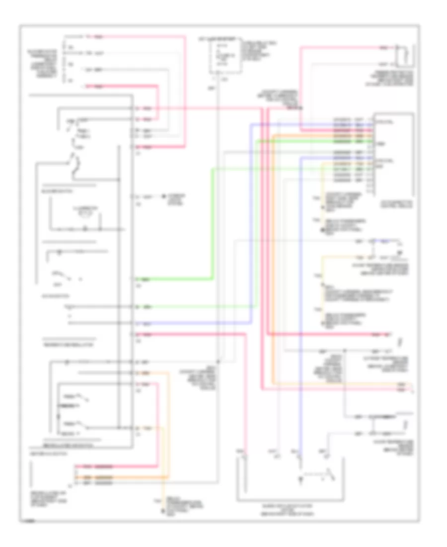
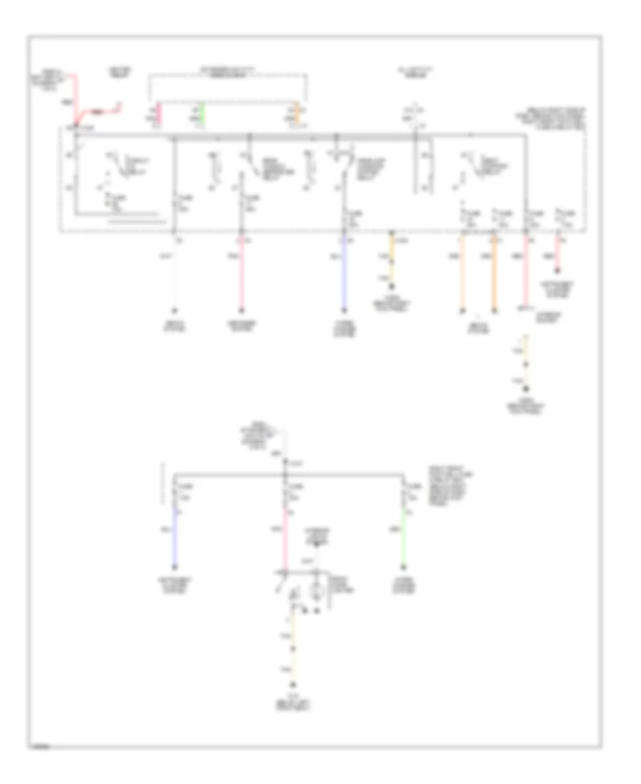
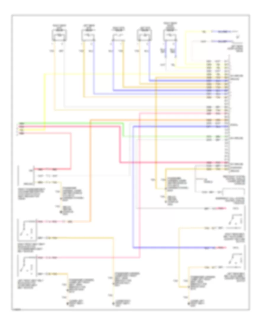
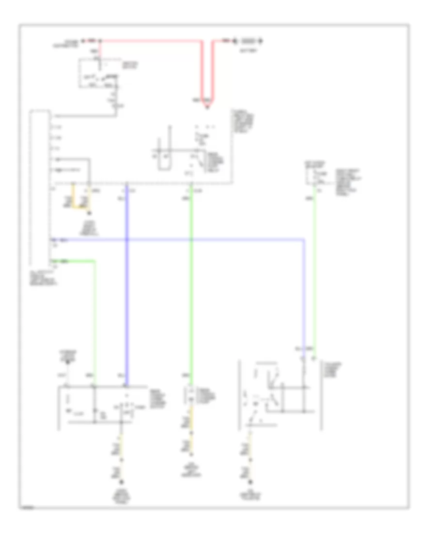
Manual A/C Wiring Diagram, with Coolant Fan Control Module (2 of 2) for Mercedes-Benz ML320 2001
List of elements for Manual A/C Wiring Diagram, with Coolant Fan Control Module (2 of 2) for Mercedes-Benz ML320 2001:
- (left side of engine compartment, in "e" box) z57-2
- (lower right front of engine compartment, behind headlamp) g107
- (passenger harness, left side of engine compartment in "e" box) z51/3
- (right rear of engine compartment) g105
- 170/7170
- 171/7171
- 172/7172
- 2081/8457 (or 2203)
- 2081/8547 (or 2203)
- 2415/6415
- 87a
- A/c compressor
- A12
- All activity module (aam)
- B12
- Blower motor (under right side of dash)
- Blower motor relay
- C/g
- Can h
- Can l
- Circulation pump relay
- Coolant circulation pump (in right rear of engine compartment)
- Engine control module (me-sfi) (in left side of engine compartment, in "e" box)
- Fuse & relay box (in left side of engine compartment, in "e" box)
- Fuse 25a
- Fuse 30a
- Gnd
- Hot at all times
- M/a
- Module box blower motor (in left side of engine compartment, in "e" box)
- Mr/f
- Pnk
- Red
- Refrigerant pressure sensor (in left front of engine compartment)
- Suction cooling fan control module (at front of engine compartment)
- Tan
- Z51/4 (passenger harness, left side of engine compartment, in "e" box)
- Z57/3 (right engine harness, near breakout for wiper motor)
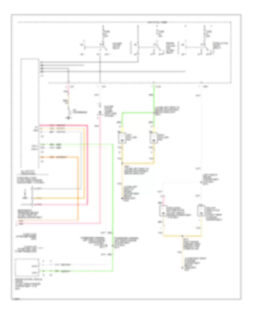
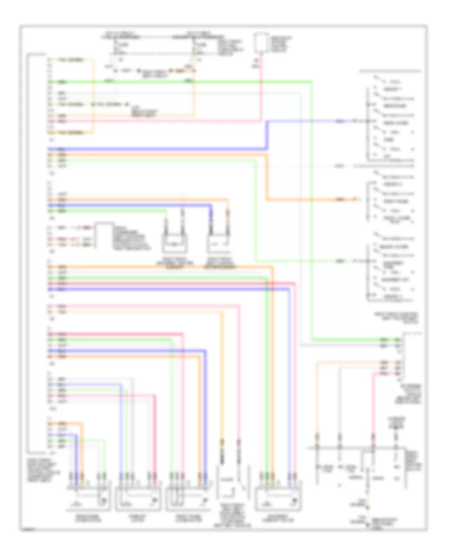
Manual A/C Wiring Diagram, without Coolant Fan Control Module (1 of 2) for Mercedes-Benz ML320 2001
List of elements for Manual A/C Wiring Diagram, without Coolant Fan Control Module (1 of 2) for Mercedes-Benz ML320 2001:
- (below passenger's side of cockpit, behind kick panel) g203
- (cockpit harness, center, in breakout for a/c control module) z50/29
- (cockpit harness, right side, near breakout for icing sensor) z50/4
- 2406/6406
- 2409/6409
- 2411/6411
- 2412/6412
- 2413/6413
- 2415/6415
- 2418/6418
- 2419/6419
- 2420/6420
- 2422/6422
- 2432/6432
- 2433/6433
- 2437/6437
- 2445/6445
- A/c on switch
- A/c pushbutton control module
- Blend air flap actuator motor (behind right side of dash)
- Blower motor preresistor group (under right side of dash, in blower assembly)
- Blower switch
- C/c
- Freeze protection temperature sensor (behind right side of dash, in evaporator)
- Fresh
- Fuse & relay box (in left side of engine compartment, in "e" box)
- Fuse 16 15a
- Gnd
- Heater a/c switch
- High
- Hot in on or start
- Illumination
- In-car temperature sensor (behind center of dash)
- In-car temperature sensor aspirator blower (behind center of dash)
- Interior lights system
- Low
- Med 1
- Med 2
- Mtr ctrl
- Nca
- Off
- Outside temperature sensor (behind lower right side of dash)
- Pnk
- Recirc
- Recirculated air flap element (behind right side of dash)
- Recirculated air switch
- Tan
- Temperature regulator
- Vref
- Z50/2 (cockpit harness, center, near breakout for a/c control module)
- Z50/3 (cockpit harness, near breakout for passenger harness to cockpit harness interconnect)
- Z50/30 (cockpit harness, center, near breakout for a/c control module)
Manual A/C Wiring Diagram, without Coolant Fan Control Module (2 of 2) for Mercedes-Benz ML320 2001
List of elements for Manual A/C Wiring Diagram, without Coolant Fan Control Module (2 of 2) for Mercedes-Benz ML320 2001:
- (left side of engine compartment, in "e" box) z57-2
- (lower left front of engine compartment, behind headlamp) g106
- (lower left front of engine compartment, behind headlamp) z56/2
- (lower right front of engine compartment, behind headlamp) g107
- (passenger harness, left side of engine compartment, in "e" box) z51/3
- (passenger harness, left side of engine compartment, in "e" box) z51/4
- 170/7170
- 171/7171
- 172/7172
- 2415/6415
- 2607/3401
- 2608/3411
- 87a
- A/c compressor
- A12
- All activity module (aam)
- B12
- Blower motor (under right side of dash)
- Blower motor relay
- C/g
- Can h
- Can l
- Circulation pump relay
- Coolant circulation pump (in right rear of engine compartment)
- Engine control module (me-sfi) (in left side of engine compartment, in "e" box)
- Engine cooling fan stage 1 relay
- Fuse & relay box (in left side of engine compartment, in "e" box)
- Fuse 25a
- Fuse 30a
- Gnd
- Hot at all times
- Left auxiliary fan
- M/a
- Ml/b
- Ml320/ ml430 (after september 2000)
- Ml320/ml430 (after april 2000 to september 2000)
- Module box blower motor (in left side of engine compartment, in "e" box)
- Mr/f
- Pnk
- Red
- Refrigerant pressure sensor (in left front of engine compartment)
- Right auxiliary fan
- Tan
- Z56/1 (lower left front of engine compartment, behind headlamp)
- Z57/3 (right engine harness, near breakout for wiper motor)
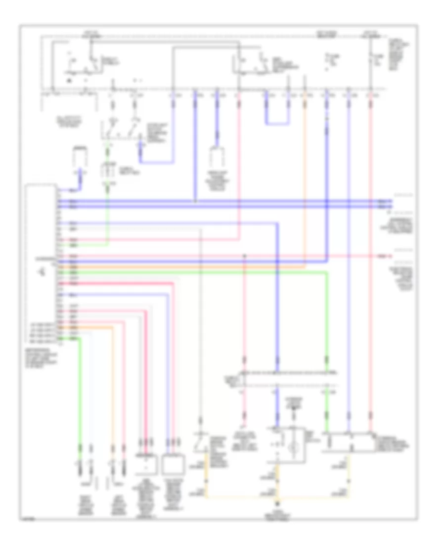
ANTI-LOCK BRAKES
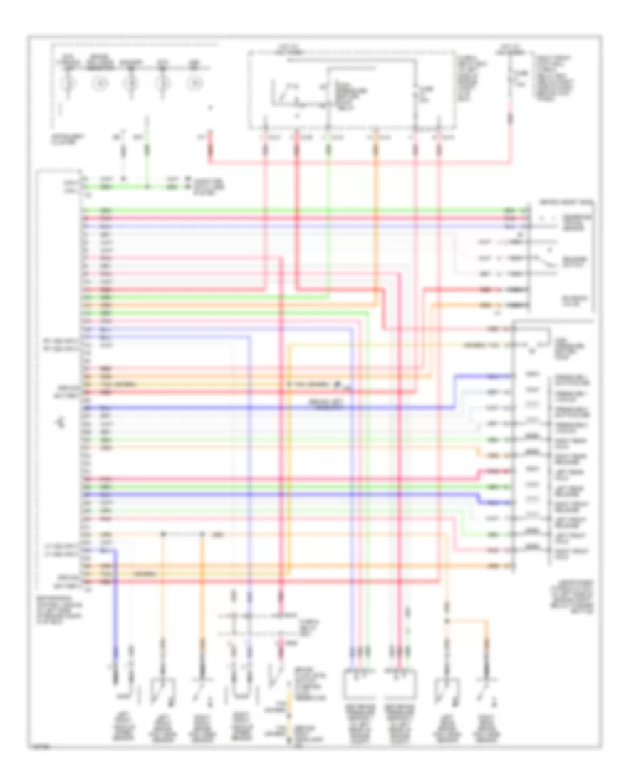
Anti-Lock Brakes Wiring Diagram (1 of 2) for Mercedes-Benz ML320 2001
List of elements for Anti-Lock Brakes Wiring Diagram (1 of 2) for Mercedes-Benz ML320 2001:
- (behind left headlamp)
- (behind right headlamp) w2
- A11
- Abs mil
- Asr/ets/esp hydraulic unit (in left side of engine compt, below washer bottle)
- B10
- Bas/esp mil
- Battery
- Brake assist (bas)
- Brake fluid level switch (in brake fluid reservoir)
- Brake pad wear indicator
- Can h
- Can l
- Computer data lines system
- Esp brake pressure sensor 1 (in left rear of engine compt)
- Esp brake pressure sensor 2 (in left rear of engine compt)
- Esp/sps/bas control module (in left side of engine compt, in "e" box)
- Ets mil
- Ets warning lamp
- Fuse & relay box
- Fuse & relay box (in left side of engine compt, in "e" box)
- Fuse 40a
- Fuse 7.5a
- Ground
- High pressure/ return pump
- High- pressure/ return pump relay
- Hot at all times
- Instrument cluster
- Left front brake pad wear sensor
- Left front hold
- Left front release
- Left front vehicle speed sensor
- Left rear brake pad wear sensor
- Left rear hold
- Left rear release
- Lf vss input
- Membrane travel sensor
- Ml/a
- Ml/b
- Ml/c
- Mr/b
- Nca
- Pnk
- Pressure 1 switchover
- Pressure 1 vacuum
- Pressure 2 switchover
- Pressure 2 vacuum
- Red
- Release switch
- Rf vss input
- Right front brake pad wear sensor
- Right front footwell fuse & relay box (below right side of dash, behind kick panel)
- Right front hold
- Right front release
- Right front vehicle speed sensor
- Right rear brake pad wear sensor
- Right rear hold
- Right rear release
- Solenoid valve
- Tan
Anti-Lock Brakes Wiring Diagram (2 of 2) for Mercedes-Benz ML320 2001
List of elements for Anti-Lock Brakes Wiring Diagram (2 of 2) for Mercedes-Benz ML320 2001:
- 87a
- Abs lateral acceleration sensor (below center console, behind shift assembly)
- All activity module (aam) (in "e" box)
- C/b
- C/c
- C/d
- C/e
- C/f
- C/h
- C1 a1
- Circuit 15 relay
- Data link connector (dlc) (below left side of dash)
- Diagnosis
- Electronic selector lever control module (w/a/t)
- Emergency call system control module (if equipped)
- Esp off switch
- Esp/ stoplamp suppression relay
- Esp/sps/bas control module (in left side of engine compt, in "e" box)
- Fuse & relay box
- Fuse & relay box (in left side of engine compt, in "e" box)
- Fuse 10a
- Fuse 15a
- Gnd
- Headlamp range adjustment control module
- Hot at all times
- Hot in run or start
- Interior lights system
- Left rear vehicle speed sensor
- Lr vss input
- Nca
- P/b
- P/c
- P/d
- Parking brake switch (on parking brake support bracket)
- Pnk
- Radio
- Red
- Right rear vehicle speed sensor
- Rr vss input
- Signal
- Steering angle sensor (below driver's side of dash)
- Stoplight switch (on brake pedal support)
- W29/2 (behind right kick panel)
- Yaw rate sensor (below center console, behind shift assembly)
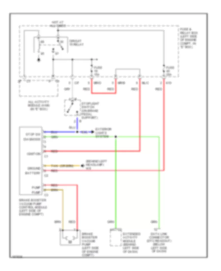
Brake Assist Wiring Diagram for Mercedes-Benz ML320 2001
List of elements for Brake Assist Wiring Diagram for Mercedes-Benz ML320 2001:
- (behind left headlamp) w9
- A4 c3
- All activity module (aam) (in "e" box)
- Battery
- Brake booster vacuum pump (left side of engine compt)
- Brake booster vacuum pump control module (left side of engine compt)
- C/f
- Circuit 15 relay
- Data link connector (dtc readout) (below left side of dash)
- Diagnosis
- Extended activity module (behind left side of dash)
- Exterior lights system
- Fuse & relay box (left side of engine compt, in "e" box)
- Fuse 15a
- Fuse 20a
- Ground
- Hot at all times
- Ignition
- K10
- Ml/c
- Mr/b
- Mr/d
- Pump
- Red
- Stop sw
- Stoplight switch (on brake pedal support)
- Tan
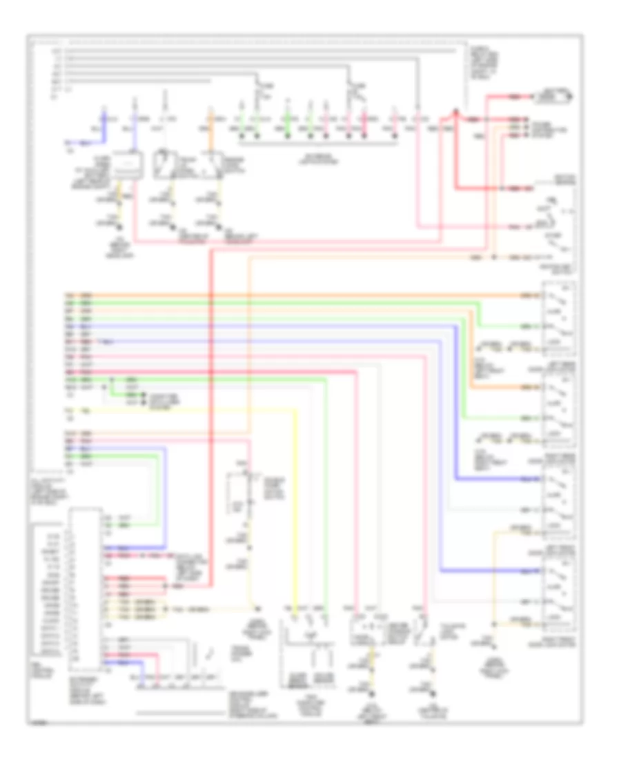
ANTI-THEFT
Anti-theft Wiring Diagram, with Auxiliary Alarm for Mercedes-Benz ML320 2001
List of elements for Anti-theft Wiring Diagram, with Auxiliary Alarm for Mercedes-Benz ML320 2001:
- 15c
- A c1
- A10
- A12
- Acc
- Ajar
- Alarm siren (w/ auxiliary battery) (left rear of engine compt)
- All activity module (left side of engine compt, in "e" box)
- Ata ind
- B11
- B12
- Battery
- C/d
- C/e
- C3 c
- Center console switch group
- Clock
- Computer data lines system
- Cruise
- Data 1
- Data 2
- Data 3
- Data 4
- Data link connector (below left side of dash)
- Diag
- Door lock
- Double combi- nation switch
- Engine hood switch
- Extended activity module (behind left side of dash)
- Exterior lights system
- Fbm control module
- Fuse & relay box (left side of engine compt, in "e" box)
- Fuse 7.5a
- Glass break sensor
- Ignition key switch
- Ignition switch
- Immob
- Incline sensor
- Inhibit
- Ki 15
- Ki 15c
- Ki 30
- Ki 31
- Left front door lock motor
- Left front seat)
- Left rear door lock motor
- Lock
- Mb-immobilizer control module (right side of steering column)
- Ml/a
- Ml/c
- Mr/a
- Mr/b
- Mr/d
- Off
- On/off
- P/d
- P/e
- Pnk
- Power distribution system
- Red
- Right front door lock motor
- Right kick panel)
- Right rear door lock motor
- Run
- Start
- Tailgate lock motor
- Tan
- Trans- ponder coil
- Trip computer control module
- Trunk lid micro switch
- W18 (below
- W18 (below left front seat)
- W19 (below right front seat)
- W2 (behind right headlamp)
- W29/2 (behind
- W8 (center of tailgate)
- W9 (behind left headlamp)
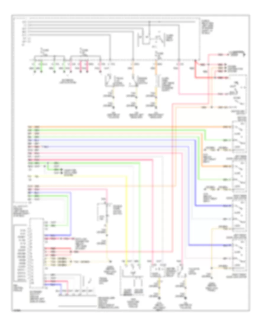
Anti-theft Wiring Diagram, without Auxiliary Alarm for Mercedes-Benz ML320 2001
List of elements for Anti-theft Wiring Diagram, without Auxiliary Alarm for Mercedes-Benz ML320 2001:
- 15c
- A c1
- A10
- A12
- Acc
- Ajar
- Alarm horn (left rear corner of engine compt)
- Alarm horn relay
- All activity module (left side of engine compt, in "e" box)
- Ata ind
- B11
- B12
- Battery
- C c3
- C/d
- C/e
- Center console switch group
- Clock
- Computer data lines system
- Cruise
- Data 1
- Data 2
- Data 3
- Data 4
- Data link connector (below left side of dash)
- Diag
- Door lock
- Double combi- nation switch
- Engine hood switch
- Extended activity module (behind left side of dash)
- Exterior lights system
- Fbm control module
- Fuse & relay box (left side of engine compt, in "e" box)
- Fuse 20a
- Fuse 7.5a
- Glass break sensor
- Ignition key switch
- Ignition switch
- Immob
- Incline sensor
- Inhibit
- Ki 15
- Ki 15c
- Ki 30
- Ki 31
- Left front door lock motor
- Left front seat)
- Left rear door lock motor
- Lock
- Mb-immobilizer control module (right side of steering column)
- Ml/a
- Mr/a
- Mr/d
- Off
- On/off
- P/d
- P/e
- Pnk
- Power distribution system
- Red
- Right front door lock motor
- Right kick panel)
- Right rear door lock motor
- Run
- Start
- Tailgate lock motor
- Tan
- Trans- ponder coil
- Trip computer control module
- Trunk lid micro switch
- W18 (below
- W18 (below left front seat)
- W19 (below right front seat)
- W2 (behind right headlamp)
- W29/2 (behind
- W8 (center of tailgate)
- W9 (behind left headlamp)
BODY CONTROL MODULES
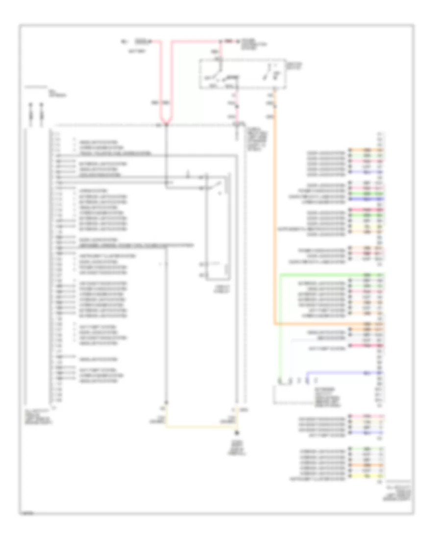
All Activity Module Wiring Diagram for Mercedes-Benz ML320 2001
List of elements for All Activity Module Wiring Diagram for Mercedes-Benz ML320 2001:
- 15c
- A10
- A11
- A12
- Acc
- Air conditioning system
- All activity module (left side of engine compt)
- Anti-theft system
- B10
- B11
- B12
- Battery
- C/d
- Circuit 15 relay
- Computer data lines system
- Cooling fans system
- Defogger, mirrors, power tops, power windows systems
- Door locks system
- Extended activity module (eam) (behind left side of dash)
- Exterior lights system
- Fuse & relay box (left side of engine compt, in "e" box)
- Headlights system
- Horns system
- Ignition switch
- Instrument cluster system
- Interior lights system
- Key in
- Mr/d
- Nca
- Off
- Pnk
- Power distribution system
- Power windows system
- Rcl antenna
- Red
- Run
- Seats system
- Start
- Tan
- Trunk, tailgate, fuel doors system
- W16/4 (right side of firewall)
- Wiper/washer system
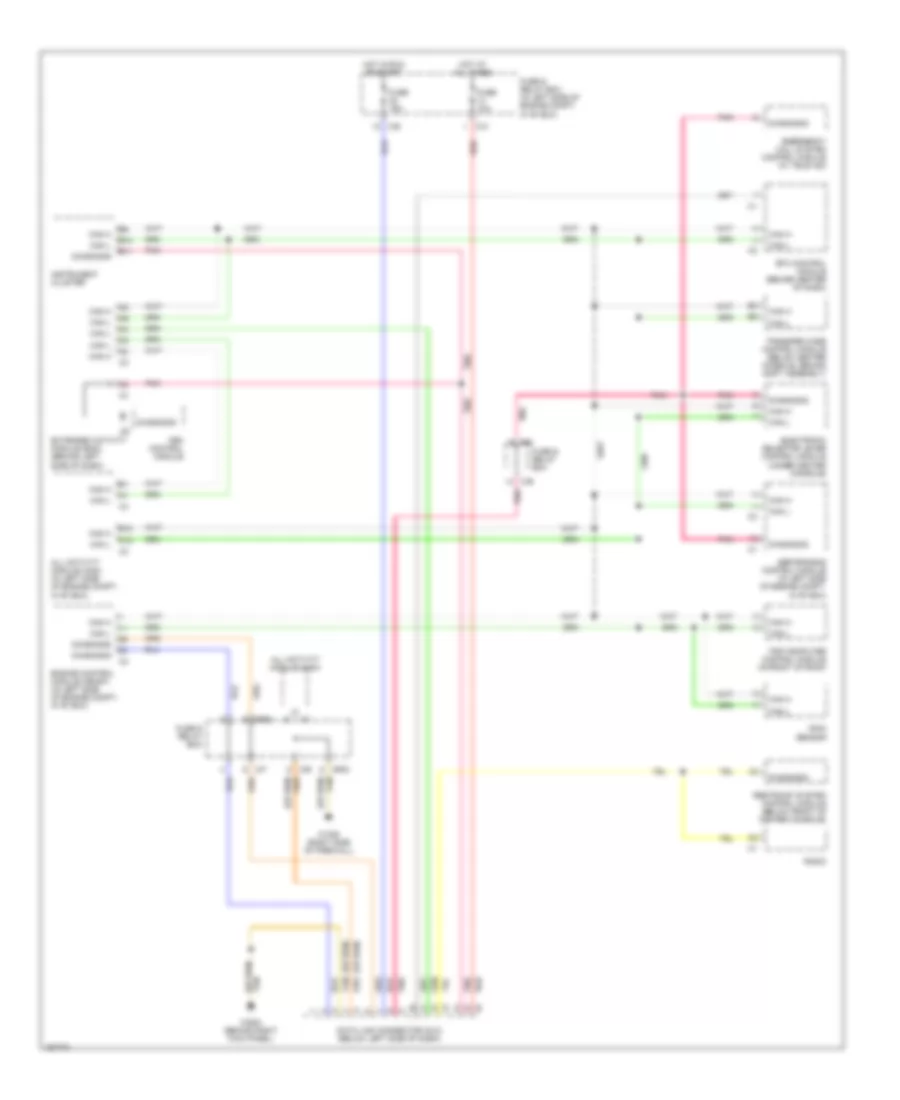
Extended Activity Module Wiring Diagram for Mercedes-Benz ML320 2001
List of elements for Extended Activity Module Wiring Diagram for Mercedes-Benz ML320 2001:
- (behind right kick panel) w29/2
- 15c
- 15r
- A10
- A11
- A12
- Acc
- All activity module (aam) (left side of engine compt)
- Anti-theft system
- B10
- B11
- B12
- Battery
- C6 extended activity module (eam) (behind center of dash)
- Clock
- Computer data lines system
- Cruise control
- Cruise control system
- Data 1
- Data 2
- Data 3
- Data 4
- Defogger system
- Diagnosis
- Exterior lights system
- Fbm control module
- Hot at all times
- Immobilizer
- Inhibit
- Interior lights system
- Key in
- Ki 15
- Ki 15c
- Ki 30
- Ki 31
- Off
- On/off immobilizer
- Pnk
- Power distribution system
- Power tops system
- Red
- Run
- Seats system
- Seats, memory systems
- Start
- Starter switch
- Tan
- Wiper/washer system
COMPUTER DATA LINES
Computer Data Lines Wiring Diagram for Mercedes-Benz ML320 2001
List of elements for Computer Data Lines Wiring Diagram for Mercedes-Benz ML320 2001:
- A12
- All activity module (aam)
- All activity module (aam) (in left side of engine compt, in "e" box)
- B10
- B11
- B12
- C/b
- C/c
- C/e
- C/f
- Can h
- Can l
- Data link connector (dlc) (below left side of dash)
- Diagnosis
- Electronic selector lever control module (under center console)
- Emergency call system control module (w/ tele aid)
- Engine control module (me-sfi) (in left side of engine compt, in "e" box)
- Esp/sps/bas control module (in left side of engine compt, in "e" box)
- Etc control module (behind center of dash)
- Extended activity module (eam) (behind left side of dash)
- Fbm control module
- Fuse & relay box
- Fuse & relay box (in left side of engine compt, in "e" box)
- Fuse 10a
- Fuse 15a
- Hot at all times
- Hot in run or start
- Instrument cluster
- Mr/d
- Mr/e
- P/b
- Pnk
- Radio
- Rain sensor
- Red
- Restraint system control module (below front of center console)
- Tan
- Transfer case control module (below center console, behind shift assembly)
- Trip computer control module (in front of roof)
- W16/6 (right side of firewall)
- W29/2 (behind right kick panel)
COOLING FAN
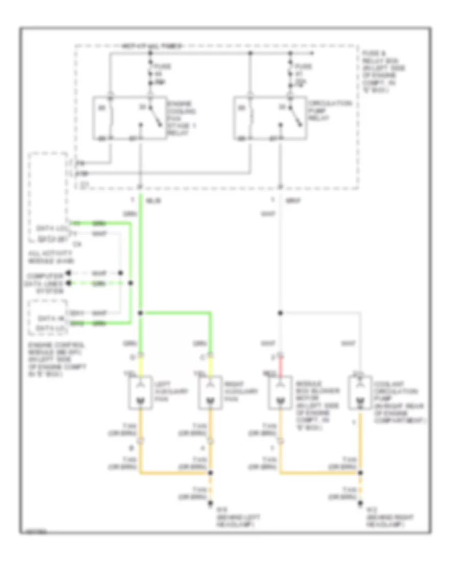
Cooling Fan Wiring Diagram for Mercedes-Benz ML320 2001
List of elements for Cooling Fan Wiring Diagram for Mercedes-Benz ML320 2001:
- All activity module (aam)
- Circulation pump relay
- Computer data lines system
- Coolant circulation pump (in right rear of engine compartment)
- D11
- D12
- Data hi
- Data lo
- Engine control module (me-sfi) (in left side of engine compt in "e" box)
- Engine cooling fan stage 1 relay
- Fuse & relay box (in left side of engine compt, in "e" box)
- Fuse 25a
- Fuse 30a
- Hot at all times
- Left auxiliary fan
- Ml/b
- Module box blower motor (in left side of engine compt, in "e" box)
- Mr/f
- Red
- Right auxiliary fan
- W2 (behind right headlamp)
- W9 (behind left headlamp)
CRUISE CONTROL
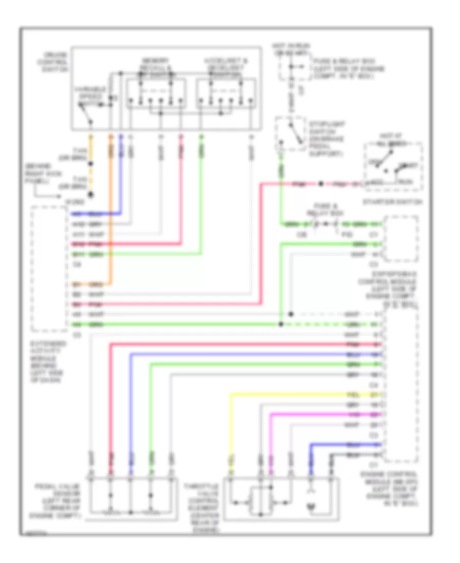
Cruise Control Wiring Diagram for Mercedes-Benz ML320 2001
List of elements for Cruise Control Wiring Diagram for Mercedes-Benz ML320 2001:
- (behind right kick panel)
- A11
- A12
- Acc
- Accel/set & decel/set switch
- B11
- B12
- C/e
- C/f
- Cruise control switch
- Engine control module (me-sfi) (left side of engine compt, in "e" box)
- Esp/sps/bas control module (left side of engine compt, in "e" box)
- Extended activity module (behind left side of dash)
- Fuse & relay box
- Fuse & relay box (left side of engine compt, in "e" box)
- Hot at all times
- Hot in run or start
- Memory recall & off switch
- Off
- P/d
- Pedal value sensor (left rear corner of engine compt)
- Pnk
- Run
- Start
- Starter switch
- Stoplight switch (on brake pedal support)
- Throttle valve control element (center rear of engine)
- Variable speed switch
- W29/2
DEFOGGERS
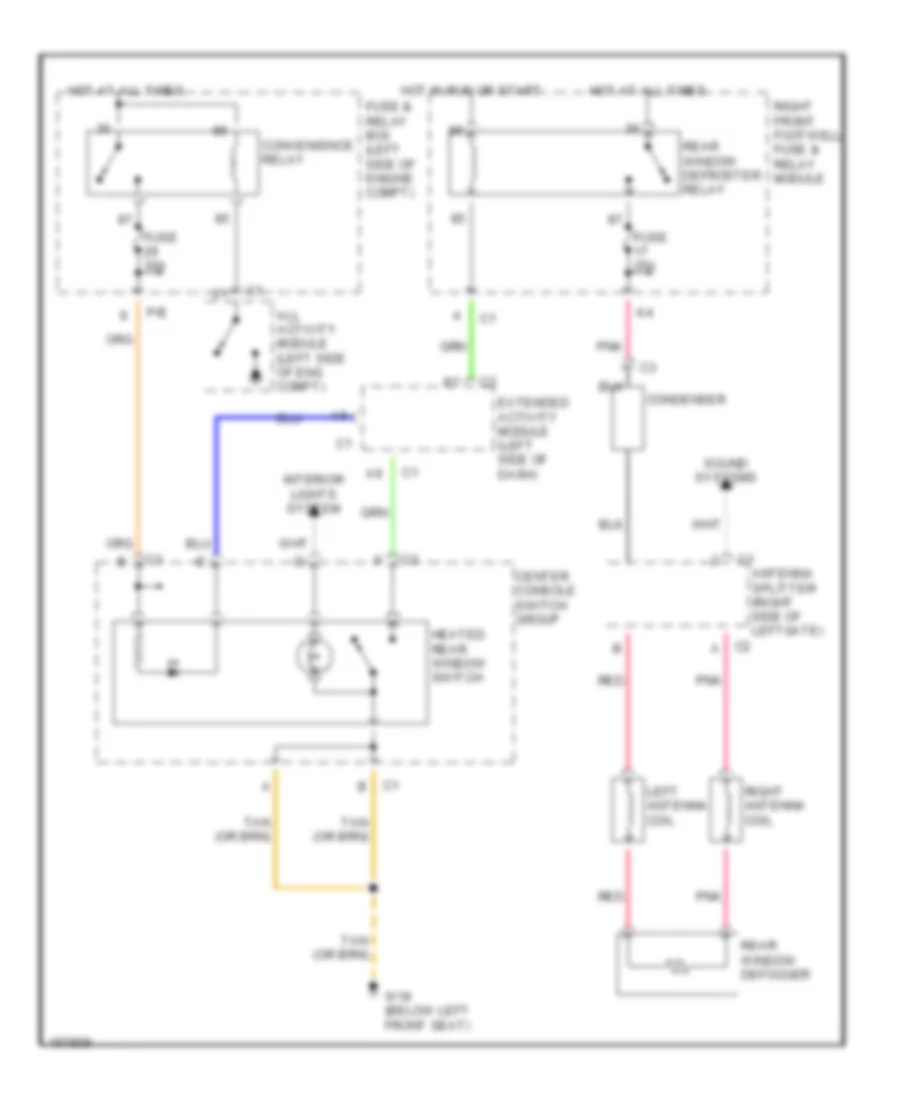
Defoggers Wiring Diagram for Mercedes-Benz ML320 2001
List of elements for Defoggers Wiring Diagram for Mercedes-Benz ML320 2001:
- All activity module (left side of eng compt)
- Antenna splitter (right side of leftgate)
- C2 a
- Center console switch group
- Condenser
- Convenience relay
- Extended activity module (left side of dash)
- Fuse & relay box (left side of engine compt)
- Fuse 25a
- Fuse 30a
- Heated rear window switch
- Hot at all times
- Hot in run or start
- Interior lights system
- Left antenna coil
- P/e
- Pnk
- Rear window defogger
- Rear window defroster relay
- Red
- Right antenna coil
- Right front footwell fuse & relay module
- Sound systems
- W18 (below left front seat)
ENGINE PERFORMANCE
3.2L
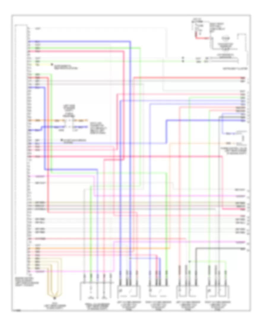
3.2L, Engine Performance Wiring Diagram (1 of 3) for Mercedes-Benz ML320 2001
List of elements for 3.2L, Engine Performance Wiring Diagram (1 of 3) for Mercedes-Benz ML320 2001:
- (left side of engine compt)
- A11
- B10
- C/f
- Data link connector (dtc readout) (below left side of dash)
- Engine control module (me-sfi) (left side of engine compt, in e box)
- Fuse & relay box
- Fuse 7.5a
- G104 (left rear corner of eng compt)
- Hot at all times
- Instrument cluster
- Left oxygen sensor 1 (before twc) (in exhaust pipe)
- Left oxygen sensor 2 (after twc) (in exhaust pipe)
- Low engine oil indicator
- Malfunction indicator
- Mr/e
- Nca
- Pedal value sensor (left rear corner of engine compt)
- Pnk
- Purge control valve (left rear corner of engine compt)
- Red
- Right front footwell fuse & relay box
- Right oxygen sensor 1 (before twc) (in exhaust pipe)
- Right oxygen sensor 2 (after twc) (in exhaust pipe)
- Starting/charging system
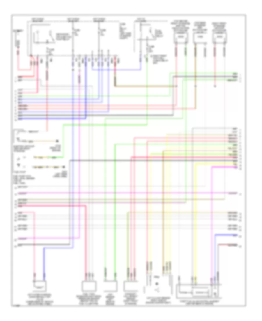
3.2L, Engine Performance Wiring Diagram (2 of 3) for Mercedes-Benz ML320 2001
List of elements for 3.2L, Engine Performance Wiring Diagram (2 of 3) for Mercedes-Benz ML320 2001:
- (right front of engine) air pump switchover valve
- (top center front of engine) shifting induction pipe switchover valve
- (top rear of engine) egr switchover valve
- Activated charcoal canister shut-off valve (under rear of vehicle, above spare wheel)
- Battery
- C/d
- Camshaft hall-effect sensor (right front of engine)
- Ckp sensor (left rear of engine)
- Electric air pump (center front of engine)
- Fuel pump
- Fuel pump relay
- Fuel pump with fuel level sensor (top of fuel tank)
- Fuel tank emissions monitoring pressure sensor (behind trim on fuel filler pipe)
- Fuse & relay box (left side of engine compt)
- Fuse 15a
- Fuse 20a
- Fuse 40a
- G125 (front of engine)
- G404 (left rear cargo area)
- Hot at all times
- Hot film maf sensor (right side of engine compartment)
- Hot in run or start
- M/a
- Mr/c
- Mr/d
- Mr/e
- P/d
- P/e
- Pnk
- Red
- Right front footwell fuse & relay box
- Secondary air injection pump relay
- Tan
- Throttle valve control element (center rear of engine)
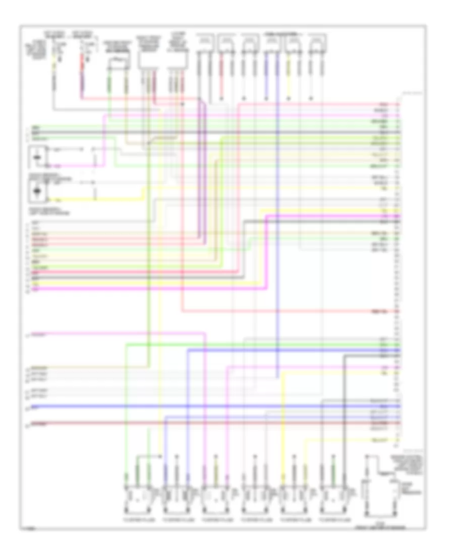
3.2L, Engine Performance Wiring Diagram (3 of 3) for Mercedes-Benz ML320 2001
List of elements for 3.2L, Engine Performance Wiring Diagram (3 of 3) for Mercedes-Benz ML320 2001:
- (center front of engine) ect sensor
- (lower right front of engine) oil sensor
- (right front of engine) pressure sensor
- Engine control module (me-sfi) (left side of engine compt, in e box)
- Fuel injectors
- Fuse & relay box (left side of engine compt)
- Fuse 15a
- G125 (front center of engine)
- Hot in run or start
- Ign coil
- Ign coil coil
- Knock sensor 1 (right side of engine)
- Knock sensor 2 (left side of engine)
- M/a
- M/c
- Noise sup- pressors
- Pnk
- Red
- Shield
- To spark plugs
EXTERIOR LIGHTS
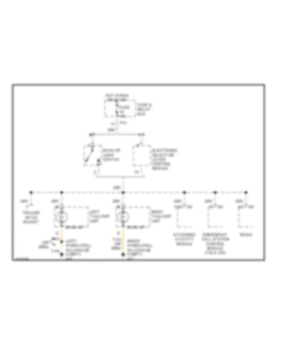
Back-up Lamps Wiring Diagram for Mercedes-Benz ML320 2001
List of elements for Back-up Lamps Wiring Diagram for Mercedes-Benz ML320 2001:
- (left wheelwell, in luggage compt) w6
- (right wheelwell, in luggage compt) w7
- A/t
- A10
- Back-up
- Back-up light switch
- Electronic selector lever control module
- Emergency call system control module (tele aid)
- Extended activity module
- Fuse & relay box
- Fuse 15a
- Hot in run or start
- Left taillight unit
- M/t
- P/c
- Radio
- Right taillight unit
- Tan
- Trailer hitch socket
Exterior Lights Wiring Diagram (1 of 2) for Mercedes-Benz ML320 2001
List of elements for Exterior Lights Wiring Diagram (1 of 2) for Mercedes-Benz ML320 2001:
- (behind right kick panel) w29/2
- 56a
- 56d
- 58l
- 58r
- 87a
- A11
- A13
- Accy
- All activity module
- All activity module (left side of engine compt)
- C/b
- C/d
- C/e
- Circuit relay
- Combination switch
- Flash
- From fuse 46 (diagram 2 of 2)
- Front & rear fog lamps switch
- Fuse & relay box (left side of engine compt)
- Fuse 7.5a
- Hazard flasher switch
- Head
- Headlamp flasher/ high beam switch
- Headlamp range adjustment control module
- Headlights system
- High
- Hot at all times
- Illum
- Instrument cluster
- Interior lights system
- Left license plate lamp
- Light switch
- Low
- Ml/a
- Mr/d
- Off
- P/b
- P/e
- P30
- Park
- Pnk
- Rear fog lamps on ind
- Red
- Right license plate lamp
- Run
- Shorting clip
- Standing
- Start
- Starter switch
- To left headlamp unit (diagram 2 of 2)
- To left taillamp unit (diagram 2 of 2)
- To right headlamp unit (diagram 2 of 2)
- To right taillamp unit (diagram 2 of 2)
- Turn signal switch
- W29/2 (behind right kick panel)
- W8 (center of tailgate)
Exterior Lights Wiring Diagram (2 of 2) for Mercedes-Benz ML320 2001
List of elements for Exterior Lights Wiring Diagram (2 of 2) for Mercedes-Benz ML320 2001:
- (left wheelwell, in luggage compt) w6
- (not used)
- (right wheelwell, in luggage compt) w7
- 87a
- A c1
- A10
- All activity module
- Back-up lights
- C/c
- C/d
- C/e
- C/f
- C/h
- Center high mounted stop lamp
- Circuit
- Circuit relay
- Electronic selctor lever control module
- Esp stoplight suppres- sion relay
- Esp/sps/bas control module
- F c2
- Fog
- From fuse 12 (diagram 1 of 2)
- From fuse 24 (diagram 1 of 2)
- Fuse & relay box (left side of engine compt)
- Fuse 10a
- Fuse 25a
- Fuse 7.5a
- Hot at all times
- Instrument cluster
- Left auxiliary turn signal lamp
- Left headlamp unit
- Left taillamp unit
- Left turn ind
- Left turn signal relay
- Ml/a
- Mr/d
- P/a
- P/c
- P/d
- P/e
- Pnk
- Rear fog lamp relay
- Red
- Right auxiliary turn signal lamp
- Right headlamp unit
- Right taillamp unit
- Right turn ind
- Right turn signal relay
- Sounder
- Standing/ parking
- Stop
- Stop lamp switch
- Tail/ parking
- Tan
- To combination switch (diagram 1 of 2)
- Trailer hitch socket
- Trailer turn signal control module
- Turn signal
- W/ door mounted spare wheel
- W/o door mounted spare wheel
- W2 (behind right headlamp)
- W29/2 (behind right kick panel)
- W6 (left wheelwell, in luggage compt)
- W8 (center of tailgate)
- W9 (behind left headlamp)
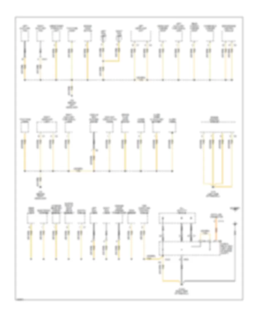
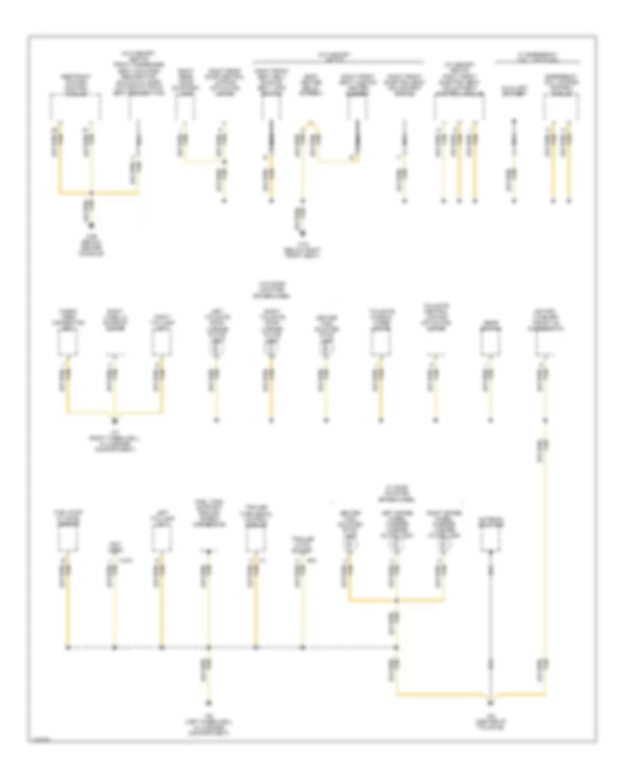
GROUND DISTRIBUTION
Ground Distribution Wiring Diagram (1 of 3) for Mercedes-Benz ML320 2001
List of elements for Ground Distribution Wiring Diagram (1 of 3) for Mercedes-Benz ML320 2001:
- Alarm horn
- Alarm siren w/ auxiliary battery
- All activity module
- Asr/ets/esp hydraulic unit
- Battery
- Brake fluid level switch
- C/b
- C/h
- Coolant circulation pump
- Data link connector
- Electronic compass
- Engine control module
- Engine hood switch
- Esp/sps/bas control module
- Fuse & relay box (left side of engine compt)
- Garage door opener transmitter
- Headlamp washer pump
- Interior rearview mirror assembly
- Left auxiliary fan
- Left auxiliary turn signal lamp
- Left fog lamp
- Left headlamp unit
- Left sun visor
- M4x1
- Module box blower motor
- Mr/d
- Nca
- Rain sensor
- Rear dome light
- Rear window washer pump
- Right auxiliary fan
- Right auxiliary turn signal lamp
- Right fog lamp
- Right headlamp unit
- Right sun visor
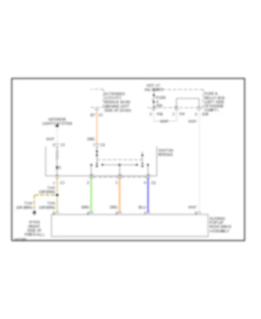
- Sliding/ pop-up roof drive assembly
- Switch module
- Tan
- Trip computer control module
- Two-tone horn
- W16 (left side of firewall)
- W16/4 (right side of firewall)
- W2 (behind right headlamp)
- W9 (behind left headlamp)
- Windshield washer pump
- Wiper motor
- X11/4
- X12/3
Ground Distribution Wiring Diagram (2 of 3) for Mercedes-Benz ML320 2001
List of elements for Ground Distribution Wiring Diagram (2 of 3) for Mercedes-Benz ML320 2001:
- (w/ memory seats) left front electric seat adjustment control module
- 87a
- A/c pushbutton control module
- A12
- Ata status indicator
- Audio amplifier
- C/f
- Center console switch group
- Combination switch
- Cruise control switch
- Data link connector
- Double combination switch
- Driver seat belt switch
- Electronic selector lever control module
- Esp off switch
- Etc control module
- Extended activity module (eam)
- Frequency switchover control module
- Front cigar lighter
- Front/rear fog lamp switch
- Fuse & relay box (left side of engine compt)
- Glove comp- artment lamp
- Headlamp cleaning system relay
- Headlamp cleaning system switch
- Headlamp range adjustment control module
- Heater/ a/c switch
- Horn/airbag clock spring contact
- Illum- ination
- In-car temperature sensor
- Instrument cluster
- Interior socket
- Kickdown switch
- Left electrically adjustable and heated outside rear- view mirror
- Left front door central locking actuating motor
- Left front door courtesy lamp
- Left front electric seat adjustment switch
- Left front seat cushion heater element
- Left front seat heater switch
- Left headlamp unit
- Left rear door central locking actuating motor
- Left rear door courtesy lamp
- Left rear power vent window switch
- Left rear seat belt/ comfort switch
- Low range switch
- Ml/c
- Mr/e
- Nca
- Outside mirror fold in/out switch
- Parking brake switch
- Radio
- Rear fog lamp indicator
- Rear window wiper/ washer switch
- Right electrically adjustable and heated outside rear- view mirror
- Right front door central locking actuating motor
- Right front door courtesy lamp
- Right front footwell fuse & relay module
- Right front seat heater switch
- Right headlamp unit
- Right rear power vent window switch
- Right rear seat belt/ comfort switch
- Seat heater relay (stage 1)
- Steering angle sensor
- Steering wheel
- Steering- lock switch
- Tan
- Temperature regulator microswitch
- Transfer case control module
- W/o memory seats
- W18 (below left front seat)
- W29/2 (behind right kick panel)
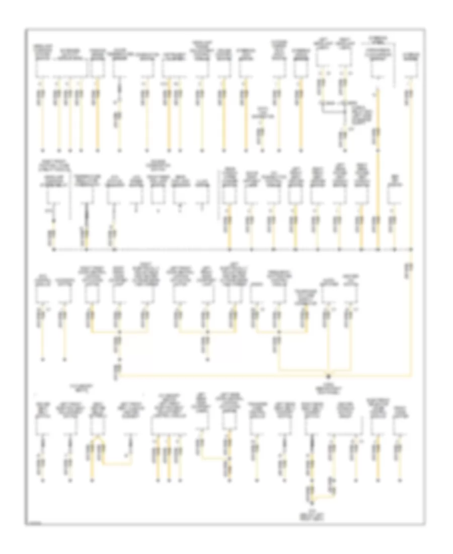
Ground Distribution Wiring Diagram (3 of 3) for Mercedes-Benz ML320 2001
List of elements for Ground Distribution Wiring Diagram (3 of 3) for Mercedes-Benz ML320 2001:
- (not used)
- (w/ memory seats) right front electric seat adjustment control module
- (w/o memory seats) front passenger seat occupied recognition switch w/ acsr (automatic child seat recognition)
- Antenna splitter
- Auxiliary battery
- Cargo area connector box
- Center high mounted stop lamp
- Emergency call system control module
- Fuel pump w/ level sensor
- Fuel tank support/ ground screw connection
- Left spare wheel carrier license plate lamp
- Left tailgate door license plate light
- Left taillamp unit
- Nca
- Rear switch
- Restraint system control module
- Right front electric seat adjustment switch
- Right front seat belt buckle/ belt lock switch
- Right front seat cushion heater element
- Right lamella sunroof motor
- Right rear door central locking actuating motor
- Right rear door courtesy lamp
- Right spare wheel carrier license plate lamp
- Right tailgate door license plate light
- Right taillamp unit
- Rotary tumbler/ trunk lid microswitch
- Seat heater relay (stage 1)
- Tailgate central locking actuating motor
- Tailgate window wiper motor
- Trailer hitch socket
- Trailer turn signal control module
- W/ door mounted spare wheel
- W/ emergency call (tele aid)
- W/o door mounted spare wheel
- W/o memory seats
- W19 (below right front seat)
- W26 (below center console)
- W6 (left wheelwell in luggage compartment)
- W7 (right wheelwell, in luggage compartment)
- W8 (center of tailgate)
- X18/3
- X58
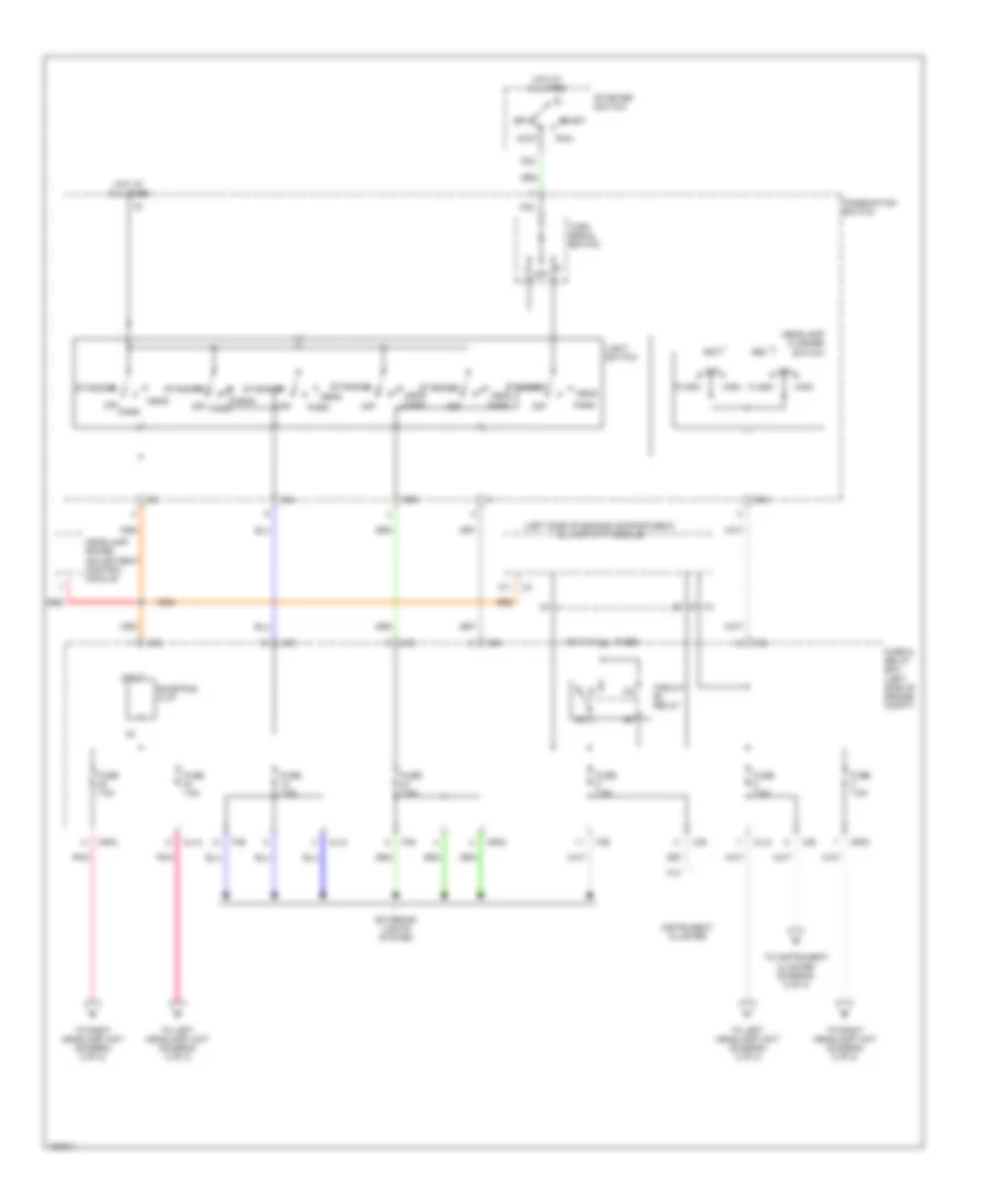
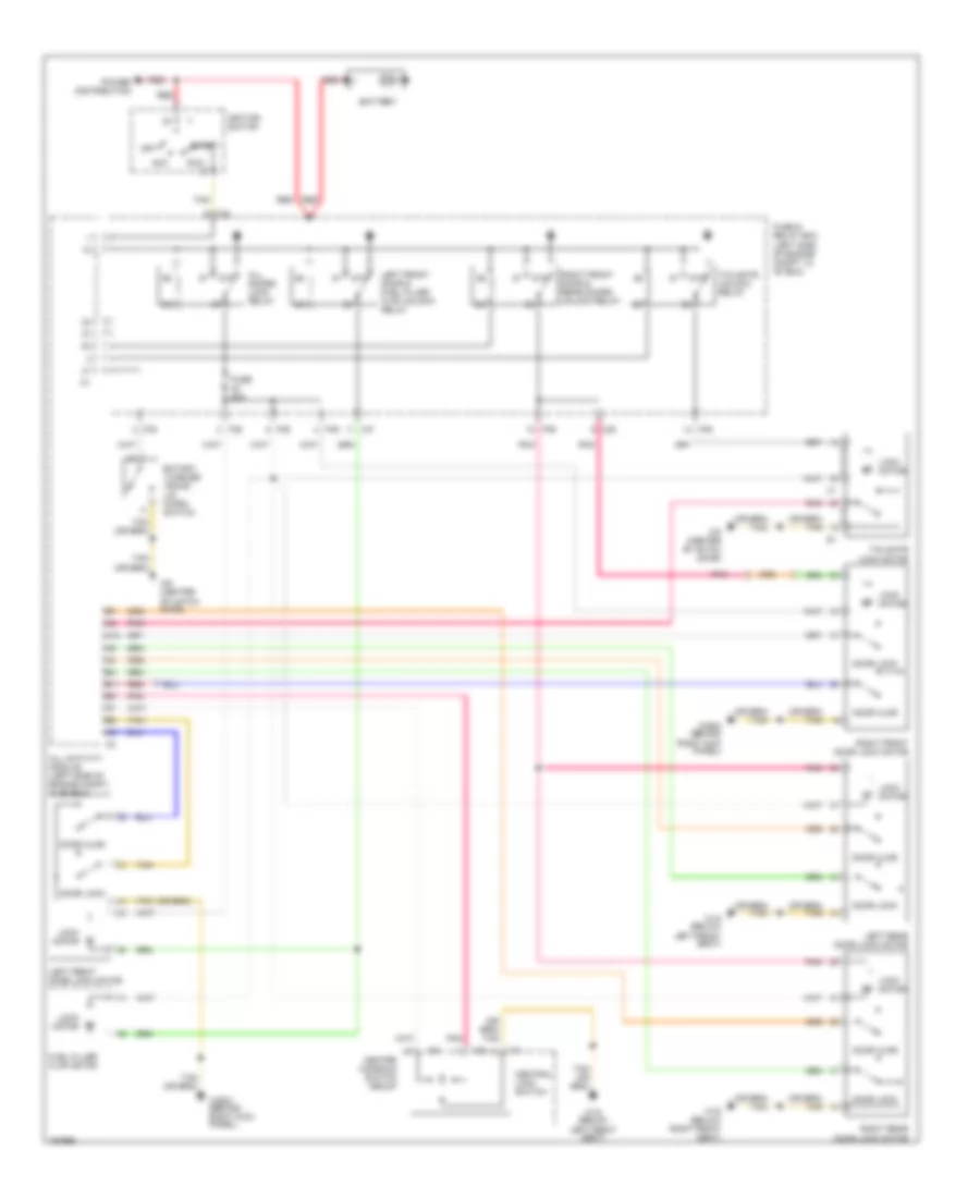
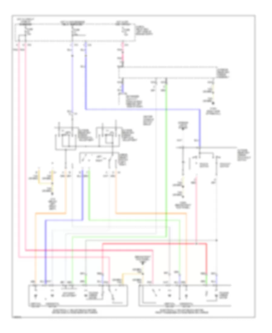
HEADLIGHTS
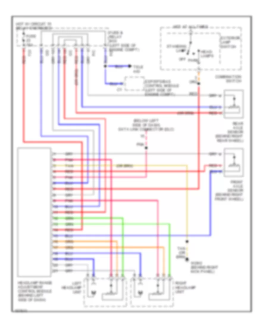
Headlamps Leveling Wiring Diagram for Mercedes-Benz ML320 2001
List of elements for Headlamps Leveling Wiring Diagram for Mercedes-Benz ML320 2001:
- (below left side of dash) data link connector (dlc)
- C/c red
- Combination switch
- Esp/sps/bas control module (left side of engine compt)
- Exterior lamp switch
- F23 red
- Front axle sensor (behind right front wheel)
- Fuse & relay box (left side of engine compt)
- Fuse 15a
- Head- lamps
- Headlamp range adjustment control module (behind left side of dash)
- Hot at all times
- Hot w/ circuit 15 relay energized
- Left headlamp unit
- Off park
- Pnk
- Rear axle sensor (behind right rear wheel)
- Red
- Right headlamp unit
- Standing lamp
- Tan
- Tele aid
- W29/2 (behind right kick panel)
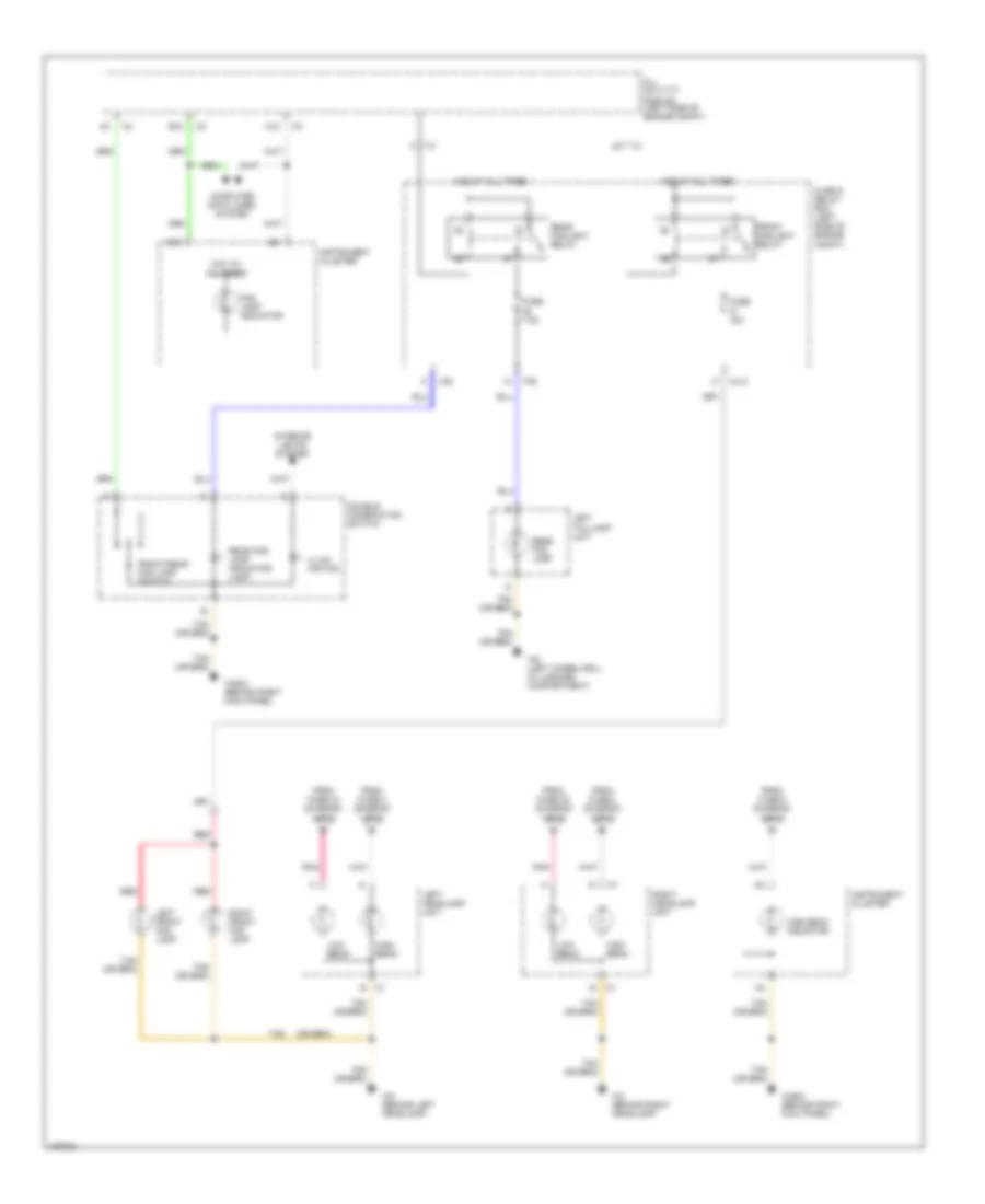
Headlights Wiring Diagram, with Xenon Lamps (1 of 2) for Mercedes-Benz ML320 2001
List of elements for Headlights Wiring Diagram, with Xenon Lamps (1 of 2) for Mercedes-Benz ML320 2001:
- (left side of engine compartment) all activity module
- 56a
- 56d
- 58l
- 58r
- 87a
- A11
- A13
- Accy
- C/b
- C/d
- C/e
- Circuit relay
- Combination switch
- Exterior lights system
- Flash
- Fuse & relay box (left side of engine compt)
- Fuse 7.5a
- Head
- Headlamp flasher switch
- Headlamp range adjustment control module
- High
- Hot at all times
- Instrument cluster
- Light switch
- Low
- Ml/a
- Mr/d
- Off
- P/b
- P/e
- P30
- Park
- Pnk
- Red
- Run
- Shorting clip
- Standing
- Start
- Starter switch
- To instrument cluster (diagram 2 of 2)
- To left headlamp unit (diagram 2 of 2)
- To right headlamp unit (diagram 2 of 2)
- Turn signal switch
Headlights Wiring Diagram, with Xenon Lamps (2 of 2) for Mercedes-Benz ML320 2001
List of elements for Headlights Wiring Diagram, with Xenon Lamps (2 of 2) for Mercedes-Benz ML320 2001:
- A12
- All activity module (left side of engine compt)
- B10
- B12
- C/e
- Computer data lines system
- Double combination switch
- Fog lamp indicator
- From fuse 3 (diagram 1 of 2)
- From fuse 34 (diagram 1 of 2)
- From fuse 35 (diagram 1 of 2)
- From fuse 5 (diagram 1 of 2)
- Front foglight relay
- Front/rear fog lamp switch
- Fuse & relay box (left side of engine compt)
- Fuse 15a
- Fuse 7.5a
- High beam
- High beam indicator
- Hot at all times
- Illum- ination
- Instrument cluster
- Interior lights system
- Left front fog lamp
- Left headlamp unit
- Left taillamp unit
- Low beam
- Ml/c
- P/e
- Pnk
- Rear fog lamp
- Rear fog lamp indicator lamp
- Rear foglight relay
- Red
- Right front fog lamp
- Right headlamp unit
- Tan
- W2 (behind right headlamp)
- W29/2 (behind right kick panel)
- W6 (left wheelwell in luggage compartment)
- W9 (behind left headlamp)
- Xenon headlamp control module
- Xenon headlamp ignition module
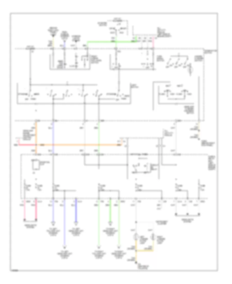
Headlights Wiring Diagram, without Xenon Lamps (1 of 2) for Mercedes-Benz ML320 2001
List of elements for Headlights Wiring Diagram, without Xenon Lamps (1 of 2) for Mercedes-Benz ML320 2001:
- (left side of engine compartment) all activity module
- 56a
- 56d
- 58l
- 58r
- 87a
- A11
- A13
- Accy
- C/b
- C/d
- C/e
- Circuit relay
- Combination switch
- Exterior lights system
- Flash
- Fuse & relay box (left side of engine compt)
- Fuse 7.5a
- Head
- Headlamp flasher switch
- Headlamp range adjustment control module
- High
- Hot at all times
- Instrument cluster
- Light switch
- Low
- Ml/a
- Mr/d
- Off
- P/b
- P/e
- P30
- Park
- Pnk
- Red
- Run
- Shorting clip
- Standing
- Start
- Starter switch
- To instrument cluster (diagram 2 of 2)
- To left headlamp unit (diagram 2 of 2)
- To right headlamp unit (diagram 2 of 2)
- Turn signal switch
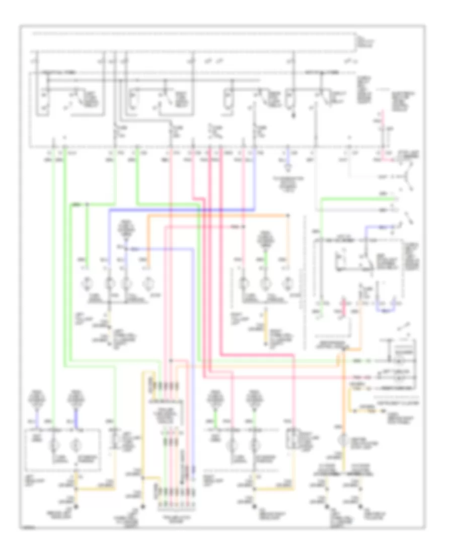
Headlights Wiring Diagram, without Xenon Lamps (2 of 2) for Mercedes-Benz ML320 2001
List of elements for Headlights Wiring Diagram, without Xenon Lamps (2 of 2) for Mercedes-Benz ML320 2001:
- A12
- All activity module (left side of engine compt)
- B10
- B12
- C/e
- Computer data lines system
- Double combination switch
- Fog lamp indicator
- From fuse 3 (diagram 1 of 2)
- From fuse 34 (diagram 1 of 2)
- From fuse 35 (diagram 1 of 2)
- From fuse 5 (diagram 1 of 2)
- Front foglight relay
- Front/rear fog lamp switch
- Fuse & relay box (left side of engine compt)
- Fuse 15a
- Fuse 7.5a
- High beam
- High beam indicator
- Hot at all times
- Illum- ination
- Instrument cluster
- Interior lights system
- Left front fog lamp
- Left headlamp unit
- Left taillamp unit
- Low beam
- Ml/c
- P/e
- Pnk
- Rear fog lamp
- Rear fog lamp indicator lamp
- Rear foglight relay
- Red
- Right front fog lamp
- Right headlamp unit
- Tan
- W2 (behind right headlamp)
- W29/2 (behind right kick panel)
- W6 (left wheelwell in luggage compartment)
- W9 (behind left headlamp)
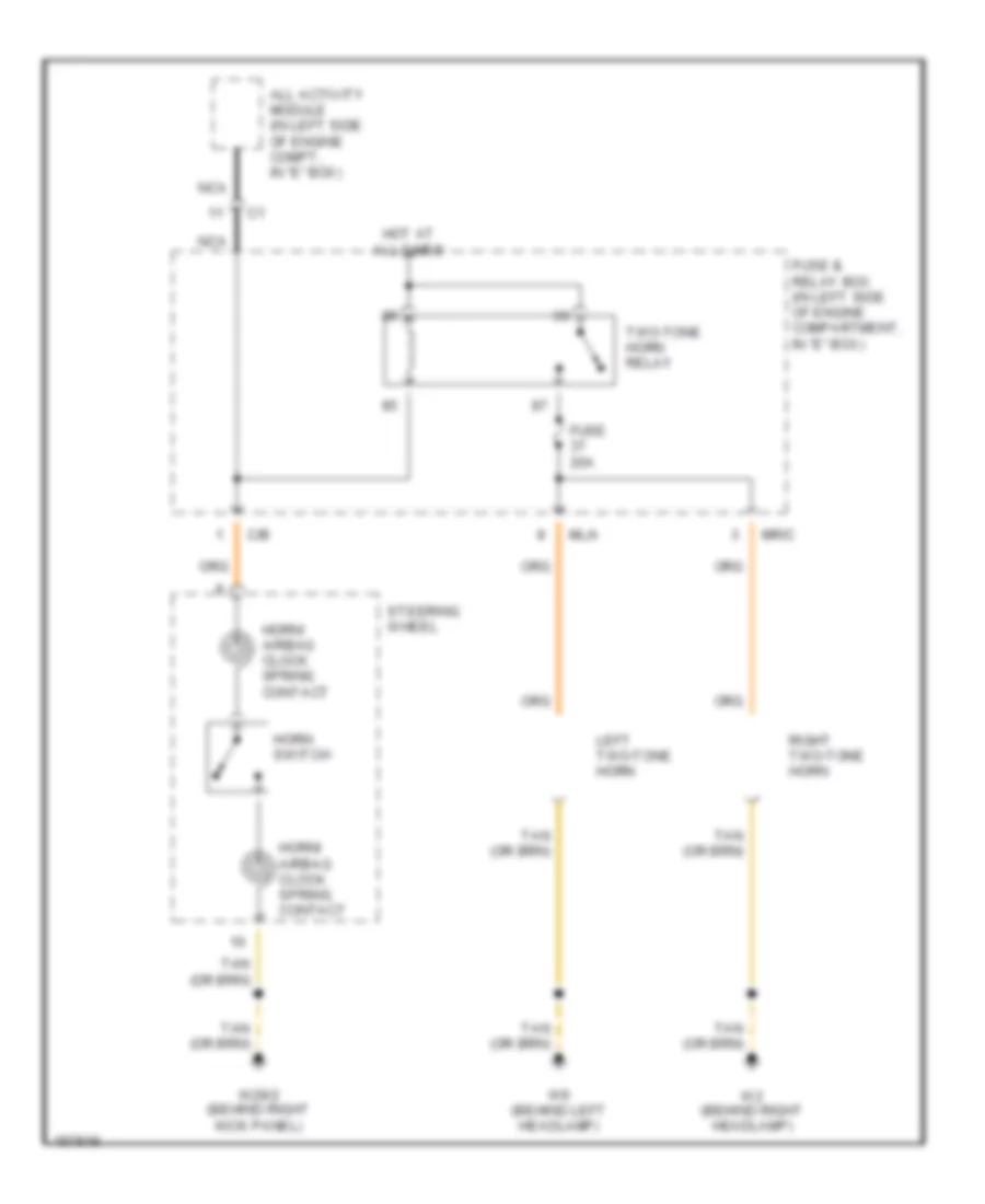
HORN
Horn Wiring Diagram for Mercedes-Benz ML320 2001
List of elements for Horn Wiring Diagram for Mercedes-Benz ML320 2001:
- All activity module (in left side of engine compt, in "e" box)
- C/b
- Fuse 20a
- Fuse & relay box (in left side of engine compartment, in "e" box)
- Horn switch
- Horn/ airbag clock spring contact
- Hot at all times
- Left two-tone horn
- Ml/a
- Mr/c
- Nca
- Right two-tone horn
- Steering wheel
- Two-tone horn relay
- W2 (behind right headlamp)
- W29/2 (behind right kick panel)
- W9 (behind left headlamp)
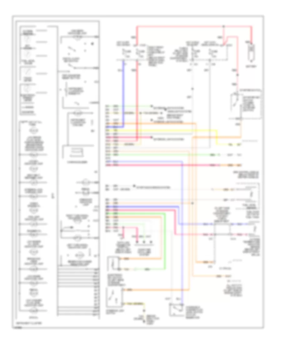
INSTRUMENT CLUSTER
Instrument Cluster Wiring Diagram for Mercedes-Benz ML320 2001
List of elements for Instrument Cluster Wiring Diagram for Mercedes-Benz ML320 2001:
- (behind right kick panel)
- (behind right kick panel) w29/2
- (in left side of engine compartment in "e" box) fuse & relay box
- 0 0 0 0
- 15c
- A10
- A11
- A12
- A13
- A14
- A15
- A16
- A17
- A18
- Abs mil
- Airbag off indicator lamp
- All activity module (aam) (in left side of engine compt, in "e" box)
- B10
- B11
- B12
- Bas/esp mil
- Battery
- Brake pad wear indicator lamp
- C/b
- C/c
- C/d
- C1 (pin 23)
- Check engine mil
- Computer data lines system
- Data link connector (partial) (below left side of dash)
- Digital clock set switch
- Ect gauge
- Electronic ecl switch (in left rear of engine compartment)
- Electronic speedo- meter
- Ets mil
- Exterior lights system
- Fog lamp indicator lamp
- Fuel level gauge
- Fuel level sensor
- Fuel pump (on top of fuel tank)
- Fuse & relay box (in left side of engine compartment, in "e" box)
- Fuse 15a
- Fuse 7.5a
- Generator charge indicator lamp
- Headlights system
- High beam indicator lamp
- Hot at all times
- Hot in off, acc or run
- Hot in run or start
- Hot with headlamps on
- Instrument cluster
- Instrument illumination (3 bulbs)
- Instrument illumination rheostat
- Interior lights system
- Left turn signal indicator lamp
- Low brake fluid level/ parking brake/ brake-force proportioning indicator lamp
- Low ecl indicator lamp
- Low engine oil level indicator lamp
- Low range indicator lamp
- Low washer fluid level indicator lamp
- M29/2
- Ml/a
- Odometer
- Outside temp ind
- Outside temperature indicator sensor (behind left side of front grille)
- Pnk
- Red
- Right front footwell fuse & relay box (below right side of dash, behind kick panel)
- Right turn signal indicator lamp
- Seat belt reminder lamp
- Srs control module (below front of center console)
- Srs mil
- Starter key switch (closed w/key in starter switch)
- Starter switch
- Starting/charging system
- Steering lock switch
- Steering lock warning lamp
- Tacho- meter
- Tan
- Trip odometer reset button
- Warning buzzer
- Windshield washer fluid level switch (in fluid reservoir)
- X12/3
- X12/9
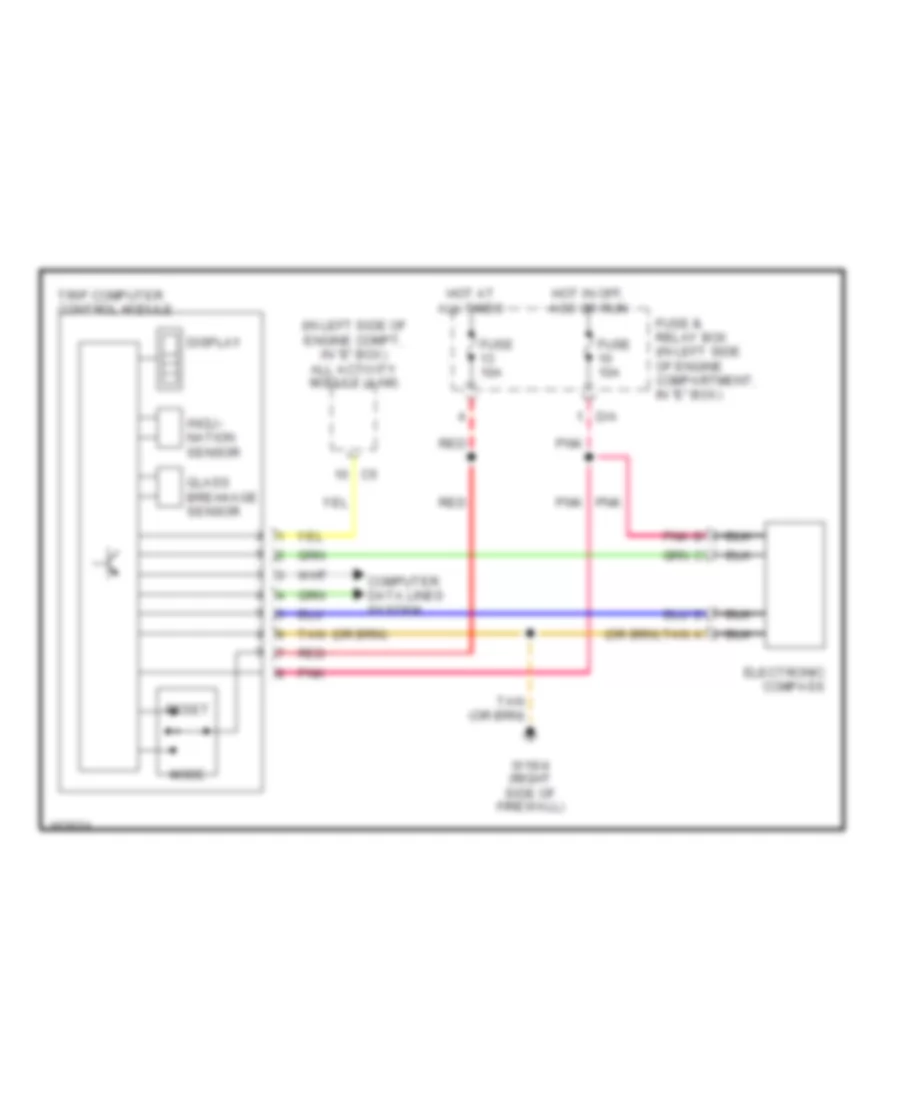
Trip Computer Wiring Diagram for Mercedes-Benz ML320 2001
List of elements for Trip Computer Wiring Diagram for Mercedes-Benz ML320 2001:
- (in left side of engine compt, in "e" box) all activity module (aam)
- Computer data lines system
- D/a
- Display
- Electronic compass
- Fuse & relay box (in left side of engine compartment, in "e" box)
- Fuse 10a
- Glass breakage sensor
- Hot at all times
- Hot in off, acc or run
- Incli- nation sensor
- Mode
- Pnk
- Pnk b
- Red
- Reset
- Tan
- Tan a
- Trip computer control module
- W16/4 (right side of firewall)
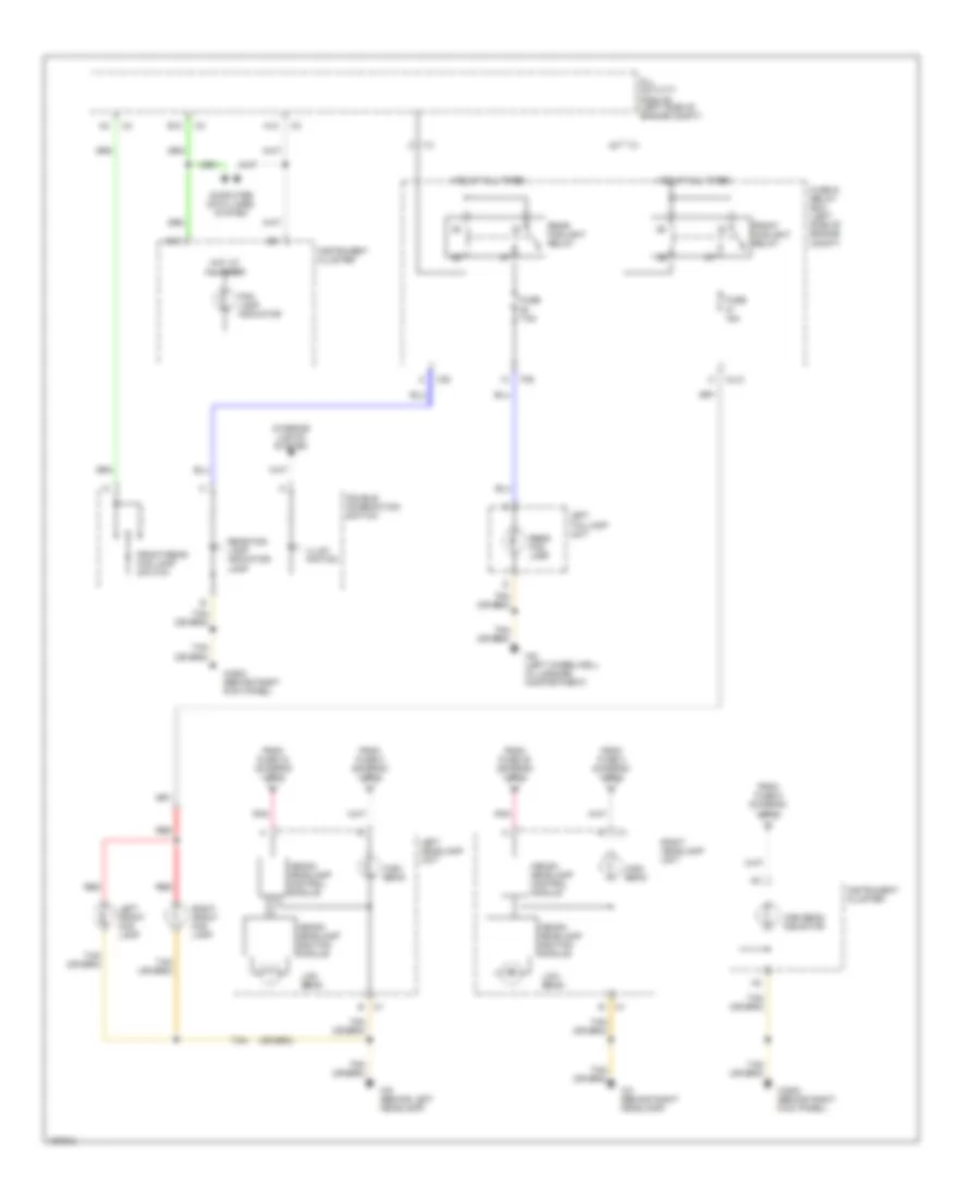
INTERIOR LIGHTS
Courtesy Lamps Wiring Diagram (1 of 2) for Mercedes-Benz ML320 2001
List of elements for Courtesy Lamps Wiring Diagram (1 of 2) for Mercedes-Benz ML320 2001:
- All activity module (aam) (in left side of engine compt, in "e" box)
- B11
- C/c
- D/a
- D/b
- Front dome lamp (with shut-off delay & front reading lamp)
- Fuse & relay box
- Fuse & relay box (in left side of engine compt, in "e" box)
- Fuse 10a
- Hot at all times
- Left front door central locking actuating motor
- Left front footwell illumination lamp
- Left rear dome lamp
- Left rear door central locking actuating motor
- P/d
- P/f
- Pnk
- Rear dome lamp
- Red
- Right front door central locking actuating motor
- Right front footwell illumination lamp
- Right rear dome lamp
- Right rear door central locking actuating motor
- Rotary tumbler micro- switch
- Rotary tumbler/ trunk lid micro- switch
- W16/4 (right side of firewall)
- W18 (below left front seat)
- W19 (below right front seat)
- W29/2 (behind right kick panel)
Courtesy Lamps Wiring Diagram (2 of 2) for Mercedes-Benz ML320 2001
List of elements for Courtesy Lamps Wiring Diagram (2 of 2) for Mercedes-Benz ML320 2001:
- B10
- B11
- B12
- C/b
- D/a
- Extended activity module (eam) (behind left side of dash)
- Fuse & relay box (in left side of engine compt, in "e" box)
- Fuse 10a
- Glove compartment lamp
- Hot in acc, run or start
- Left front door entrance/ exit lamp
- Left rear door entrance/ exit lamp
- Left sun visor (with illuminated vanity mirror)
- Nca
- Pnk
- Right front door entrance/ exit lamp
- Right rear door entrance/ exit lamp
- Right sun visor (with illuminated vanity mirror)
- W16/4 (right side of firewall)
- W18 (below left front seat)
- W19 (below right front seat)
- W29/2 (behind right kick panel)
Instrument Illumination Wiring Diagram for Mercedes-Benz ML320 2001
List of elements for Instrument Illumination Wiring Diagram for Mercedes-Benz ML320 2001:
- A11
- A13
- C/b
- C/e
- C1 a6
- C2 a
- C3 d
- Cargo area connector box
- Center console switch group
- Combination switch
- D/b
- Double combi- nation switch
- Electronic selector lever control module
- Esp off switch
- Exterior lamp switch
- Front cigar lighter
- Fuse & relay box (in left side of engine compt, in "e" box)
- Fuse 20a
- Fuse 7.5a
- Hcs switch (or headlamp range adjustment control module)
- Head
- Heater/ a/c switch
- Hot at all times
- Illum
- Illumination
- Instrument cluster
- Instrument illumination rheostat
- Left front seat heater switch
- Left rear power vent window switch
- Off
- Outside rearview mirror fold in/out switch
- P/c
- P/e
- Park
- Radio
- Rear window wiper/ washer switch
- Red
- Right front footwell fuse & relay box (below right side of dash, behind kick panel)
- Right front seat heater switch
- Right rear power vent window switch
- Solid state
- Standing
- Switch illumination
- Switch module
- Tan
- W16/4 (right side of firewall)
- W18 (below left front seat)
- W29/2 (behind right kick panel)
- W7 (right wheelwell, in luggage compartment)
MEMORY SYSTEMS
Driver"s Memory Seat Wiring Diagram for Mercedes-Benz ML320 2001
List of elements for Driver"s Memory Seat Wiring Diagram for Mercedes-Benz ML320 2001:
- (behind right kick panel) w29/2
- A10
- Aft
- Backrest aft
- Backrest fore
- Backrest fore/aft motor
- C10
- C11
- Extended activity module (behind left side of dash)
- Fore
- Fore/aft motor
- Front lower
- Front raise
- Front raise/ lower motor
- Fuse 20a
- Fuse 30a
- Hot w/ circuit 15 relay energized
- Hot w/ seat comfort relay energized
- Interior lights system
- Left front backrest heater element
- Left front electric seat adjustment control module (under left front seat)
- Left front electric seat adjustment switch
- Left front seat belt buckle/belt lock switch (in driver's seat belt buckle)
- Left front seat cushion heater element
- Left front seat heater switch
- Level 1 ind
- Level 2 ind
- Memory 1
- Memory 2
- Memory 3
- Memory store
- Nca
- Normal
- Pnk
- Rapid
- Rear lower
- Rear raise
- Rear raise/ lower motor
- Restraint system control module
- Right front footwell fuse & relay module
- Right front seat circuit
- Tan
- W18 (below left front seat)
Passenger"s Memory Seat Wiring Diagram for Mercedes-Benz ML320 2001
List of elements for Passenger"s Memory Seat Wiring Diagram for Mercedes-Benz ML320 2001:
- (behind right kick panel) w29/2
- Aft
- Backrest aft
- Backrest fore
- Backrest fore/aft motor
- C10
- C11
- Extended activity module (behind left side of dash)
- Fore
- Fore/aft motor
- Front lower
- Front passenger seat occupied recognition w/ automatic child seat recognition
- Front raise
- Front raise/ lower motor
- Fuse 20a
- Fuse 30a
- Hot w/ circuit 15 relay energized
- Hot w/ seat comfort relay energized
- Interior lights system
- Level 1 ind
- Level 2 ind
- Memory 1
- Memory 2
- Memory 3
- Memory store
- Nca
- Normal
- Pnk
- Rapid
- Rear lower
- Rear raise
- Rear raise/ lower motor
- Red
- Restraint system control module
- Right front backrest heater element
- Right front electric seat adjustment control module (under right front seat)
- Right front electric seat adjustment switch
- Right front footwell fuse & relay module
- Right front seat belt buckle/belt lock switch (in driver's seat belt buckle)
- Right front seat circuit
- Right front seat cushion heater element
- Right front seat heater switch
- Tan
- W19 (below right front seat)
POWER DISTRIBUTION
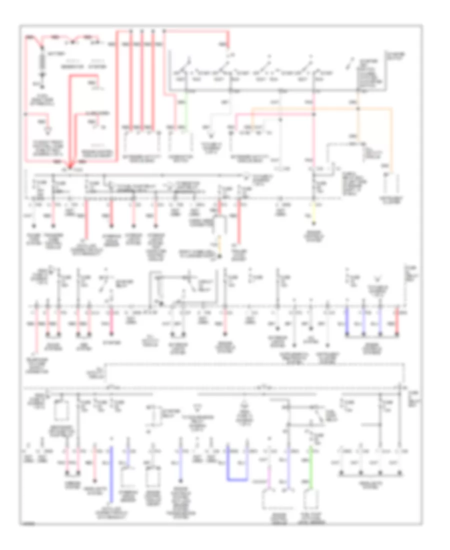
Power Distribution Wiring Diagram (1 of 4) for Mercedes-Benz ML320 2001
List of elements for Power Distribution Wiring Diagram (1 of 4) for Mercedes-Benz ML320 2001:
- (not used)
- (right wheelwell, in luggage compt) w7
- 15c
- 15r
- A/c system
- A10
- Abs system
- Accy
- Alarm siren
- All activity module
- Battery
- C/a
- C/b
- C/c
- C/d
- C/e
- C/f
- Cargo area connector
- Circuit relay
- Combination switch
- D/a
- Data link connector (dlc) (dtc readout)
- Engine control module
- Engine control module (me-sfi)
- Engine controls system
- Engine controls system, anti-lock brakes system, transmissions system
- Engine controls systems
- Extended activity module (eam)
- Exterior lights system
- F23
- From e fuse 18 (diagram 1 of 4)
- From f fuse 19 (diagram 1 of 4)
- From fuse 13 (diagram 1 of 4)
- Fuel pump relay
- Fuel pump with fuel level sensor
- Fuse
- Fuse & relay box
- Fuse & relay box (in left side of engine compt, in "e" box)
- Fuse 10a
- Fuse 15a
- Fuse 20a
- Fuse 25a
- Fuse 30a (or 40a)
- Fuse 40a
- Fuse 7.5a
- Generator
- Headlights system
- Instrument cluster
- Instrument cluster system
- Interior lights system
- Interior lights system, trip computer control module
- M/a
- M/c
- Mirrors system
- Ml/a
- Mr/a
- Mr/b
- Mr/c
- Mr/d
- Mr/e
- Off
- P/a
- P/b
- P/c
- P/d
- P/e
- P30
- Pnk
- Power tops system
- Red
- Run
- Secondary air injection pump relay
- Sound systems
- Start
- Starter
- Starter key switch (closed with key in starter switch)
- Starter relay
- Starter switch
- Steering angle sensor
- Tan
- To convenience relay (diagram 2 of 4)
- To fuel pump relay (diagram 1 of 4)
- To fuse 10 (diagram 2 of 4)
- To fuse 20 (diagram 1 of 4)
- To fuse 21 (diagram 1 of 4)
- To rear fog lamp relay (diagram 3 of 4)
- To right front footwell fuse & relay box (diagram 4 of 4)
- Trailer hitch socket
- Transfer case control module
- W16/4 (right side of firewall)
- X12/3
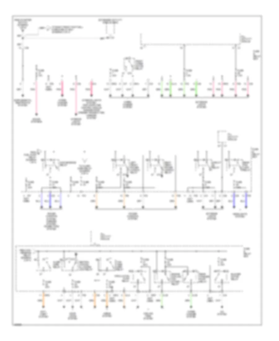
Power Distribution Wiring Diagram (2 of 4) for Mercedes-Benz ML320 2001
List of elements for Power Distribution Wiring Diagram (2 of 4) for Mercedes-Benz ML320 2001:
- (not used)
- 87a
- A/c system
- Alarm horn relay
- All activity module
- Anti- theft system
- B5 c3
- Blower motor relay
- C/b
- C/c
- C/d
- C/e
- C/f
- C/g
- Central locking, all doors lock relay
- Circuit relay
- Circulation pump relay
- Convenience relay
- Cooling fans system
- D/a
- Door locks system
- Engine cooling fan stage 1 relay
- Extended activity module (eam)
- Exterior lights system
- From con- venience i
- From g fuel pump relay (diagram 1 of 4)
- From starter switch (diagram 1 of 4)
- Front wiper motor relay
- Fuse
- Fuse & relay box
- Fuse 10a
- Fuse 15a
- Fuse 20a
- Fuse 25a
- Fuse 30a
- Fuse 7.5a
- Headlights system
- Horns system
- Interior lights system
- Interior lights system, trip computer control module, garage door opener transmitter, mirrors system
- Left front power window relay
- Ml/a
- Ml/b
- Mr/a
- Mr/c
- Mr/d
- Mr/f
- P/b
- P/c
- P/d
- P/e
- P/f
- Pnk
- Power windows system
- Power windows system, mirrors system, power tops system
- Rear fog lamp relay
- Rear washer pump relay
- Relay (diagram 2 of 4)
- Right front power window relay
- Sound systems
- To alarm horn relay (diagram 2 of 4)
- To right front footwell fuse & relay box (diagram 4 of 4)
- Two- tone horn relay
- Wiper/ washer system
Power Distribution Wiring Diagram (3 of 4) for Mercedes-Benz ML320 2001
List of elements for Power Distribution Wiring Diagram (3 of 4) for Mercedes-Benz ML320 2001:
- (not used)
- 87a
- Anti-lock brakes system
- Brake booster vacuum pump control module
- C/c
- C/d
- C/e
- C/f
- C/h
- Circuit 58l relay (drl only)
- Circuit 58r relay (drl only)
- Door locks system
- Engine control systems
- Esp/ stoplamp suppression relay
- Exterior lights system
- From fuse 13 (diagram 1 of 4)
- From left front door & fuel filler flap unlock relay (diagram 3 of 4)
- From right turn signal relay (diagram 3 of 4)
- Front fog lamp relay
- Front wiper motor relay
- Fuse & relay box
- Fuse & relay box (in left side of engine compt, in "e" box)
- Fuse 10a
- Fuse 15a
- Fuse 20a
- Fuse 40a
- Fuse 7.5a
- Headlights system
- High pressure/ return pump relay
- K10
- Left front door & fuel filler flap unlock relay
- Left turn signal relay
- Low beam headlamp relay
- M/a
- Ml/a
- Ml/b
- Ml/c
- Mr/d
- Nca
- P/b
- P/c
- P/e
- Pnk
- Red
- Right front door & rear doors unlock relay
- Right turn signal relay
- Secondary air injection pump relay
- Shorting clip
- Tailgate unlock relay
- To circuit 58l relay (diagram 3 of 4)
- To tailgate unlock relay (diagram 3 of 4)
- W/drl
- W/o drl
Power Distribution Wiring Diagram (4 of 4) for Mercedes-Benz ML320 2001
List of elements for Power Distribution Wiring Diagram (4 of 4) for Mercedes-Benz ML320 2001:
- (below right side of dash, behind kick panel) right front footwell fuse & relay box
- 87a
- A12 c4
- A8 c3
- All activity module
- Circuit relay
- Defogger system
- Extended activity module (eam)
- From battery a (diagram 1 of 4)
- From starter switch (diagram 2 of 4)
- Front cigar lighter
- Fuse 15a
- Fuse 20a
- Fuse 25a
- Fuse 30a
- Fuse 7.5a
- Fuse 70a
- Headlamp cleaning system relay
- Heater relay
- Instrument cluster system
- Interior lights system
- Interior socket
- Pnk
- Rear window defroster relay
- Red
- Right front footwell fuse & relay box (below right side of dash, behind kick panel)
- Seat comfort relay
- Seats system
- Tan
- W18 (below left front seat)
- W29/2 (behind right kick panel)
- Wiper/ washer system
- X12/6
- X12/7
- X12/9
POWER DOOR LOCKS
Power Door Locks Wiring Diagram for Mercedes-Benz ML320 2001
List of elements for Power Door Locks Wiring Diagram for Mercedes-Benz ML320 2001:
- 87a
- A10
- Acc
- All activity module (left side of engine compt, in "e" box)
- All doors lock relay
- B11
- Battery
- C/d
- C/e
- C/f
- Center console switch group
- Central lock switch
- Door ajar
- Door lock
- Fuel filler flap motor
- Fuse & relay box (left side of engine compt, in "e" box)
- Fuse 20a
- Ignition switch
- Left front door & fuel filler flap unlock relay
- Left front door lock motor
- Left front seat)
- Left rear door lock motor
- Lock motor
- Off
- P/d
- P/e
- Pnk
- Power distribution
- Red
- Right front door & rear doors unlock relay
- Right front door lock motor
- Right rear door lock motor
- Rotary tumbler trunk lid micro- switch
- Run
- Start
- Tailgate lock motor
- Tailgate unlock relay
- Tan
- W18 (below
- W18 (below left front seat)
- W19 (below right front seat)
- W29/2 (behind right kick panel)
- W8 (center of hatch door)
POWER MIRRORS
Power Mirrors Wiring Diagram for Mercedes-Benz ML320 2001
List of elements for Power Mirrors Wiring Diagram for Mercedes-Benz ML320 2001:
- (behind right kick panel) w29/2
- A c1
- C/d
- Center console switch group
- D/a
- Day/night adjustment
- Down
- Electrically adjustable & heated driver side outside rearview mirror
- Electrically adjustable & heated front passenger outside rearview mirror
- Extended activity module (eam) (behind left side of dash)
- Fold in switch
- Fold out switch
- Folding mirror motor
- Fuse & relay box (left side of engine compt)
- Fuse 10a
- Fuse 15a
- Horizontal motor
- Hot in off, accy or run
- Hot w/ circuit 15 relay energized
- Hot w/ convenience relay energized
- Interior lights system
- Interior rearview mirror assembly
- Left
- Mirror select switch (left/ right)
- Nca
- Outside rearview mirror fold in/out switch
- Outside rearview mirror horizontal adjustment
- Outside rearview mirror verticle adjustment
- P/c
- P/d
- Pnk
- Red
- Right
- Vertical motor
- W16/4 (right side of firewall)
- W18 (below left front seat)
- W29/2 (behind right kick panel)
POWER SEATS
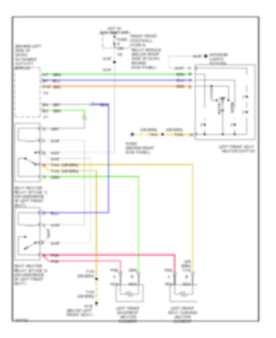
Driver Heated Seat Wiring Diagram for Mercedes-Benz ML320 2001
List of elements for Driver Heated Seat Wiring Diagram for Mercedes-Benz ML320 2001:
- (behind left side of dash) extended activity module
- A10
- Fuse 20a
- Hot in run or start
- Interior lights system
- Left front backrest heater element
- Left front seat cushion heater element
- Left front seat heater switch
- Nca
- Norm
- Off
- Pnk
- Rapid
- Relay module (below right side of dash, behind kick panel)
- Right front footwell fuse &
- Seat heater relay (stage 1) (on underside of left front seat)
- Seat heater relay (stage 2) (on underside of left front seat)
- Tan
- W18 (below left front seat)
- W29/2 (behind right kick panel)
Driver Power Seat Wiring Diagram for Mercedes-Benz ML320 2001
List of elements for Driver Power Seat Wiring Diagram for Mercedes-Benz ML320 2001:
- Aft
- Backrest
- Backrest fore/ aft motor
- Fore
- Front raise/ lower motor
- Front seat height
- Fuse 30a
- Hot in run or start
- Left front electric seat adjustment switch
- Lower
- Nca
- Pnk
- Raise
- Rear raise/ lower motor
- Rear seat height
- Relay module (below right side of dash, behind kick panel)
- Right front footwell fuse &
- S22x1
- Seat fore/ aft motor
- Seat fore/aft
- Tan
- W18 (below left front seat)
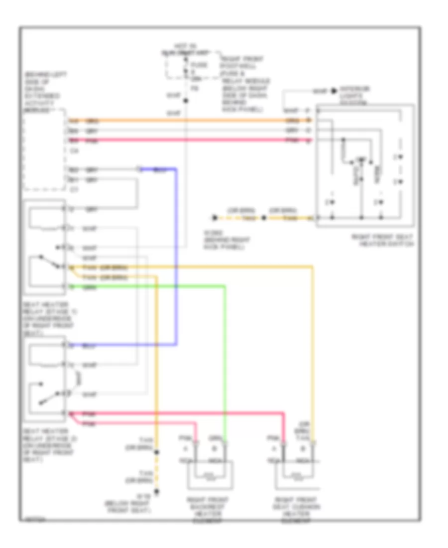
Passenger Heated Seat Wiring Diagram for Mercedes-Benz ML320 2001
List of elements for Passenger Heated Seat Wiring Diagram for Mercedes-Benz ML320 2001:
- (behind left side of dash) extended activity module
- Fuse 20a
- Hot in run or start
- Interior lights system
- Nca
- Norm
- Off
- Pnk
- Pnk e
- Rapid
- Relay module (below right side of dash, behind kick panel)
- Right front backrest heater element
- Right front footwell fuse &
- Right front seat cushion heater element
- Right front seat heater switch
- Seat heater relay (stage 1) (on underside of right front seat)
- Seat heater relay (stage 2) (on underside of right front seat)
- Tan
- W19 (below right front seat)
- W29/2 (behind right kick panel)
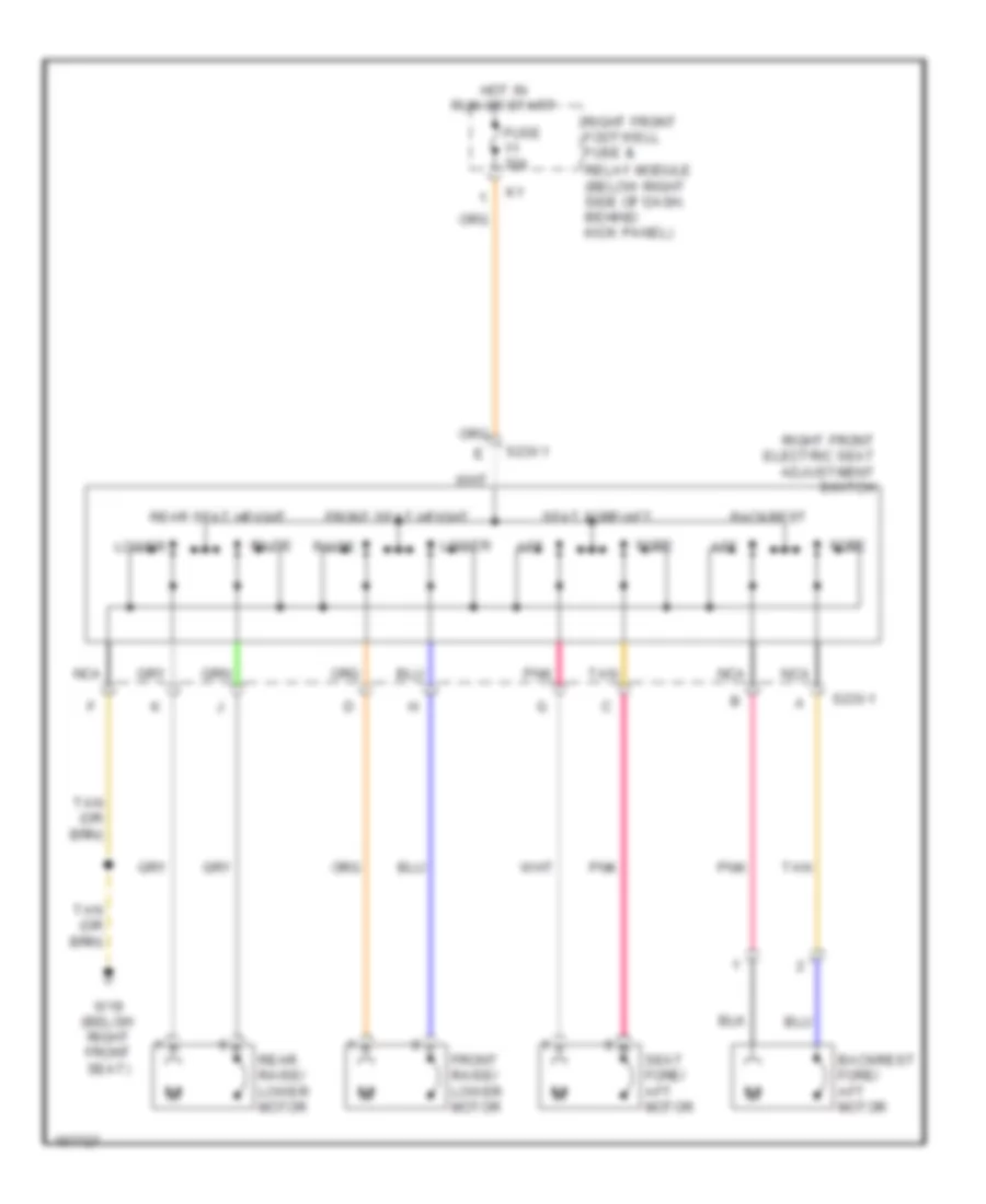
Passenger"s Power Seat Wiring Diagram for Mercedes-Benz ML320 2001
List of elements for Passenger"s Power Seat Wiring Diagram for Mercedes-Benz ML320 2001:
- Aft
- Backrest
- Backrest fore/ aft motor
- Fore
- Front raise/ lower motor
- Front seat height
- Fuse 30a
- Hot in run or start
- Lower
- Nca
- Pnk
- Raise
- Rear raise/ lower motor
- Rear seat height
- Relay module (below right side of dash, behind kick panel)
- Right front electric seat adjustment switch
- Right front footwell fuse &
- S23x1
- Seat fore/ aft motor
- Seat fore/aft
- Tan
- W19 (below right front seat)
POWER TOP/SUNROOF
Double Panel Sunroof Wiring Diagram for Mercedes-Benz ML320 2001
List of elements for Double Panel Sunroof Wiring Diagram for Mercedes-Benz ML320 2001:
- (right wheelwell, in luggage compt)
- C1 b7
- D/b
- Extended activity module (eam) (behind left side of dash)
- Fuse & relay box (left side of engine compt)
- Fuse 40a
- Hot at all times
- Interior lights system
- Left lamella sunroof motor
- Nca
- P/b
- P/f
- Right lamella sunroof motor
- Switch module
- Tan
- W16/4 (right side of firewall)
Single Panel Sunroof Wiring Diagram for Mercedes-Benz ML320 2001
List of elements for Single Panel Sunroof Wiring Diagram for Mercedes-Benz ML320 2001:
- C1 b7
- D/b
- Extended activity module (eam) (behind left side of dash)
- Fuse & relay box (left side of engine compt)
- Fuse 20a
- Hot at all times
- Interior lights system
- P/b
- P/f
- Sliding/ pop-up roof drive assembly
- Switch module
- W16/4 (right side of firewall)
POWER WINDOWS
Power Windows Wiring Diagram for Mercedes-Benz ML320 2001
List of elements for Power Windows Wiring Diagram for Mercedes-Benz ML320 2001:
- 0 off 1 close 2 open
- 0 off 1 close 2 open 3 exp down 4 lock 5 unlock
- 87a
- A11
- All activity module
- B10
- Center console switch group
- Convenience relay
- Fuse & relay box (left side of engine compt)
- Fuse 30a
- Hot at all times
- Left front power
- Left front power window motor
- Left front power window relay
- Left rear
- Left rear power window motor
- P/b
- P/d
- P/e
- Pnk
- Power window combination switch (rear center console)
- Power window switch
- Rear power windows safety switch
- Right front power
- Right front power window motor
- Right front power window relay
- Right rear
- Right rear power window motor
- W18 (below left front seat)
- Window switch
- X35/3
- X35/4
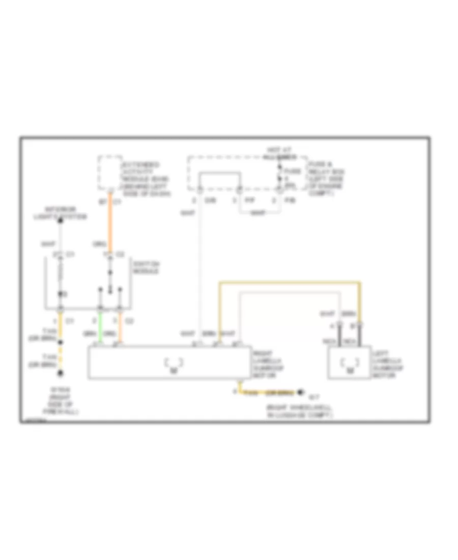
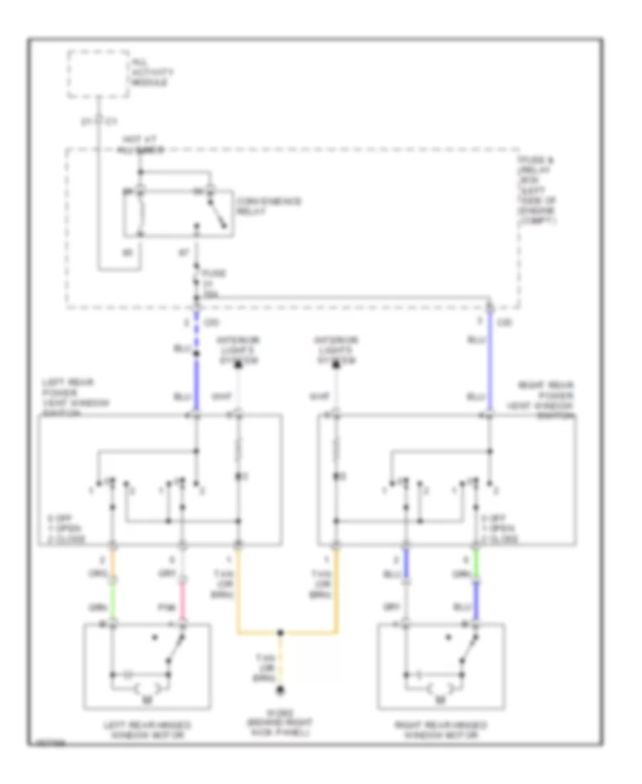
Rear Quarter Windows Wiring Diagram for Mercedes-Benz ML320 2001
List of elements for Rear Quarter Windows Wiring Diagram for Mercedes-Benz ML320 2001:
- 0 off 1 open 2 close
- All activity module
- C/d
- Convenience relay
- Fuse & relay box (left side of engine compt)
- Fuse 15a
- Hot at all times
- Interior lights system
- Left rear hinged window motor
- Left rear power vent window switch
- Pnk
- Right rear hinged window motor
- Right rear power vent window switch
- W29/2 (behind right kick panel)
RADIO
Base Radio Wiring Diagram, with Emergency Call System for Mercedes-Benz ML320 2001
List of elements for Base Radio Wiring Diagram, with Emergency Call System for Mercedes-Benz ML320 2001:
- (behind right kick panel)
- (below left side of dash) data link connector
- (center of tailgate) w8
- Antenna splitter (on right side of liftgate)
- Cd changer (in trunk)
- Coax
- Combination switch
- Defogger system
- Emergency call system control module
- Esp/sps/bas control module (left side of engine compt, in "e" box)
- Esp/sps/bas control module (under center console)
- Fm/am amplifier (in liftgate, behind trim)
- Fuse & relay box (left side of engine compt, in "e" box)
- Fuse 10a
- Fuse 25a
- Head
- Hot at all times
- Hot in off, acc or run
- Interior lights system
- Left antenna coil
- Left front door speaker
- Left rear door speaker
- Nca
- Off
- P/b
- P/d
- Park
- Pnk
- Pnk a
- Radio
- Rear window defroster element
- Red
- Red b
- Right antenna coil
- Right front door speaker
- Right rear door speaker
- Stand
- Tan
- W29/2
- X18
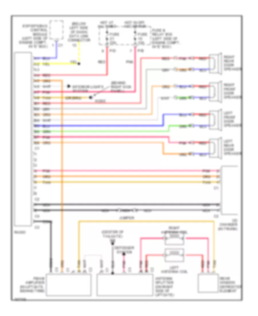
Base Radio Wiring Diagram, without Emergency Call System for Mercedes-Benz ML320 2001
List of elements for Base Radio Wiring Diagram, without Emergency Call System for Mercedes-Benz ML320 2001:
- (behind right kick panel)
- (below left side of dash) data link connector
- (center of tailgate) w8
- A pnk
- Antenna splitter (on right side of liftgate)
- Cd changer (in trunk)
- Coax
- Defogger system
- Esp/sps/bas control module (left side of engine compt, in "e" box)
- Fm/am amplifier (in liftgate, behind trim)
- Fuse & relay box (left side of engine compt, in "e" box)
- Fuse 10a
- Fuse 25a
- Hot at all times
- Hot in off, acc or run
- Interior lights system
- Jumper
- Left antenna coil
- Left front door speaker
- Left rear door speaker
- Nca
- P/b
- P/d
- Pnk
- Pnk a
- Radio
- Rear window defroster element
- Red
- Red b
- Right antenna coil
- Right front door speaker
- Right rear door speaker
- Tan
- W29/2
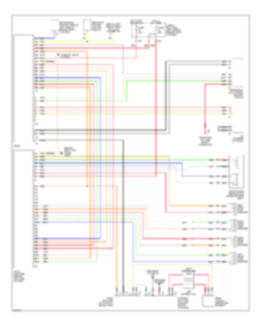
Premium Sound Radio Wiring Diagram, with Emergency Call System for Mercedes-Benz ML320 2001
List of elements for Premium Sound Radio Wiring Diagram, with Emergency Call System for Mercedes-Benz ML320 2001:
- (behind right kick panel) w29/2
- (below left side of dash) data link connector
- (center of tailgate) w8
- A10
- A11
- A12
- Acoustimass bass module (under driver's seat)
- Antenna splitter (on right side of liftgate)
- Audio amplifier (behind left side of dash)
- B10
- B11
- B12
- Cd changer (in trunk)
- Coax
- Defogger system
- Emergency call system control module
- Esp/sps/bas control module (left side of engine compt, in "e" box)
- Fm/am amplifier (in liftgate, behind trim)
- Fuse & relay box (left side of engine compt, in "e" box)
- Fuse 10a
- Fuse 25a
- Hot at all times
- Hot in off, acc or run
- Interior lights system
- Left antenna coil
- Left front door speaker
- Left rear door speaker
- Nca
- P/b
- P/d
- Pnk
- Pnk a
- Radio
- Rear window defroster element
- Red
- Red b
- Restraint system control module
- Right antenna coil
- Right front door speaker
- Right rear door speaker
- Tan
- X18
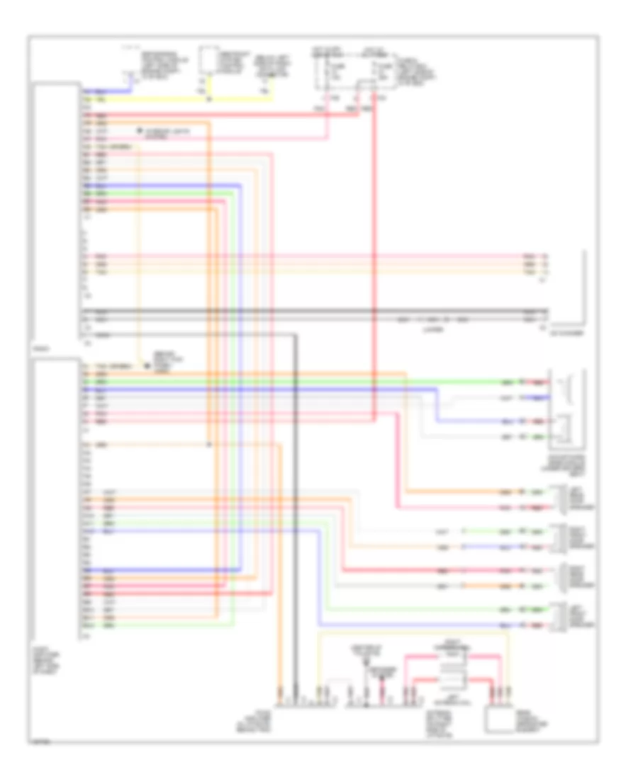
Premium Sound Radio Wiring Diagram, without Emergency Call System for Mercedes-Benz ML320 2001
List of elements for Premium Sound Radio Wiring Diagram, without Emergency Call System for Mercedes-Benz ML320 2001:
- (behind right kick panel) w29/2
- (below left side of dash) data link connector
- (center of tailgate) w8
- A10
- A11
- A12
- Acoustimass bass module (under driver's seat)
- Antenna splitter (on right side of liftgate)
- Audio amplifier (behind left side of dash)
- B10
- B11
- B12
- Cd changer
- Coax
- Defogger system
- Esp/sps/bas control module (left side of engine compt, in "e" box)
- Fm/am amplifier (in liftgate, behind trim)
- Fuse & relay box (left side of engine compt, in "e" box)
- Fuse 10a
- Fuse 25a
- Hot at all times
- Hot in off, acc or run
- Interior lights system
- Jumper
- Left antenna coil
- Left front door speaker
- Left rear door speaker
- Nca
- P/b
- P/d
- Pnk
- Pnk a
- Radio
- Rear window defroster element
- Red
- Red b
- Restraint system control module
- Right antenna coil
- Right front door speaker
- Right rear door speaker
- Tan
SHIFT INTERLOCK
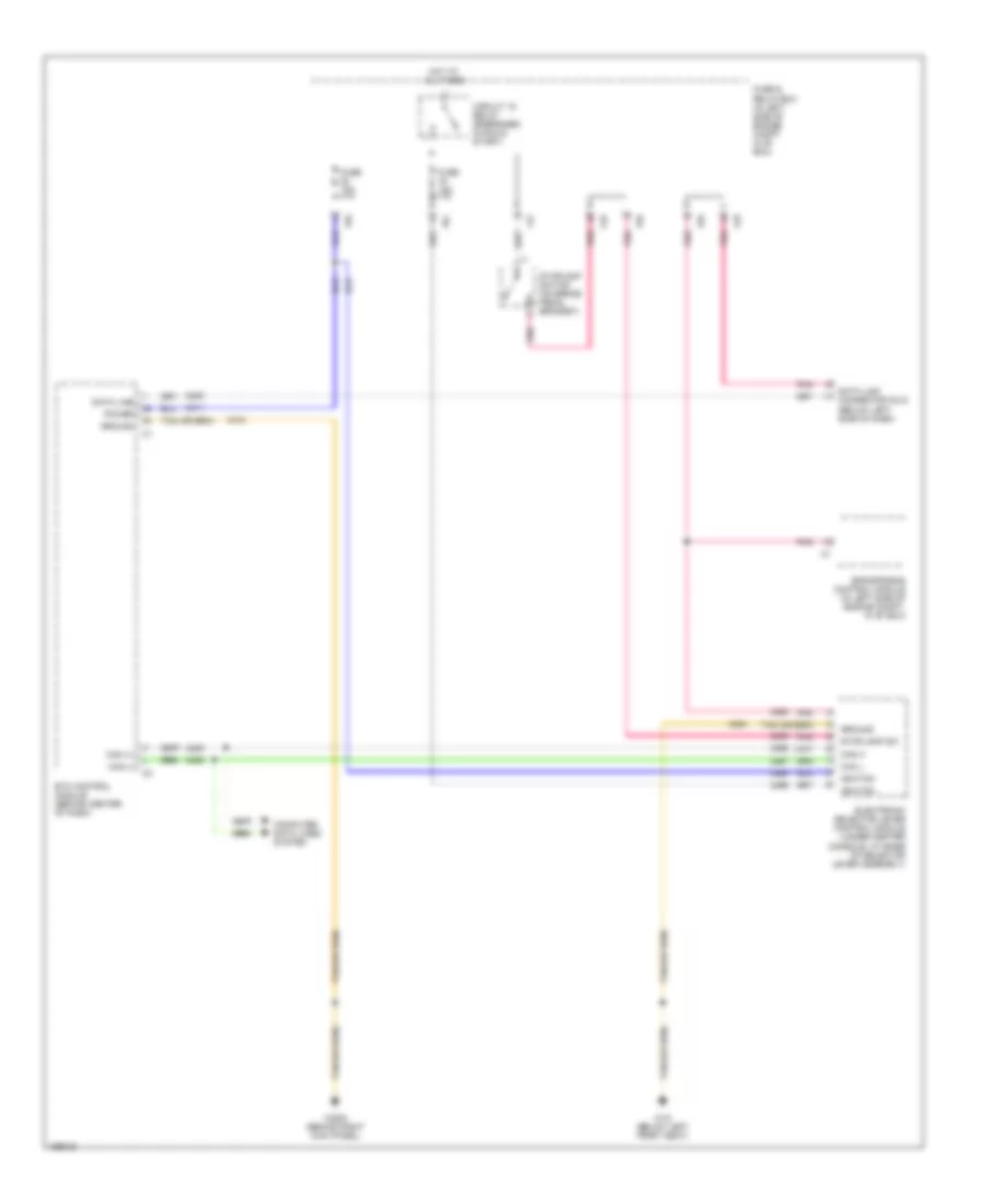
Shift Interlock Wiring Diagram for Mercedes-Benz ML320 2001
List of elements for Shift Interlock Wiring Diagram for Mercedes-Benz ML320 2001:
- C/b
- C/d
- C/f
- Can (+)
- Can (-)
- Can h
- Can l
- Circuit 15 relay (energized in run & start)
- Computer data lines system
- Data line
- Data link connector (dlc) (below left side of dash)
- Electronic selector lever control module (under center console, at base of selector lever assembly)
- Eps/sps/bas control module (in left side of engine compt, in "e" box)
- Etc control module (behind center of dash)
- Fuse & relay box (in left side of engine compt, in "e" box)
- Fuse 15a
- Ground
- Hot at all times
- Ignition
- P/c
- P/d
- Pnk
- Power
- Stoplamp sw
- Stoplamp switch (on brake pedal bracket)
- W18 (below left front seat)
- W29/2 (behind right kick panel)
STARTING/CHARGING
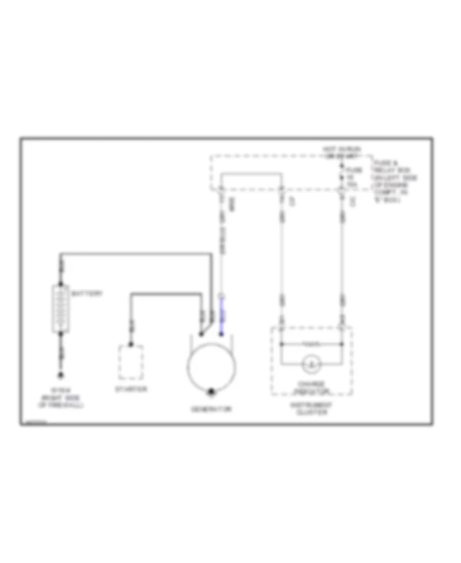
Charging Wiring Diagram for Mercedes-Benz ML320 2001
List of elements for Charging Wiring Diagram for Mercedes-Benz ML320 2001:
- Battery
- C/c
- C/f
- Charge indicator
- Fuse & relay box (in left side of engine compt, in "e" box)
- Fuse 15a
- Generator
- Hot in run or start
- Instrument cluster
- Mr/e
- Starter
- W16/4 (right side of firewall)
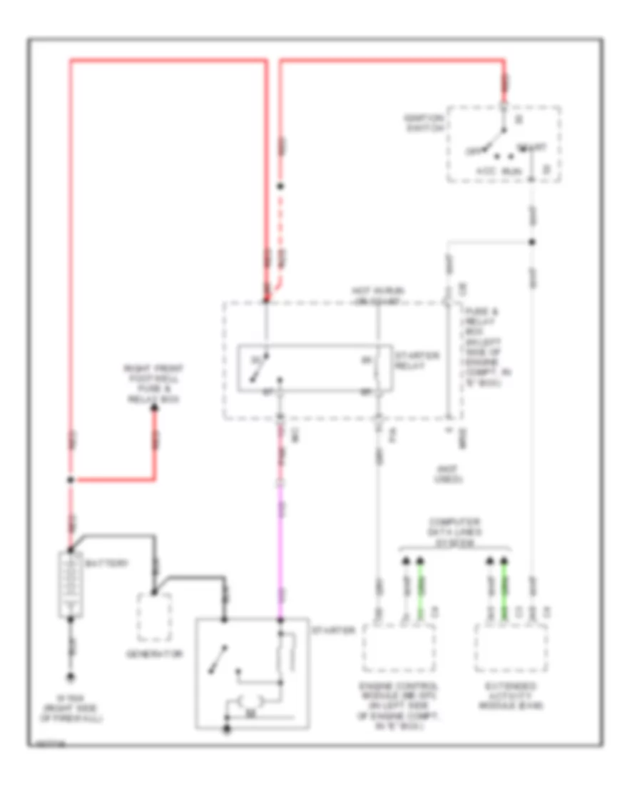
Starting Wiring Diagram for Mercedes-Benz ML320 2001
List of elements for Starting Wiring Diagram for Mercedes-Benz ML320 2001:
- (not used)
- Acc
- Battery
- C/e
- Computer data lines system
- Engine control module (me-sfi) (in left side of engine compt, in "e" box)
- Extended activity module (eam)
- Fuse & relay box (in left side of engine compt, in "e" box)
- Generator
- Hot in run or start
- Ignition switch
- M/c
- Mr/e
- Off
- P/a
- Pnk
- Red
- Right front footwell fuse & relay box
- Run
- Start
- Starter
- Starter relay
- W16/4 (right side of firewall)
SUPPLEMENTAL RESTRAINTS
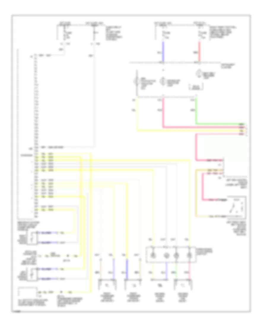
Supplemental Restraints Wiring Diagram, with Memory Seats (1 of 2) for Mercedes-Benz ML320 2001
List of elements for Supplemental Restraints Wiring Diagram, with Memory Seats (1 of 2) for Mercedes-Benz ML320 2001:
- (or 6106)
- 15r
- 2264 (or 3029)
- A11
- A15
- A18
- Air bag off indicator lamp
- All activity module (aam) (in left side of engine compartment in "e" box)
- Data link connector (dlc) (partial) (below left side of dash)
- Diagnosis
- Driver's air bag (a/b) squib 1
- Driver's air bag (a/b) squib 2
- Front passenger air bag (ab) squib 1
- Front passenger air bag (ab) squib 2
- Fuse & relay box (in left side of engine compartment, in "e" box)
- Fuse 15a
- Fuse 7.5a
- Horn/air bag clock spring contact
- Hot at all times
- Hot in off, acc or on
- Hot in on or start
- Instrument cluster
- Left door air bag squib
- Left esa control module (under left front seat)
- Left front seat belt buckle switch (in driver's seat belt buckle)
- Nca
- P/b
- P/c
- Pnk
- Red
- Restraint system control module (under center console)
- Right door air bag squib
- Right front footwell fuse & relay box (below right side of dash, behind kick panel)
- Seat belt reminder lamp
- Solid state
- Srs malfunction indicator lamp (mil)
- Tan
- Z51/14 (passenger harness, left side of engine compartment, in "e" box)
- Z51/16
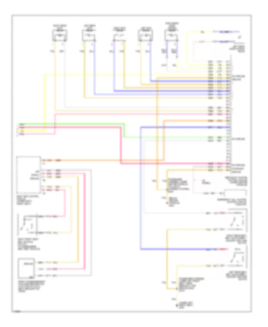
Supplemental Restraints Wiring Diagram, with Memory Seats (2 of 2) for Mercedes-Benz ML320 2001
List of elements for Supplemental Restraints Wiring Diagram, with Memory Seats (2 of 2) for Mercedes-Benz ML320 2001:
- (below center console) g302
- (passenger harness, under left front seat, near breakout for ground g300) z51/9
- (passenger tan harness, under center console in plastic harness channel) z53/9
- (under left front seat) g300
- 15r
- Diagnosis
- Emergency call system control module (tele aid)
- Front passenger seat occupied recognition w/automatic child seat recognition (ascr)
- Ground
- Left etr squib
- Left rear door air bag squib
- Left rear etr squib
- Left rear seat belt buckle/belt comfort feature switch
- Nca
- Pnk
- Restraint system control module (under center console)
- Right esa control module (under right front seat)
- Right etr squib
- Right front seat belt buckle switch (in passenger's seat belt buckle)
- Right rear door air bag squib
- Right rear etr squib
- Right rear seat belt buckle/belt comfort feature switch
- Signal
- Sw ground
- Tan
- Us models
Supplemental Restraints Wiring Diagram, without Memory Seats (1 of 2) for Mercedes-Benz ML320 2001
List of elements for Supplemental Restraints Wiring Diagram, without Memory Seats (1 of 2) for Mercedes-Benz ML320 2001:
- (partial) (below left side of dash)
- (passenger harness, under front of center console, near breakout for radio & srs control module) z52/15
- 15r
- 2395 (or 6106)
- A11
- A15
- A18
- Air bag off indicator lamp
- All activity module (aam) (in left side of engine compartment in "e" box)
- Data link connector (dlc)
- Diagnosis
- Driver's air bag (a/b) squib 1
- Driver's air bag (a/b) squib 2
- Front passenger air bag (ab) squib 1
- Front passenger air bag (ab) squib 2
- Fuse & relay box (in left side of engine compartment, in "e" box)
- Fuse 15a
- Fuse 7.5a
- Horn/air bag clock spring contact
- Hot at all times
- Hot in off, acc or on
- Hot in on or start
- Instrument cluster
- Left door air bag squib
- P/b
- P/c
- Pnk
- Red
- Restraint system control module (under center console)
- Right door air bag squib
- Right front footwell fuse & relay box (below right side of dash, behind kick panel)
- Seat belt reminder lamp
- Solid state
- Srs malfunction indicator lamp (mil)
- Z51/14 (passenger harness, left side of engine compartment, in "e" box)
- Z51/16
Supplemental Restraints Wiring Diagram, without Memory Seats (2 of 2) for Mercedes-Benz ML320 2001
List of elements for Supplemental Restraints Wiring Diagram, without Memory Seats (2 of 2) for Mercedes-Benz ML320 2001:
- (below center console) g302
- (passenger harness, under center console in plastic harness channel) z53/9
- (passenger harness, under left front seat, near breakout for ground g300) z51/9
- (passenger harness, under right front seat, near breakout for ground g301) z52/1
- (passenger tan harness, under center console in plastic harness channel) z53/9
- (under left front seat) g300
- (under right front seat) g301
- 15r
- Diagnosis
- Emergency call system control module (tele aid)
- Front passenger seat occupied recognition w/automatic child seat recognition (ascr)
- Ground
- Left etr squib
- Left front seat belt buckle switch (in driver's seat belt buckle)
- Left rear door air bag squib
- Left rear etr squib
- Left rear seat belt buckle/belt comfort feature switch
- Pnk
- Red
- Restraint system control module (under center console)
- Right etr squib
- Right front seat beat buckle switch (in passenger's seat belt buckle)
- Right rear door air bag squib
- Right rear etr squib
- Right rear seat belt buckle/belt comfort feature switch
- Signal
- Sw ground
- Tan
- Us models
TRANSMISSION
4WD Wiring Diagram for Mercedes-Benz ML320 2001
List of elements for 4WD Wiring Diagram for Mercedes-Benz ML320 2001:
- (behind right kick panel)
- A11
- B10
- Battery
- Can h
- Can l
- Computer data lines system
- Double combination switch
- Fuse & relay box (left side of engine compt)
- Fuse 15a
- Fuse 25a
- Fuse 7.5a
- Ground
- High/low
- Hot at all times
- Hot in run or start
- Ignition
- Illum
- Instrument cluster
- Interior lights system
- Low range
- Low range ind
- Low range switch
- Low/high
- Nca
- P/c
- P/d
- Pnk
- Position 1
- Position 2
- Position 3
- Position 4
- Red
- Return
- Right front footwell fuse & relay box (behind right kick panel)
- Tan
- Transfer case control module (behind shift assembly)
- Transfer case range selection motor (left rear of transfer case)
- W18 (below left front seat)
- W29/2
A/T Wiring Diagram for Mercedes-Benz ML320 2001
List of elements for A/T Wiring Diagram for Mercedes-Benz ML320 2001:
- 1-2/ 4-5 valve
- 1-2/4-5 vlv
- 2-3 shift valve
- 2-3 vlv
- 3-4 shift valve
- 3-4 vlv
- Backup sw out
- C/b
- C/d
- C/f
- Can (+)
- Can (-)
- Can h
- Can l
- Circuit 15 relay (energized in run & start)
- Computer data lines system
- Data line
- Data link connector (below left side of dash)
- Electronic selector lever control module (base of gear selector lever)
- Eps/sps/bas control module (left side of engine compt, in "e" box)
- Etc control module (behind center of dash)
- Exterior lights system
- Fuse & relay box (left side of engine compt)
- Fuse 15a
- Ground
- Hot at all times
- Ignition
- Illum
- Interior lights
- Kickdown sw
- Kickdown switch (2001 ml320, 2001-02 ml430-ml500) (top of accelerator pedal)
- Lock up valve
- Modul- ator valve
- Modulator vlv
- Nca
- P/c
- P/d
- Pnk
- Power
- Pwm vlv
- Rpm 2
- Rpm 3
- Rpm sensor
- Sensor ground
- Sensor v+
- Shift valve
- Shift vlv
- Start interlock switch
- Stoplamp sw
- Stoplamp switch (on brake pedal bracket)
- Tan
- Temp sensor
- Temp/start
- Valve unit (electronic transmission control)
- W18 (below left front seat)
- W29/2 (behind right kick panel)
WIPER/WASHER
Front Wiper/Washer Wiring Diagram for Mercedes-Benz ML320 2001
List of elements for Front Wiper/Washer Wiring Diagram for Mercedes-Benz ML320 2001:
- (right side of firewall)
- 87a
- A12
- Acc
- All activity module (left side of engine compt)
- B12
- Battery
- C/b
- C/d
- C/f
- Can h
- Can l
- Combination switch
- Computer data lines system
- Extended activity module (eam) (behind left side of dash)
- Front wiper motor relay
- Fuse & relay box (left side of engine compt, in "e" box)
- Fuse 15a
- Fuse 30a
- Ground
- Hot in off, acc or run
- Hot in run or start
- Ignition
- Ignition switch
- Int
- Ml/a
- Mr/a
- Mr/d
- Mr/e
- Off
- P/d
- Power distribution
- Rain sensor
- Red
- Run
- Start
- Tan
- W16/4
- W16/4 (right side of firewall)
- W9 (behind left headlamp)
- Wash
- Washer switch
- Windshield washer pump
- Windshield wiper motor
- Wipe
- Wiper switch
Headlamp Washer Wiring Diagram for Mercedes-Benz ML320 2001
List of elements for Headlamp Washer Wiring Diagram for Mercedes-Benz ML320 2001:
- (behind right kick panel) w29/2
- Extended activity module (eam) (behind left side of dash)
- Fuse 30a
- Headlamp cleaning system relay
- Headlamp cleaning system switch
- Headlamp washer pump
- Hot at all times
- Interior lights system
- Right front footwell fuse & relay box (behind right kick panel)
- W9 (behind left headlamp)
Rear Wiper/Washer Wiring Diagram for Mercedes-Benz ML320 2001
List of elements for Rear Wiper/Washer Wiring Diagram for Mercedes-Benz ML320 2001:
- Acc
- All activity module (left side of engine compt)
- Battery
- C/c
- C/d
- Fuse & relay box (left side of engine compt, in "e" box)
- Fuse 15a
- Fuse 30a
- Hot in run or start
- Ignition switch
- Illum
- Interior lights system
- Ml/b
- Mr/d
- Off
- On ind
- Power distribution
- Rear window washer pump
- Rear window washer pump relay
- Rear window wiper/ washer switch
- Red
- Right front footwell fuse & relay module (behind right kick panel)
- Run
- Start
- Tailgate window wiper motor
- Tan
- W16/4 (right side of firewall)
- W29/2 (behind rick kick panel)
- W8 (center of tailgate)
- W9 (behind left headlamp)
- Wash

 Čeština
 Deutsch
 Ελληνικά
 English
 English
 Español
 Suomi
Suomi Français
 Français
 עברית
עברית Hrvatski
 Magyar
 Italiano
 日本語
日本語 한국어
한국어 Nederlands
 Polski
 Português
 Português
 Română
 Русский
 Slovenčina
 Slovenščina
 Svenska
 Türkçe
 中文 (中国)