ANTI-LOCK BRAKES
Anti-lock Brakes Wiring Diagram for Hyundai Elantra GT 2005
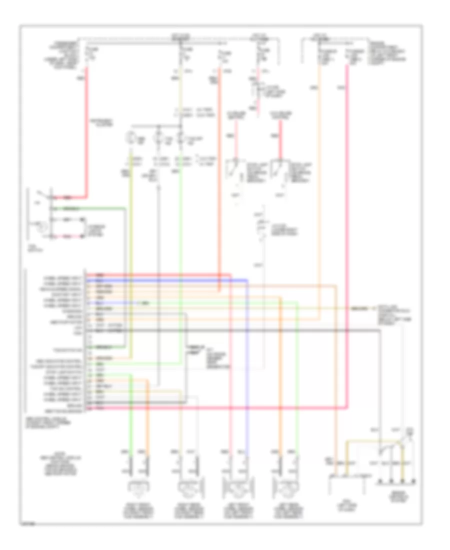
List of elements for Anti-lock Brakes Wiring Diagram for Hyundai Elantra GT 2005:
- (w/ trip)
- (w/o trip)
- (w/tcs)
- Abs control module (in right front corner of engine compt)
- Abs ind
- Abs indicator control
- Abs pump motor
- Abs/tcs solenoids
- C183-3
- Connector (dlc) (partial) (below left side of dash)
- Data link
- Diagnosis
- Engine compartment relay & fuse box (in left front corner of engine compt)
- Engine controls system
- Fuse 10a
- Fuse 15a
- Fusible link (abs 1) 30a
- Fusible link (abs 2) 30a
- G17 (on frame member, near generator)
- Ground
- High
- Hot at all times
- Hot in on or start
- I/p-b
- I/p-h
- I/p-j
- Illum
- Instrument cluster
- Interior lights system
- J/c c191 (lower right side of dash)
- J/c m36 (left side of dash)
- Left front wheel sensor (on left front hub assembly)
- Left rear wheel sensor (on left rear hub assembly)
- Low
- M09-1
- M09-2
- M09-3
- M10-1
- M10-2
- Nca
- Note: abs control module contains: abs solenoids, tcs solenoids & abs pump motor
- On/start input
- Passenger compartment junction block (under left side of dash, near kick panel)
- Pcm (left side of dash)
- Pnk
- Red
- Right front wheel sensor (on right front hub assembly)
- Right rear wheel sensor (on right rear hub assembly)
- Stop lamp switch
- Stop lamp switch (on brake pedal bracket)
- Tcs ind
- Tcs ind control
- Tcs off ind
- Tcs off indicator control
- Tcs switch
- Tcs switch on
- Vehicle speed signal
- W/ cruise control
- W/ trip
- W/o cruise control
- W/o tcs
- W/o trip
- Wheel speed input
 Čeština
 Dansk
Dansk Ελληνικά
 English
 English
 Español
 Suomi
Suomi Français
 Français
 עברית
עברית Hrvatski
 Magyar
 Italiano
 日本語
日本語 한국어
한국어 Nederlands
 Polski
 Português
 Português
 Română
 Русский
 Slovenčina
 Slovenščina
 Svenska
 Türkçe
 中文 (中国)
 Deutsch