STARTING/CHARGING
Charging Wiring Diagram for Hyundai Elantra GLS 1997
 https://portal-diagnostov.com/license.html
Automotive Electricians Portal FZCO
Automotive Electricians Portal FZCO
https://portal-diagnostov.com/license.html
https://portal-diagnostov.com/license.html
Automotive Electricians Portal FZCO
Automotive Electricians Portal FZCO
List of elements for Charging Wiring Diagram for Hyundai Elantra GLS 1997:
- (gl)
- (gls)
- (right front corner of engine compt) engine compartment fuse/relay box
- Battery
- Battery ground
- Charge warning indicator
- Dash fuse box (left kick panel)
- E31-1
- E31-2
- Electronic time & alarm control module (under center of dash, below radio)
- Fuse 10 10a
- Fuse 9 10a
- Generator
- Generator relay
- Hot in on or start
- I01-1
- I01-3
- I04-2
- I04-3
- Indicators
- Instrument cluster
- M38-3
- Red
- Starting system (start motor)
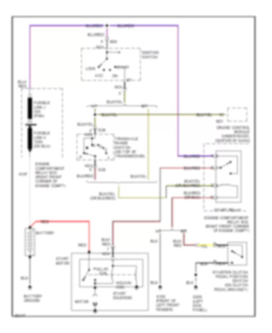
Starting Wiring Diagram for Hyundai Elantra GLS 1997
List of elements for Starting Wiring Diagram for Hyundai Elantra GLS 1997:
- A/t
- Acc
- Battery
- Battery ground
- Cruise control module (under radio, center of dash)
- E28
- Engine compartment relay box (right front corner of engine compt)
- Fusible link j 30a (pnk)
- G100 (front of left front fender)
- G200 (left kick panel)
- Hold-in coil
- Ignition switch
- Lock
- M/t
- M21
- M24
- Motor
- N d
- Nca
- Pull-in coil
- Red
- Start
- Start motor
- Start relay
- Start solenoid
- Starter clutch pedal position switch (on clutch pedal bracket)
- Transaxle range switch (on top of transmission)

 Čeština
 Dansk
Dansk Ελληνικά
 English
 English
 Español
 Suomi
Suomi Français
 Français
 עברית
עברית Hrvatski
 Magyar
 Italiano
 日本語
日本語 한국어
한국어 Nederlands
 Polski
 Português
 Português
 Română
 Русский
 Slovenčina
 Slovenščina
 Svenska
 Türkçe
 中文 (中国)