
 Čeština
 Dansk
Dansk Ελληνικά
 English
 English
 Español
 Suomi
Suomi Français
 Français
 עברית
עברית Hrvatski
 Magyar
 Italiano
 日本語
日本語 한국어
한국어 Nederlands
 Polski
 Português
 Português
 Română
 Русский
 Slovenčina
 Slovenščina
 Svenska
 Türkçe
 中文 (中国)

SUPPLEMENTAL RESTRAINTS
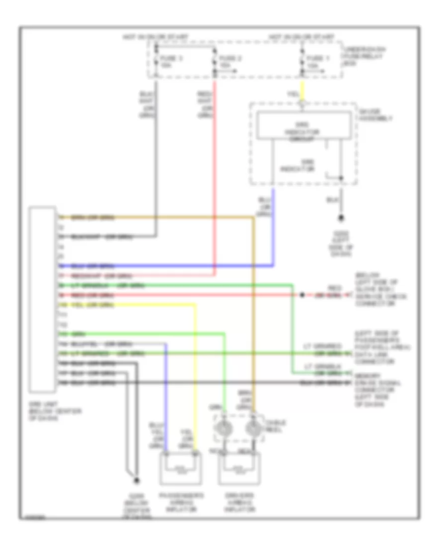
Supplemental Restraint Wiring Diagram for Isuzu Oasis S 1998
List of elements for Supplemental Restraint Wiring Diagram for Isuzu Oasis S 1998:

ANTI-LOCK BRAKESAIR CONDITIONINGANTI-THEFTBODY COMPUTERCOOLING FANCRUISE CONTROLCOMPUTER DATA LINESDEFOGGERSEXTERIOR LIGHTSENGINE PERFORMANCEHEADLIGHTSHORNGROUND DISTRIBUTIONINSTRUMENT CLUSTERINTERIOR LIGHTSPOWER DISTRIBUTIONPOWER DOOR LOCKSPOWER WINDOWSPOWER MIRRORSSUPPLEMENTAL RESTRAINTSSHIFT INTERLOCKSPOWER TOP/SUNROOFRADIOSTARTING/CHARGINGWARNING SYSTEMSTRANSMISSIONWIPER/WASHER