ANTI-LOCK BRAKES
Anti-lock Brake Wiring Diagrams (1 of 2) for Isuzu Oasis S 1998

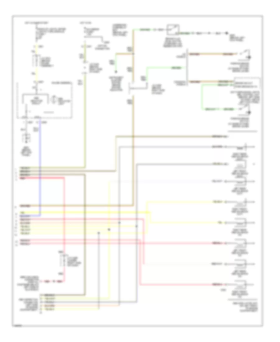
List of elements for Anti-lock Brake Wiring Diagrams (1 of 2) for Isuzu Oasis S 1998:
- (not used)
- 4
- Abs b1 fuse 43 20a
- Abs control unit (behind right kick panel)
- Abs fail-safe ctrl
- Abs fail-safe relay (behind left side of dash, right of steering column)
- Abs ind ctrl
- Abs modulator unit (on left front of engine compart- ment)
- Abs motor fuse 41 30a
- Abs pmp mtr ctrl
- Abs pump motor
- Abs pump motor relay
- Abs pump mtr in
- Abs unit fuse 42 7.5a
- Box)
- Brake pedal input
- Brake switch (behind dash, on brake pedal support)
- Brake/park input
- C259
- C260
- C262
- C265
- C353
- C401
- C464
- C465
- Data link connector (dlc) (partial) (on left side of front passenger's footwell area)
- Dlc input/output
- Early production 1998
- G100 (left front corner of engine compartment)
- G201 (behind right side of glove box)
- G203 (behind right kick panel)
- Ground
- Hot at all times
- Ignition
- J/c c423 (behind left side of dash)
- Late production 1998,
- Left front wheel sensor (inside wheel)
- Left rear wheel sensor (inside wheel)
- Lf abs sol ctrl
- Lf spd sens input
- Lr abs sol ctrl
- Lr spd sens input
- Radio cigar lighter fuse 36 15a
- Red
- Rf abs sol ctrl
- Rf spd sens input
- Right front wheel sensor (inside wheel)
- Right rear wheel sensor (inside wheel)
- Rr abs sol ctrl
- Rr spd sens input
- Sdl connector (partial) (behind left side of glove
- Serv chk conn in
- Stoplight horn fuse 30 15a
- Underdash fuse/relay box (behind left kick panel)
- Underhood abs fuse/relay box (on right rear of engine compartment)
- Underhood fuse/relay box (on right rear corner of engine compartment)
Anti-lock Brake Wiring Diagrams (2 of 2) for Isuzu Oasis S 1998
List of elements for Anti-lock Brake Wiring Diagrams (2 of 2) for Isuzu Oasis S 1998:
- (option connector)
- Abs indicator circuit
- Abs indicator light
- Abs inspection connector (left side of engine compartment)
- Abs modulator unit (on left front of engine compartment)
- Back-up lights, meter lights (turn signals) fuse 1 10a
- Brake fluid level switch (in brake fluid reservoir cap)
- Brake ind out
- C352
- C401
- C601
- C607
- C609
- C909
- Canadian models
- D10
- Daytime running lights (drl) control unit (behind left side of dash, above left kick panel)
- G200 (behind left kick panel)
- Gauge assembly
- Hot in on
- Hot in on or start
- Instrument cluster system (brake system indicator)
- J/c c445 (behind right side of dash)
- J/c c468 (behind right side of dash)
- J/c c469 (under right side of dash)
- J/c c610 (behind gauge assembly)
- Left front abs solenoid (in)
- Left front abs solenoid (out)
- Left rear abs solenoid (in)
- Left rear abs solenoid (out)
- Park brake sw in
- Parking brake switch (at base of park brake lever)
- R/c mirror fuse 7 7.5a
- Red
- Right front abs solenoid (in)
- Right front abs solenoid (out)
- Right rear abs solenoid (in)
- Right rear abs solenoid (out)
- Service check connector (partial) (fastened below left side of glove box)
- Underdash fuse/relay box (behind left kick panel)
- Us models