TRANSMISSION
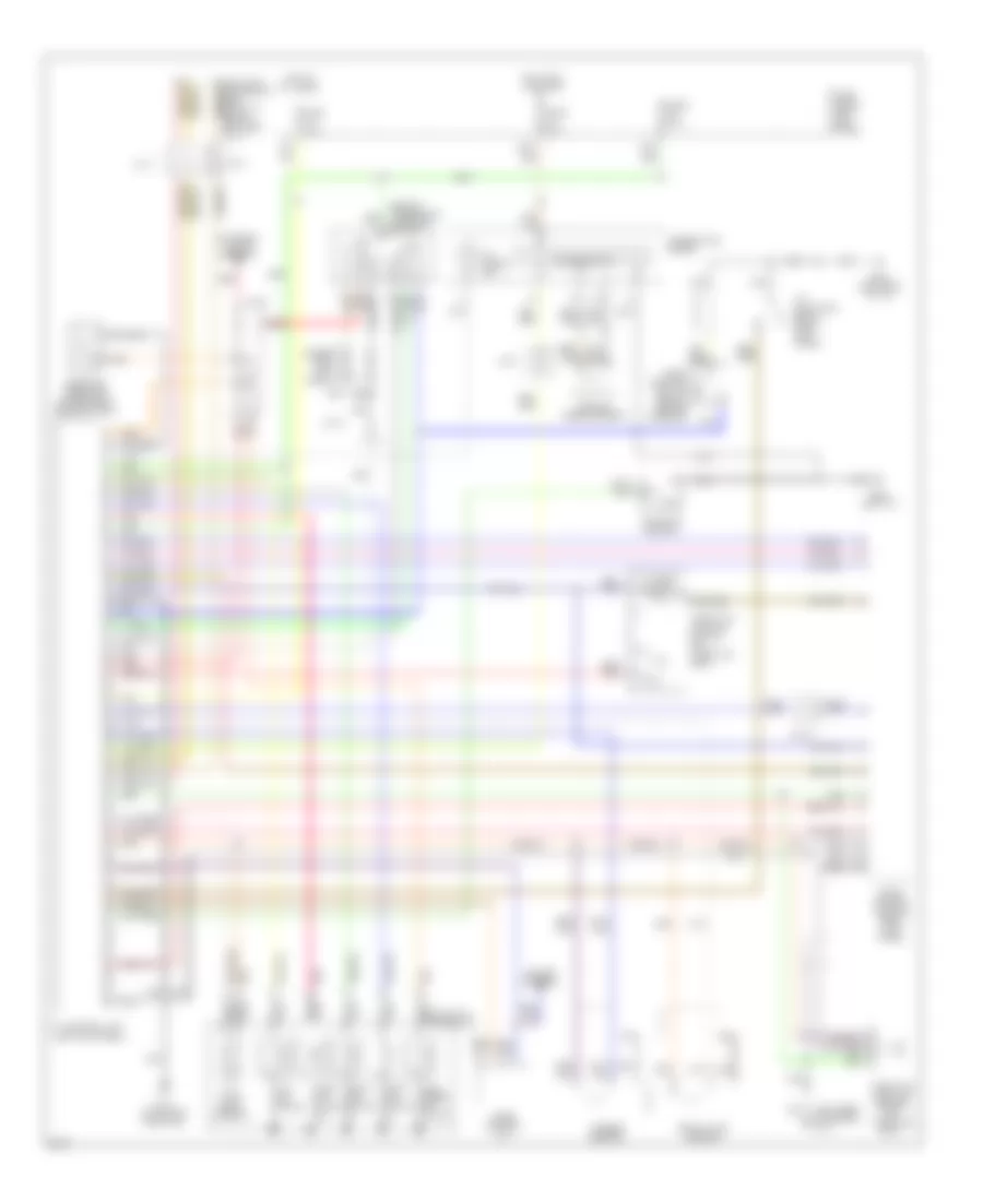
Transmission Wiring Diagram for Infiniti J30 1996
List of elements for Transmission Wiring Diagram for Infiniti J30 1996:
- (left kick panel)
- (left rear of engine) g114
- (side of transaxle) inhibitor switch
- 1-2
- 15g
- 25a
- A/t check ind.
- A/t control unit
- A/t fluid temp. sensor
- A/t indicator relay (right kick panel)
- All times
- Ascd control unit
- Automatic transaxle
- Closed throttle
- Combination meter
- Cruise control
- Data link connector (for consult) (below left side of i/p)
- Diodes (left kick panel)
- Dropping resistor (on bracket, near battery)
- Eccs control module (right kick panel)
- Exterior lights (backup)
- First position switch (below center console)
- Fuse 7.5a
- Fuse block (left kick panel)
- G131 (on intake manifold)
- G200 (left i/p)
- G202 (left side of i/p)
- Hot at
- Hot in on or start
- J/c-10
- J/c-11
- J/c-12
- J/c-6
- J/c-9
- Kickdown switch
- Line press. sol. valve
- Nca
- Over- run clutch sol.
- Pnk
- Red
- Revolution sensor
- Shift sol. valve a
- Shift sol. valve b
- Speed sensor
- Speedometer
- Tcc sol. valve
- Throttle position sensor (on throttle body)
- Throttle position switch (on throttle body)
- Turbine sensor
- Vehicle
- Wot
 Čeština
 Dansk
Dansk Ελληνικά
 English
 English
 Español
 Suomi
Suomi Français
 Français
 עברית
עברית Hrvatski
 Magyar
 Italiano
 日本語
日本語 한국어
한국어 Nederlands
 Polski
 Português
 Português
 Română
 Русский
 Slovenčina
 Slovenščina
 Svenska
 Türkçe
 中文 (中国)
 Deutsch