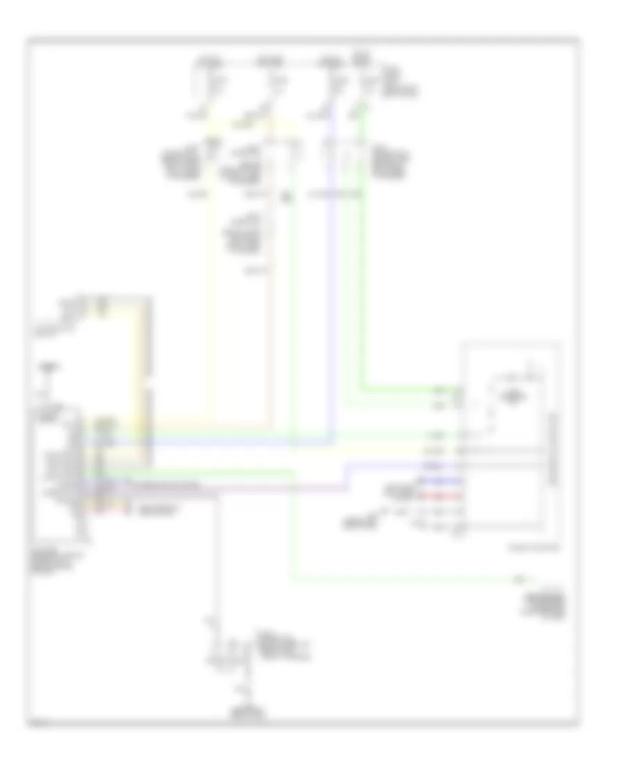
WARNING SYSTEMS
Chime Wiring Diagram for Infiniti M45 2004
 https://portal-diagnostov.com/license.html
Automotive Electricians Portal FZCO
Automotive Electricians Portal FZCO
https://portal-diagnostov.com/license.html
https://portal-diagnostov.com/license.html
Automotive Electricians Portal FZCO
Automotive Electricians Portal FZCO
List of elements for Chime Wiring Diagram for Infiniti M45 2004:
- (behind left side of dash)
- (behind left side of dash) m24
- (w/ icc indicator) unified meter control unit
- 15a
- 1st
- 20b
- 2nd
- 7c m1
- Auto
- B17 (at left front door sill)
- Bat
- Belt ind
- Body control module (bcm) (behind left kick panel)
- Chime
- Combination meter
- Combination switch (lighting switch)
- Door ind
- Door sw (dr)
- Dr warn lamp
- Exterior lights system
- Front door switch (driver side) (at left "b" pillar)
- Front power seat (driver side) (under left front seat)
- Fuse 1 10a
- Fuse 3 10a
- Fuse 32 10a
- Fuse 6 10a
- Fuse 9 10a
- Fuse block (j/b) 1 (behind left end of dash)
- Fuse block (j/b) 2 (behind right kick panel)
- Gnd
- Gnd1
- Gnd2
- Headlamp battery saver control unit
- Hot at all times
- Hot in on or start
- Ign
- Ign sw
- Joint connector (behind upper left side of dash, taped to harness)
- Joint connector (behind upper right side of dash, taped to harness)
- Joint connector 10 (behind upper left end of dash, taped to harness)
- Joint connector 20 (behind upper right side of dash, taped to harness)
- Joint connector 21 (behind upper left side of dash, taped to harness)
- Joint connector 5 (behind upper left side of dash, taped to harness)
- Joint connector 6 (behind right end of dash)
- Key sw
- Key switch & key lock solenoid (at right side of steering column)
- Lt sw (1st)
- M115 (behind right side of dash)
- M145 6n
- M25 (behind left side of dash)
- M33
- M34
- M41
- M42
- Nca
- Off
- Seat belt buckle switch
- Seat blt sw
- T/l sw1
- T/l sw2
- W/ automatic drive positioner
- W/o automatic drive positioner
- Warning chime (behind right side of dash)
Tire Pressure Monitoring Wiring Diagram for Infiniti M45 2004
List of elements for Tire Pressure Monitoring Wiring Diagram for Infiniti M45 2004:
- (behind left
- 19b
- Acc
- Antenna
- Antenna signal
- Batt
- Bus +
- Bus -
- Combination meter
- Commi (bus+)
- Commi (bus-)
- Commi (gnd)
- Computer data lines system
- Diag-id input
- End of dash)
- Exterior lights system
- Fuse 10a
- Fuse block (j/b) 1
- Ground
- Hazard
- Hot at all times
- Hot in acc or on
- Hot in on or start
- Ign
- Joint connector (behind upper left end of dash, taped to harness)
- Joint connector 10 (behind upper left end of dash, taped to harness)
- Joint connector 11 (behind upper right side of dash, taped to harness)
- Joint connector 5 (behind upper left side of dash, taped to harness)
- Led
- Low tire pressure warning control unit (behind center of dash)
- M24 (behind left side of dash)
- M25 (behind left side of dash)
- M41
- M42
- M424
- M84
- Multifunction switch
- Nca
- Pnk
- Red
- Shield
- Speed input
- Tire pressure ind
- Tire pressure warning check connector (under left side of dash)
- Unified meter control unit

 Čeština
 Dansk
Dansk Ελληνικά
 English
 English
 Español
 Suomi
Suomi Français
 Français
 עברית
עברית Hrvatski
 Magyar
 Italiano
 日本語
日本語 한국어
한국어 Nederlands
 Polski
 Português
 Português
 Română
 Русский
 Slovenčina
 Slovenščina
 Svenska
 Türkçe
 中文 (中国)