ANTI-LOCK BRAKES
Anti-lock Brake Wiring Diagrams for Ford Explorer Sport Trac 2002
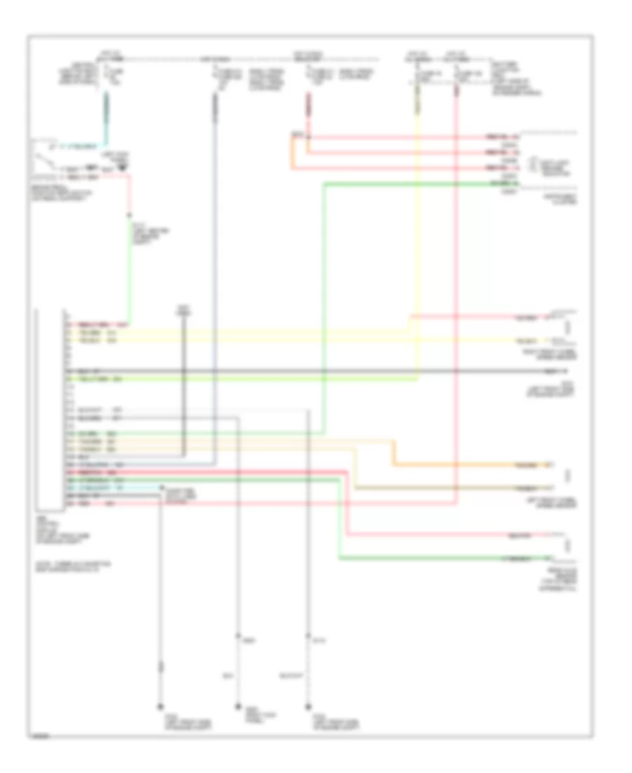
List of elements for Anti-lock Brake Wiring Diagrams for Ford Explorer Sport Trac 2002:
- (early prod) (late prod)
- (early prod) (late prod) (early prod) (late prod)
- (left kick panel) g300
- (not used)
- Abs control module (on left front side of engine compt)
- Anti-lock brakes indicator
- Battery junction box (left side of engine compt, on fender apron)
- Brake pedal position (bpp) switch (on pedal support)
- C220a
- C220b
- C220c
- Central junction box (behind left side of dash)
- Computer data lines system
- Differential)
- Fuse 128 30a
- Fuse 16 50a
- Fuse 211 fuse 22 7.5a
- Fuse 214 fuse 235 10a 5a
- Fuse 7.5a
- G101 (left front side of engine compt)
- G102 (left front side of engine compt)
- G103 (left front side of engine compt)
- G200 (right kick panel)
- Hot at all times
- Hot in run
- Hot in run or start
- Instrument cluster
- Left front wheel speed sensor
- Note: there is a shorting bar across pins 8 & 16
- Rear axle sensor (top of rear
- Red
- Red/pnk
- Right front wheel speed sensor
- S117 (left center of engine compt)
- S118
- S203
- S218
 Čeština
 Dansk
Dansk Ελληνικά
 English
 English
 Español
 Suomi
Suomi Français
 Français
 עברית
עברית Hrvatski
 Magyar
 Italiano
 日本語
日本語 한국어
한국어 Nederlands
 Polski
 Português
 Português
 Română
 Русский
 Slovenčina
 Slovenščina
 Svenska
 Türkçe
 中文 (中国)
 Deutsch