CRUISE CONTROL
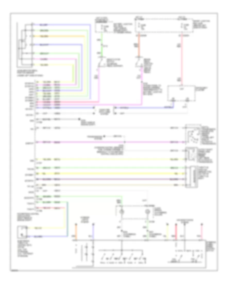
Cruise Control Wiring Diagram for Ford Explorer Sport Trac 2007
List of elements for Cruise Control Wiring Diagram for Ford Explorer Sport Trac 2007:
- (under left side of dash)
- Accelerator pedal position sensor
- Air conditioning system
- App1
- App2
- App3
- Battery junction box (bjb) (left side of engine compt, at fender apron)
- Boo
- Bps
- Brake pedal position switch (above brake pedal)
- C175b
- C175e
- C175t
- C218a
- C218b
- C2280c
- C2280e
- Ccb08
- Ce412
- Ce426
- Ces09
- Clock spring (in steering column)
- Computer data lines system
- Deactivator switch (on brake pedal support)
- Digital transmission range (dtr) sensor (5r55s) (lower left side of automatic transmission)
- Electronic throttle control (etc) motor (4.6l: top of engine) (4.0l: top front of engine)
- Etcref1
- Etcref2
- Etcref3
- Etcrtn1
- Etcrtn2
- Etcrtn3
- Fan down
- Fan up
- Fuse 10a
- Fuse 15a
- G106 (right side of engine compt)
- Gd113
- Gnd
- Hat
- Hot at all times
- Hot w/ pcm power relay energized
- Hs can +
- Hs can -
- Hs can+
- Hs can-
- Instrument cluster
- Interior lights system
- Le134
- Le136
- Le137
- Off
- Oss
- Output shaft speed (oss) sensor (5r55s) (left rear of automatic transmission)
- Pnk
- Powertrain control module (pcm) (right rear of engine compt)
- Re134
- Re136
- Re137
- Re406
- Red
- Res
- Res08
- Ret04
- S106 (in engine control sensor & fuel charge harness, in breakout to powertrain control module (pcm))
- S118
- S128 (in dash panel to engine harness, near breakout to battery junction box (bjb))
- S237 (in steering wheel)
- S238 (in steering wheel)
- Sccs
- Sccs rtn
- Set+
- Set-
- Sigrtnt
- Smart junction box (sjb) (behind left side of dash)
- Solid state
- Steering wheel/ speed control switch
- Tacm n
- Tacm p
- Throttle position sensor (tps) (on top of throttle body)
- Tp1 ns
- Tp2 ps
- Tr1
- Transmissions system
- Vdb04
- Vdb05
- Ve701
- Ve702
- Ve703
- Ve818
- Ve819
- Ves10
- Vet28
 Čeština
 Dansk
Dansk Ελληνικά
 English
 English
 Español
 Suomi
Suomi Français
 Français
 עברית
עברית Hrvatski
 Magyar
 Italiano
 日本語
日本語 한국어
한국어 Nederlands
 Polski
 Português
 Português
 Română
 Русский
 Slovenčina
 Slovenščina
 Svenska
 Türkçe
 中文 (中国)
 Deutsch