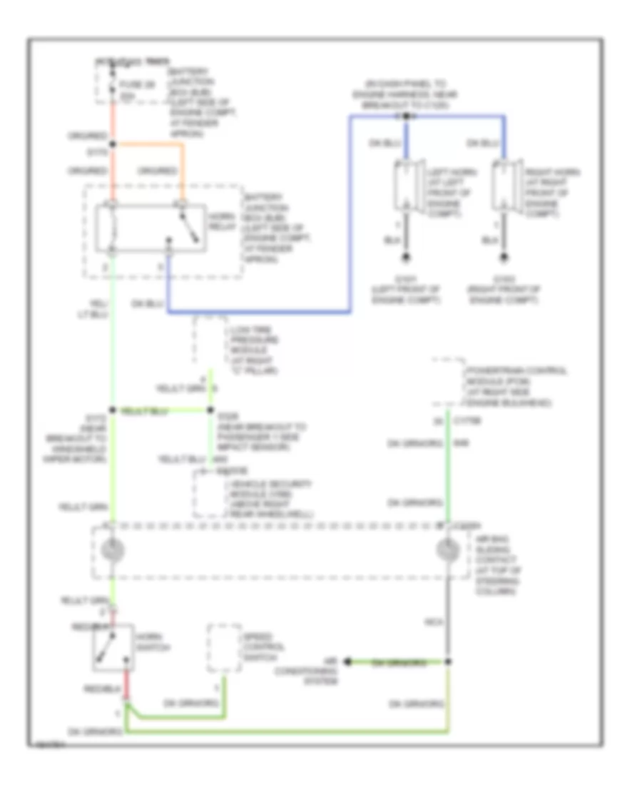
HORN
Horn Wiring Diagram for Ford Explorer 2004
List of elements for Horn Wiring Diagram for Ford Explorer 2004:
- (in dash panel to engine harness, near breakout to c126) s124
- 20a
- Air bag sliding contact (at top of steering column)
- Air conditioning system
- Battery junction box (bjb) (left side of engine compt, at fender apron)
- C175b
- C218a
- C3203e
- Fuse 28
- G101 (left front of engine compt)
- G103 (right front of engine compt)
- Horn relay
- Horn switch
- Hot at all times
- Left horn (at left front of engine compt)
- Low tire pressure module (at right "c" pillar)
- Nca
- Powertrain control module (pcm) (at right side engine bulkhead)
- Right horn (at right front of engine compt)
- S170
- S172 (near breakout to windshield wiper motor)
- S328 (near breakout to passenger 1 side impact sensor)
- Speed control switch
- Vehicle security module (vsm) (above right rear wheelwell)
 Čeština
 Dansk
Dansk Ελληνικά
 English
 English
 Español
 Suomi
Suomi Français
 Français
 עברית
עברית Hrvatski
 Magyar
 Italiano
 日本語
日本語 한국어
한국어 Nederlands
 Polski
 Português
 Português
 Română
 Русский
 Slovenčina
 Slovenščina
 Svenska
 Türkçe
 中文 (中国)
 Deutsch