
 Čeština
 Dansk
Dansk Ελληνικά
 English
 English
 Español
 Suomi
Suomi Français
 Français
 עברית
עברית Hrvatski
 Magyar
 Italiano
 日本語
日本語 한국어
한국어 Nederlands
 Polski
 Português
 Português
 Română
 Русский
 Slovenčina
 Slovenščina
 Svenska
 Türkçe
 中文 (中国)

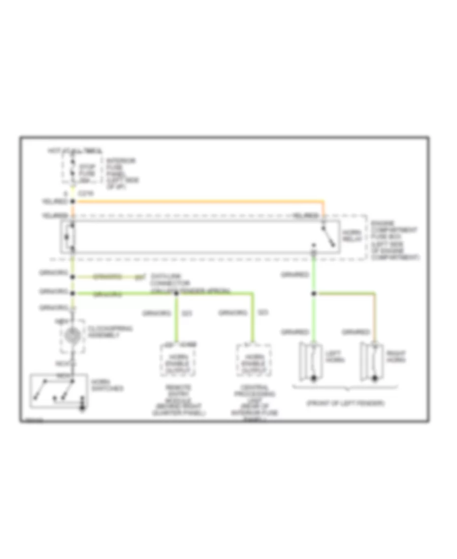
HORN
Horn Wiring Diagram for Ford Probe GT 1995
List of elements for Horn Wiring Diagram for Ford Probe GT 1995:

AIR CONDITIONINGANTI-THEFTANTI-LOCK BRAKESCOOLING FANCOMPUTER DATA LINESEXTERIOR LIGHTSDEFOGGERSENGINE PERFORMANCECRUISE CONTROLHEADLIGHTSINTERIOR LIGHTSGROUND DISTRIBUTIONHORNPOWER DISTRIBUTIONPOWER ANTENNAPOWER TOP/SUNROOFPOWER MIRRORSPOWER DOOR LOCKSRADIOPOWER SEATSPOWER WINDOWSSHIFT INTERLOCKSSTARTING/CHARGINGINSTRUMENT CLUSTERSUPPLEMENTAL RESTRAINTSWARNING SYSTEMSTRANSMISSIONWIPER/WASHER