TRANSMISSION
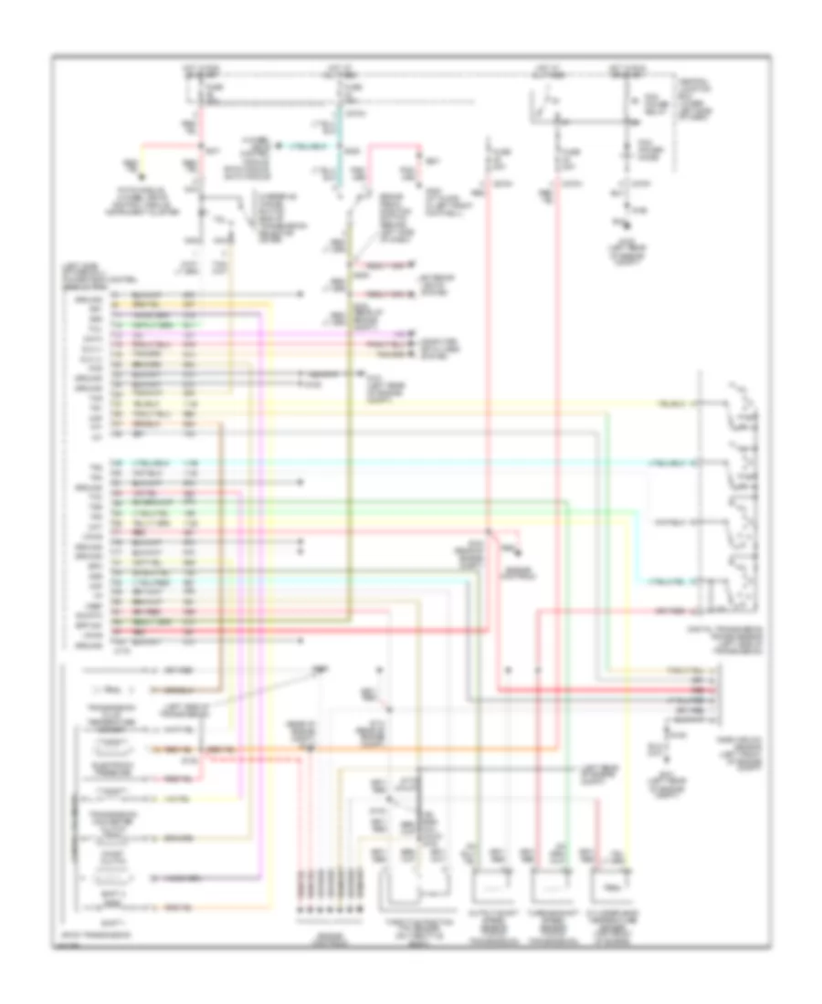
4WD Wiring Diagram for Ford F450 Super Duty 2002
 https://portal-diagnostov.com/license.html
Automotive Electricians Portal FZCO
Automotive Electricians Portal FZCO
https://portal-diagnostov.com/license.html
https://portal-diagnostov.com/license.html
Automotive Electricians Portal FZCO
Automotive Electricians Portal FZCO
List of elements for 4WD Wiring Diagram for Ford F450 Super Duty 2002:
- (left front of engine compt) abs control module
- (left side of transmission) digital transmission range sensor
- (pick-up)
- 4wd hi
- 4wd hi ind
- 4wd lo
- 4wd lo ind
- 4wd sw
- 87a
- Auxiliary relay box 3 (rear of engine compartment)
- Bpp sw
- Brake pedal position switch (behind left side of dash, above brake pedal)
- C135
- C220b
- C270a
- C270h
- C270m
- C281a
- C281b
- C281c
- C350a
- C350b
- Central junction box (lower left side of dash)
- Computer data lines connector
- Data link connector (behind center of dash)
- Dtr sensor, park brake relay, gas: speed control servo, dsl: vacuum pump motor
- Electronic shift-on-the-fly (esof) solenoid (right side of engine compt)
- Esof sol
- Excursion: pats module, eatc module
- Exterior lights system
- Four-wheel drive control module (behind right side of dash)
- Four-wheel drive switch
- Fuse 10a
- Fuse 15a
- Fuse 30a
- G100 (left rear of engine compt)
- G201 (behind left side of dash)
- G300 (at floor, in left front footwell)
- Ground
- Hi to lo
- Hot at all times
- Hot in run
- Hot in run or acc
- Hot in run or start
- Hot in start
- Ign (run/acc)
- Ign (st)
- Ign (st/run)
- Illum
- Instrument cluster
- Instrument cluster, accelerator pedal position sensor, o/d cancel switch, 7.3l: auxiliary pcm
- Instrument cluster, windshield wiper motor, pickup: fuel tank selector switch
- Interior lights system
- Iso bus
- Lo to hi
- Motor 2
- Motor 3
- Motor 4
- Motor 5
- Nuet sens
- Off
- Pickup
- Red
- Ref volt
- Reverse
- S124
- S199
- S201
- S205 (behind left side of dash)
- S225 (behind instrument cluster)
- S228
- S250
- S253 (behind instrument cluster)
- S255 (on transfer case)
- S257
- S271
- Shift sol
- Transfer case assembly
- Transfer case high to low relay
- Transfer case low to high relay
- Vss in
- Vss out
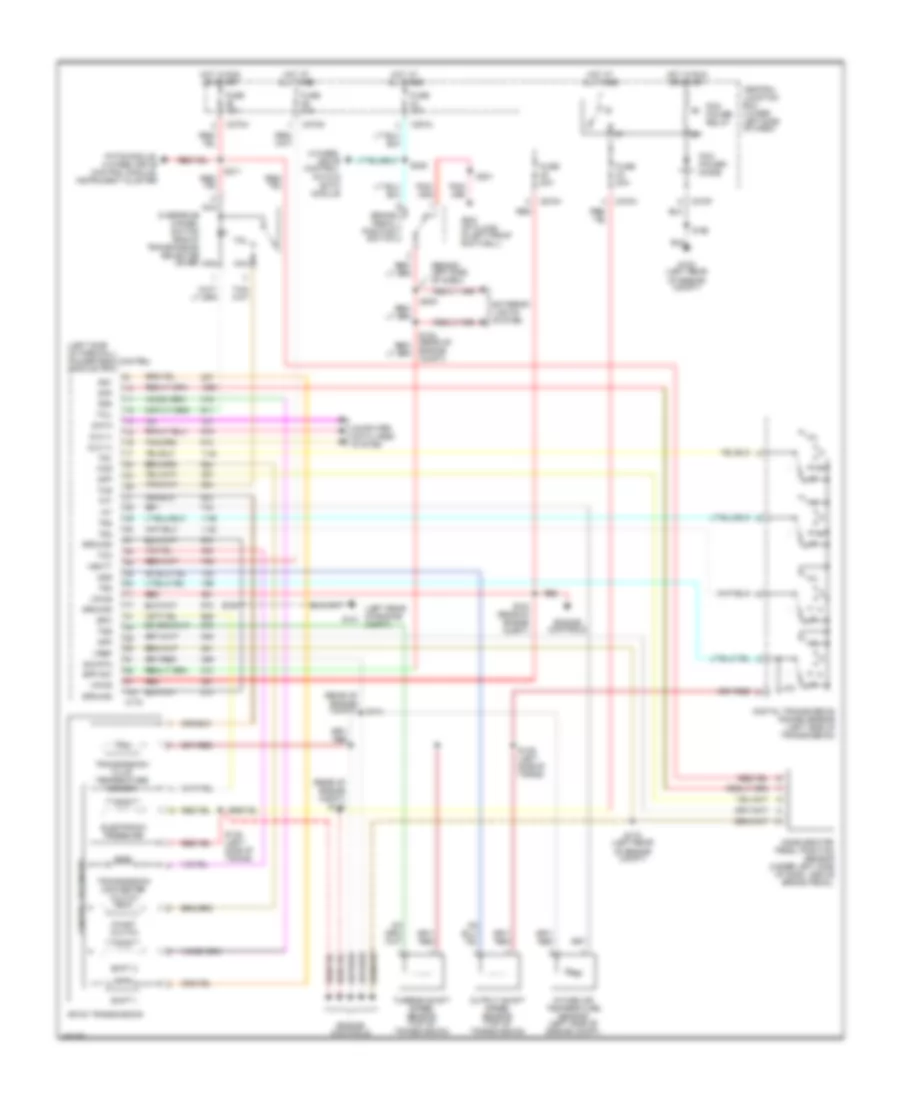
6.8L
6.8L, A/T Wiring Diagram for Ford F450 Super Duty 2002
List of elements for 6.8L, A/T Wiring Diagram for Ford F450 Super Duty 2002:
- (5.4l calif) s133
- (left rear of engine compt)
- (left side of firewall) powertrain control module (pcm)
- (left side of transmission)
- (rear of engine compt) s122
- 4-wheel drive control module, pats module, eatc module
- 4r100 transmission
- Bpp sw
- Brake pedal position switch (behind left side of dash)
- C175
- C270a
- C270f
- C270h
- Ccs
- Central junction box (lower left side of dash)
- Cht
- Coast clutch
- Computer data lines system
- Control solenoids
- Cylinder head temperature sender (top front of engine)
- Data
- Digital transmission range sensor (left side of transmission)
- Dlc (+)
- Dlc (-)
- Electronic pressure
- Engine compt)
- Engine controls
- Epc
- Exterior lights system
- Fuse 10a
- Fuse 20a
- G100 (left rear of engine compt)
- G101 (left rear of engine compt)
- G300 (at floor, in left front footwell)
- Ground
- Hot at all times
- Hot in run or start
- Iat
- Maf
- Mass airlow sensor (left front of engine compt)
- Nca
- Oss
- Output shaft speed sensor (top of transmission)
- Overdrive cancel switch (end of transmission selector lever)
- Pats module, 4-wheel drive control module, instrument cluster
- Pcm power diode
- Pcm power relay
- R p
- Red
- S106
- S114 (rear of engine compt)
- S123 (rear of engine compt)
- S132
- S138
- S139
- S162
- S170 (calif)
- S201
- S205
- S228
- S271
- Shift 1
- Shift 2
- Sig rtn
- Ss1
- Ss2
- Tcc
- Tcil
- Tcs
- Tft
- Throttle position (tp) sensor (on throttle body)
- Tr1
- Tr2
- Tr3
- Tr4
- Transmission converter clutch
- Transmission fluid temperature sensor
- Tss
- Turbine shaft speed sensor (top of transmission)
- Vpwr
- Vref
7.3L DIESEL
7.3L Diesel, A/T Wiring Diagram for Ford F450 Super Duty 2002
List of elements for 7.3L Diesel, A/T Wiring Diagram for Ford F450 Super Duty 2002:
- (behind left side of dash)
- (left rear of engine compt)
- (left side of firewall) powertrain control module (pcm)
- (rear of engine compt)
- (rear of engine compt) s122
- 4-wheel drive control, pats & eatc module
- 4r100 transmission
- Accelerator pedal position sensor (under left side of dash, above brake pedal)
- App
- Bpp sw
- Brake pedal position switch
- C175
- C270a
- C270f
- C270g
- C270h
- Ccs
- Central junction box (lower left side of dash)
- Coast clutch
- Computer data lines system
- Control solenoids
- Data
- Digital transmission range sensor (left side of transmission)
- Dlc (+)
- Dlc (-)
- Electronic pressure
- Engine compt)
- Engine controls
- Epc
- Exterior lights system
- Fuse 10a
- Fuse 20a
- G100 (left rear of engine compt)
- G101
- G300 (at floor, in left front footwell)
- Ground
- Hot at all times
- Hot in run or start
- Iat
- Intake air temperature sensor (left side of engine compt)
- Nca
- Oss
- Output shaft speed sensor (top of transmission)
- Overdrive cancel switch (end of transmission selector lever)
- Pats module, 4-wheel drive control module, instrument cluster
- Pcm power diode
- Pcm power relay
- R p
- Red
- S106
- S114
- S123 (rear of engine compt)
- S138 (left side of trans)
- S139 (left side of trans)
- S162
- S170 (left rear of engine compt)
- S201
- S205
- S228
- S271
- Shift 1
- Shift 2
- Sig rtn
- Ss1
- Ss2
- Tcc
- Tcil
- Tcs
- Tft
- Tr1
- Tr2
- Tr3
- Tr4
- Transmission converter clutch
- Transmission fluid temperature sensor
- Tss
- Turbine shaft speed sensor (top of transmission)
- Vbatt
- Vpwr
- Vref

 Čeština
 Dansk
Dansk Ελληνικά
 English
 English
 Español
 Suomi
Suomi Français
 Français
 עברית
עברית Hrvatski
 Magyar
 Italiano
 日本語
日本語 한국어
한국어 Nederlands
 Polski
 Português
 Português
 Română
 Русский
 Slovenčina
 Slovenščina
 Svenska
 Türkçe
 中文 (中国)