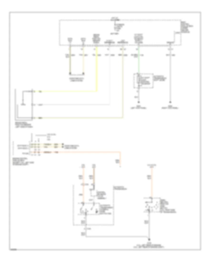
SHIFT INTERLOCK
Shift Interlock Wiring Diagram for Pontiac G6 GXP 2010
List of elements for Shift Interlock Wiring Diagram for Pontiac G6 GXP 2010:
- (pnp) switch (3.5l: right side of transmission)
- 2.4l
- 2.4l & 3.5l (a/t)
- 3.5l & 3.9l
- 3.6l
- 3.6l (a/t)
- 3.9l (a/t)
- 5 volt reference
- A/t shift lock control solenoid
- Automatic transmission
- Automatic transmission internal mode switch (ims)
- Automatic transmission shift lever
- Battery
- Body control module (bcm) (under center console)
- Brake pedal position sensor (left side of dash)
- Brake pedal position sensor signal
- Computer data lines system
- Control solenoid valve assembly
- Data bus (+)
- Data bus (-)
- Engine control module (ecm) (except 3.6l: left side of engine compt)
- G105 (2.4l: left rear of engine) (3.5l: left rear of engine compt)
- G303 (left kick panel)
- G305 (right kick panel)
- Ground
- Hot at all times
- Interior lights fuse 10a
- K x100
- Logic
- Low reference
- Nca
- P/n sig
- Park/ neutral position
- Tan
- Tan/
- W x100
 Čeština
 Dansk
Dansk Ελληνικά
 English
 English
 Español
 Suomi
Suomi Français
 Français
 עברית
עברית Hrvatski
 Magyar
 Italiano
 日本語
日本語 한국어
한국어 Nederlands
 Polski
 Português
 Português
 Română
 Русский
 Slovenčina
 Slovenščina
 Svenska
 Türkçe
 中文 (中国)
 Deutsch