
 Čeština
 Dansk
Dansk Ελληνικά
 English
 English
 Español
 Suomi
Suomi Français
 Français
 עברית
עברית Hrvatski
 Magyar
 Italiano
 日本語
日本語 한국어
한국어 Nederlands
 Polski
 Português
 Português
 Română
 Русский
 Slovenčina
 Slovenščina
 Svenska
 Türkçe
 中文 (中国)

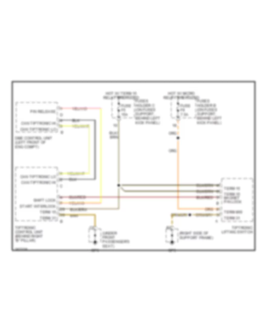
SHIFT INTERLOCK
Shift Interlock Wiring Diagram for Porsche 911 Turbo 2007
List of elements for Shift Interlock Wiring Diagram for Porsche 911 Turbo 2007:

COMPUTER DATA LINESANTI-LOCK BRAKESCRUISE CONTROLAIR CONDITIONINGCOOLING FANELECTRONIC MUFFLERBODY CONTROL MODULESANTI-THEFTDEFOGGERSHORNEXTERIOR LIGHTSGROUND DISTRIBUTIONENGINE PERFORMANCEHEADLIGHTSELECTRONIC SUSPENSIONPOWER DOOR LOCKSINTERIOR LIGHTSMEMORY SYSTEMSPOWER MIRRORSNAVIGATIONPOWER WINDOWSPOWER SEATSINSTRUMENT CLUSTERPOWER TOP/SUNROOFSTARTING/CHARGINGRADIOPOWER DISTRIBUTIONSHIFT INTERLOCKTRANSMISSIONSUPPLEMENTAL RESTRAINTSWIPER/WASHERWARNING SYSTEMSTRUNK, TAILGATE, FUEL DOOR