DEFOGGERS
Defogger Wiring Diagram for BMW 325is 1992


List of elements for Defogger Wiring Diagram for BMW 325is 1992:
- (not used)
- Antenna amplifier am/fm (lower left "c" pillar)
- Front power distribution box (left rear side of engine compartment)
- Fuse 23 5a
- Fuse 6 20a
- G201 (below right side of dash)
- G310 (sedan) (upper right rear seatback)
- G312 (coupe) (upper left rear seatback)
- Ground
- Hot at all times
- Hot in run and start
- Ihkr control panel
- Integrated climate regulation control module (center console)
- Nca
- Rear defogger relay (front power distribution box)
- Rear defogger switch
- Rear defogger/ antenna
- Rear window defogger activation
- Rear window defogger switch
- Suppression filter (lower right "c" pillar)
- X18155
- X18156
- X18157
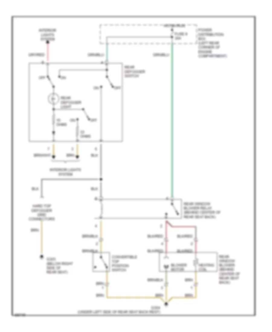
Defogger Wiring Diagram, Convertible for BMW 325is 1992
List of elements for Defogger Wiring Diagram, Convertible for BMW 325is 1992:
- Blower motor
- Convertible top position switch
- Fuse 8 30a
- G303 (below right side of rear seat)
- G304 (under left side of rear seat back rest)
- Hard top defogger grid connectors
- Heating coil
- Hot in run
- Interior lights system
- Off
- Ohms
- Power distribution box (left rear corner of engine compartment)
- Rear defogger light
- Rear defogger switch
- Rear window blower (behind center of rear seat back)
- Rear window blower relay (behind center of rear seat back)

 Čeština
 Dansk
Dansk Ελληνικά
 English
 English
 Español
 Suomi
Suomi Français
 Français
 עברית
עברית Hrvatski
 Magyar
 Italiano
 日本語
日本語 한국어
한국어 Nederlands
 Polski
 Português
 Português
 Română
 Русский
 Slovenčina
 Slovenščina
 Svenska
 Türkçe
 中文 (中国)