COOLING FAN
Auxiliary Cooling Fan Wiring Diagram, Convertible for BMW 325is 1992

List of elements for Auxiliary Cooling Fan Wiring Diagram, Convertible for BMW 325is 1992:
- A/c input
- A/c request input
- A/c select switch
- Auxiliary fan (in front of radiator)
- Auxiliary fan normal speed blower resistor (6 ohms) (in front of radiator, left side of auxiliary fan)
- C114
- Closed above o 196 f o (91 c)
- Closed above o 210 f o (99 c)
- Control switches
- Diode
- Dual temperature switch (top right side of radiator)
- Evaporator temperature regulator (on left side of evaporator housing)
- Fuse 18 30a
- Fuse 19 7.5a
- Fuse 20 30a
- Fuse 3 15a
- G106 (on inner fender, behind left headlight)
- G202 (behind left side of dash, above brake pedal)
- Hot at all times
- Hot in run only from unloader relay k7
- K1 normal speed relay
- K6 high speed relay
- Motronic control unit (behind right side of dash, above glove box)
- Off
- Power distribution box (left rear corner of engine compartment)
- Red
- Some vehicles use an additional splice (s325). see ground distribution for details.
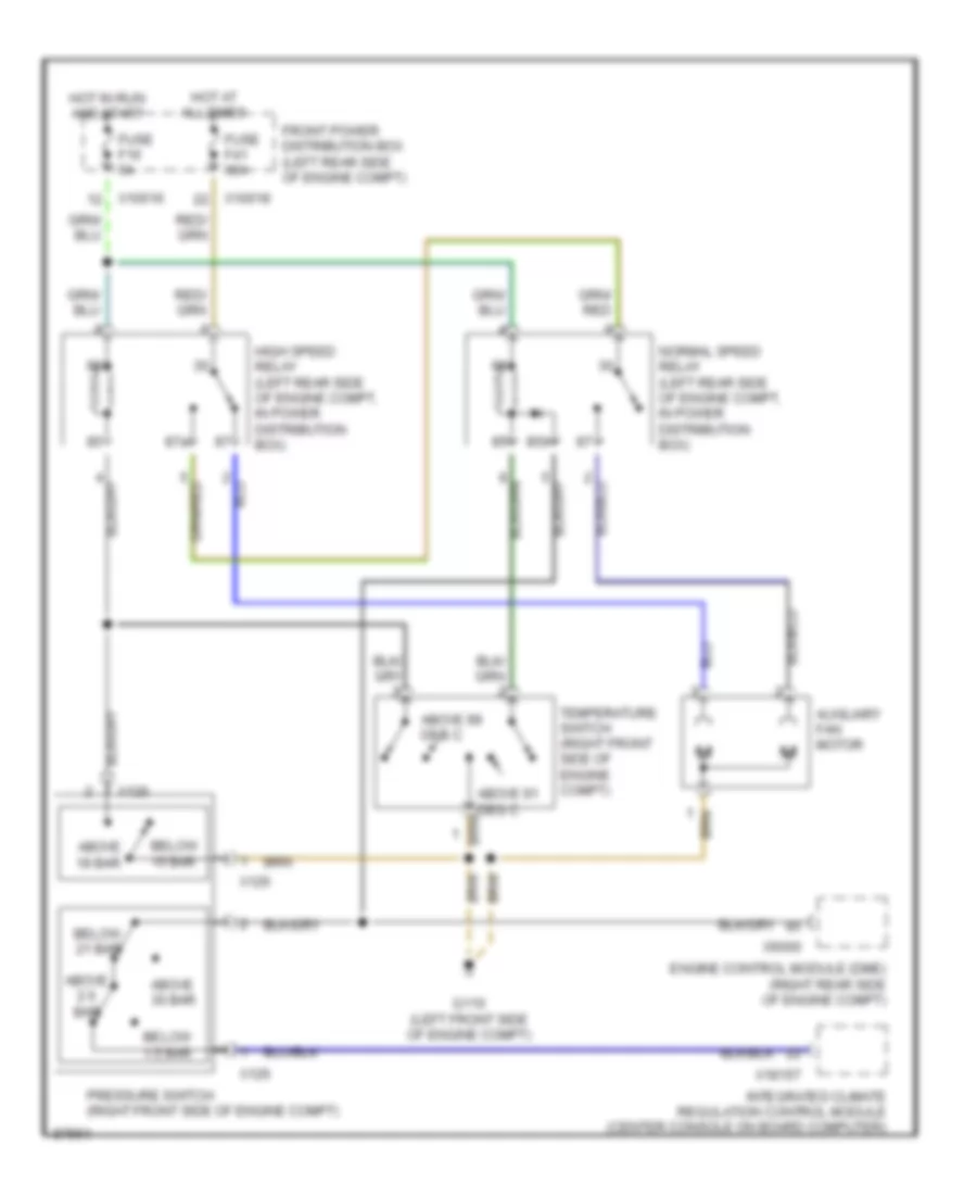
Auxiliary Cooling Fan Wiring Diagram, Except Convertible for BMW 325is 1992
List of elements for Auxiliary Cooling Fan Wiring Diagram, Except Convertible for BMW 325is 1992:
- 85b
- 87a
- Above 18 bar
- Above 2.6 bar
- Above 30 bar
- Above 91 deg c
- Above 99 deg c
- Auxiliary fan motor
- Below 1.5 bar
- Below 15 bar
- Below 21 bar
- Engine control module (dme) (right rear side of engine compt)
- Front power distribution box (left rear side of engine compt)
- Fuse f16 5a
- Fuse f41 30a
- G110 (left front side of engine compt)
- High speed relay (left rear side of engine compt, in power distribution box)
- Hot at all times
- Hot in run and start
- Integrated climate regulation control module (center console on board computer)
- Normal speed relay (left rear side of engine compt, in power distribution box)
- Pressure switch (right front side of engine compt)
- Temperature switch (right front side of engine compt)
- X10016
- X10018
- X126
- X18157
- X6000