SHIFT INTERLOCKS
Shift Interlock Wiring Diagram for BMW Z3 1998
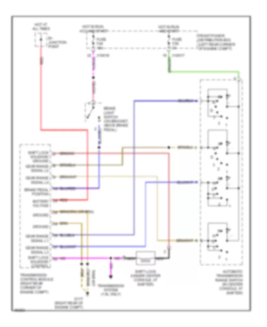
List of elements for Shift Interlock Wiring Diagram for BMW Z3 1998:
- Automatic transmission range switch (in center console, at shifter)
- B+ junction point
- Battery voltage
- Brake light switch (on bracket, above brake pedal)
- Brake pedal position
- Front power distribution box (left rear corner of engine compt)
- Fuse f28 5a
- Fuse f46 15a
- G117 (right rear of engine compt)
- Gear range signal l1
- Gear range signal l2
- Gear range signal l3
- Gear range signal l4
- Ground
- Hot at all times
- Hot in run and start
- Hot in run, acc and start
- Nca
- Red
- Shift lock solenoid control
- Shift lock solenoid ground
- Shift-lock (under center console, at shifter)
- Transmission control module (right rear corner of engine compt)
- Transmission system (1.9l only)
- X10017
- X10018
 Čeština
 Dansk
Dansk Ελληνικά
 English
 English
 Español
 Suomi
Suomi Français
 Français
 עברית
עברית Hrvatski
 Magyar
 Italiano
 日本語
日本語 한국어
한국어 Nederlands
 Polski
 Português
 Português
 Română
 Русский
 Slovenčina
 Slovenščina
 Svenska
 Türkçe
 中文 (中国)
 Deutsch