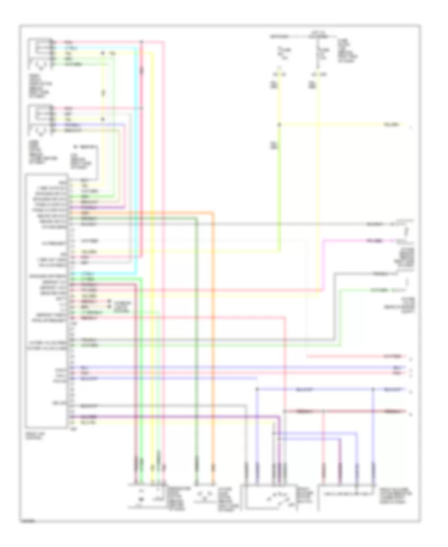
AIR CONDITIONING
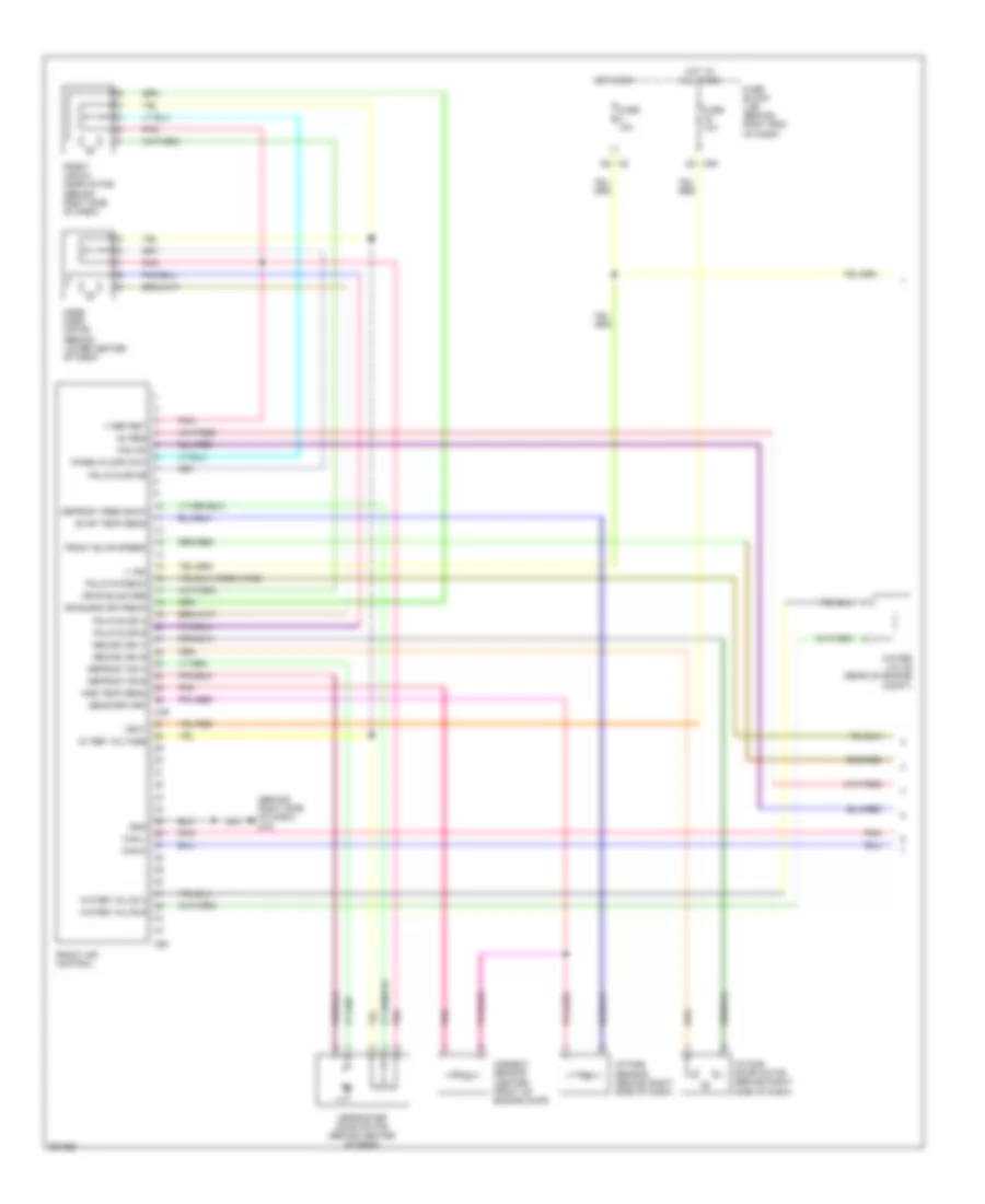
Automatic A/C Wiring Diagram (1 of 3) for Nissan Titan SE 2008
 https://portal-diagnostov.com/license.html
Automotive Electricians Portal FZCO
Automotive Electricians Portal FZCO
https://portal-diagnostov.com/license.html
https://portal-diagnostov.com/license.html
Automotive Electricians Portal FZCO
Automotive Electricians Portal FZCO
List of elements for Automatic A/C Wiring Diagram (1 of 3) for Nissan Titan SE 2008:
- (behind right side of dash)
- (crew cab)
- 5v ref volatage
- Ac req
- Ambient sensor (center front of engine comp)
- Ambient temp sens
- Can-h
- Can-l
- Defrost dr a
- Defrost dr b
- Defrost feed back
- Defroster door motor (behind center of dash)
- Driver air mix door motor (behind right side of dash)
- Drvr blnd dr a
- Drvr blnd dr b
- Drvrt blnd dr ff
- Evap temp sens
- Fan on
- Fr blwr request
- Front air control
- Front blower spd
- Fuse 10a
- Fuse block (j/b) (behind right end of dash)
- Gnd
- Hot at all times
- Hot in on
- In vehicle sensor (behind center of dash)
- In-car sens
- In-car tmp mtr+
- Intake door motor (behind right side of dash)
- Intake sensor (behind right side of dash)
- M39
- M49
- M50
- M79
- M79 (behind right side of dash)
- Mode door motor (behind lower center of dash)
- Optical sensor (top of right side of dash)
- Pass blnd dr a
- Pass blnd dr b
- Pass blnd dr fb
- Passenger air mix door motor (behind center of dash)
- Pnk
- Pnl/flr dr a
- Pnl/flr dr b
- Pnl/flr dr fb
- Rear def req
- Recirc dr1 a
- Recirc dr1 b
- Sun ld sens lft
- Sun ld sens rh
- V bat
- V ign
- V ref ret
- Water valve (rear of (rear of engine comp) engine comp)
- Water valve a
- Water valve b
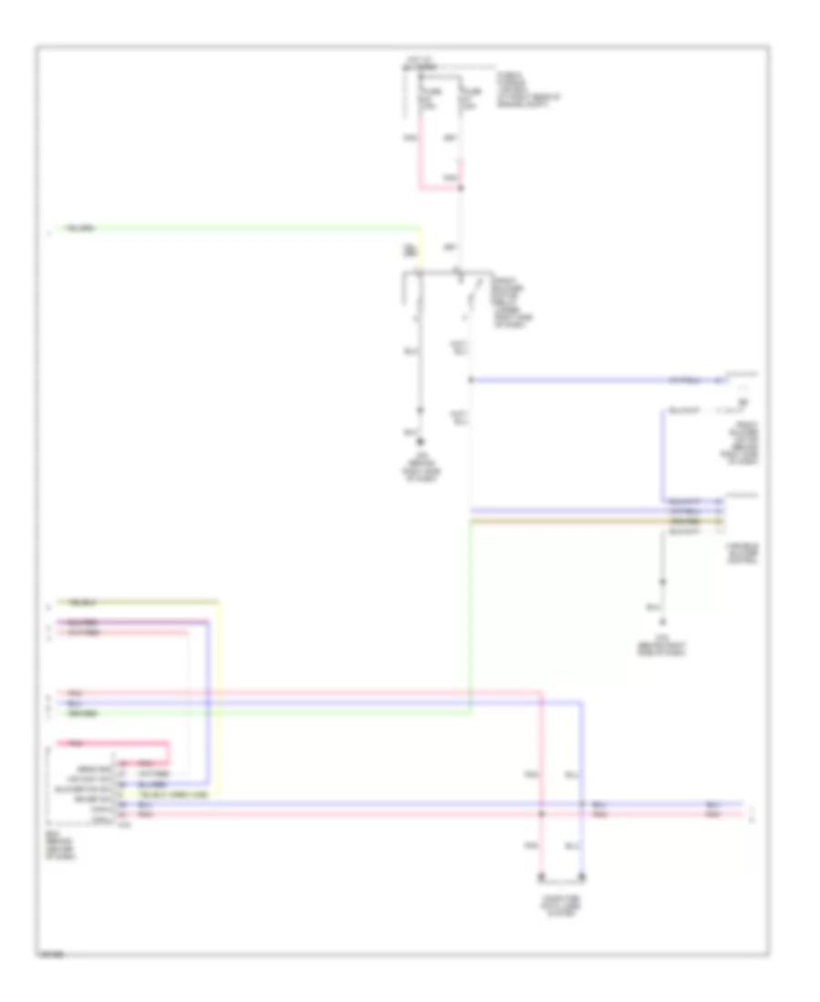
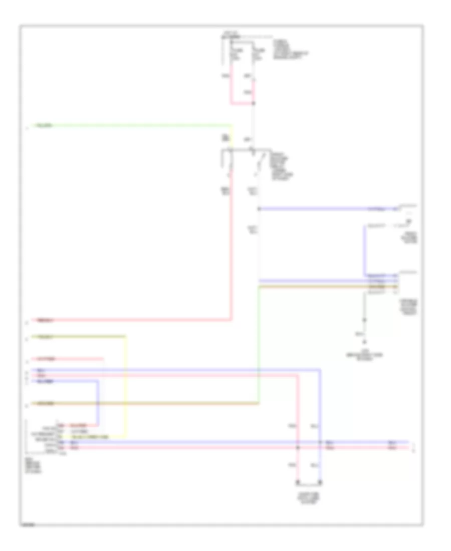
Automatic A/C Wiring Diagram (2 of 3) for Nissan Titan SE 2008
List of elements for Automatic A/C Wiring Diagram (2 of 3) for Nissan Titan SE 2008:
- (crew cab)
- Air cont sw
- Bcm (behind center of dash)
- Blower fan sw
- Can-h
- Can-l
- Computer data lines system
- Front blower motor (behind right side of dash)
- Front blower motor relay (under right side of dash)
- Fuse & fusible link box (at right rear of engine compt)
- Fuse 20a
- Hot at all times
- M18
- M79 (behind right side of dash)
- Pnk
- Rr def sw
- Sens gnd
- Variable blower control
Automatic A/C Wiring Diagram (3 of 3) for Nissan Titan SE 2008
List of elements for Automatic A/C Wiring Diagram (3 of 3) for Nissan Titan SE 2008:
- A/c compressor (at lower left front of engine)
- A/c relay
- Ac com
- Avcc
- Can-h
- Can-l
- Cooling fan motor (at center front of engine compt)
- Cooling fan relay
- Cpu
- E119
- E120
- E122
- E124
- E15 (at right side of engine compt)
- E16
- E24 (at left front of engine compt)
- Ecm (at right side of engine compt)
- Engine coolant temperature sensor (at left front of engine)
- F54
- Fan motor
- Fuse & fusible link box (at right rear of engine compt)
- Fuse 10a
- Fuse 20a
- Fusible link l 40a
- Gnd (power)
- Gnd (signal)
- Gnd-a
- Hot at all times
- Hot in on or start
- Ig+
- Ignition relay
- Ipdm e/r (at right rear of engine compt)
- Pdpress
- Pnk
- Refrigerant pressure sensor (at center front of engine compt)
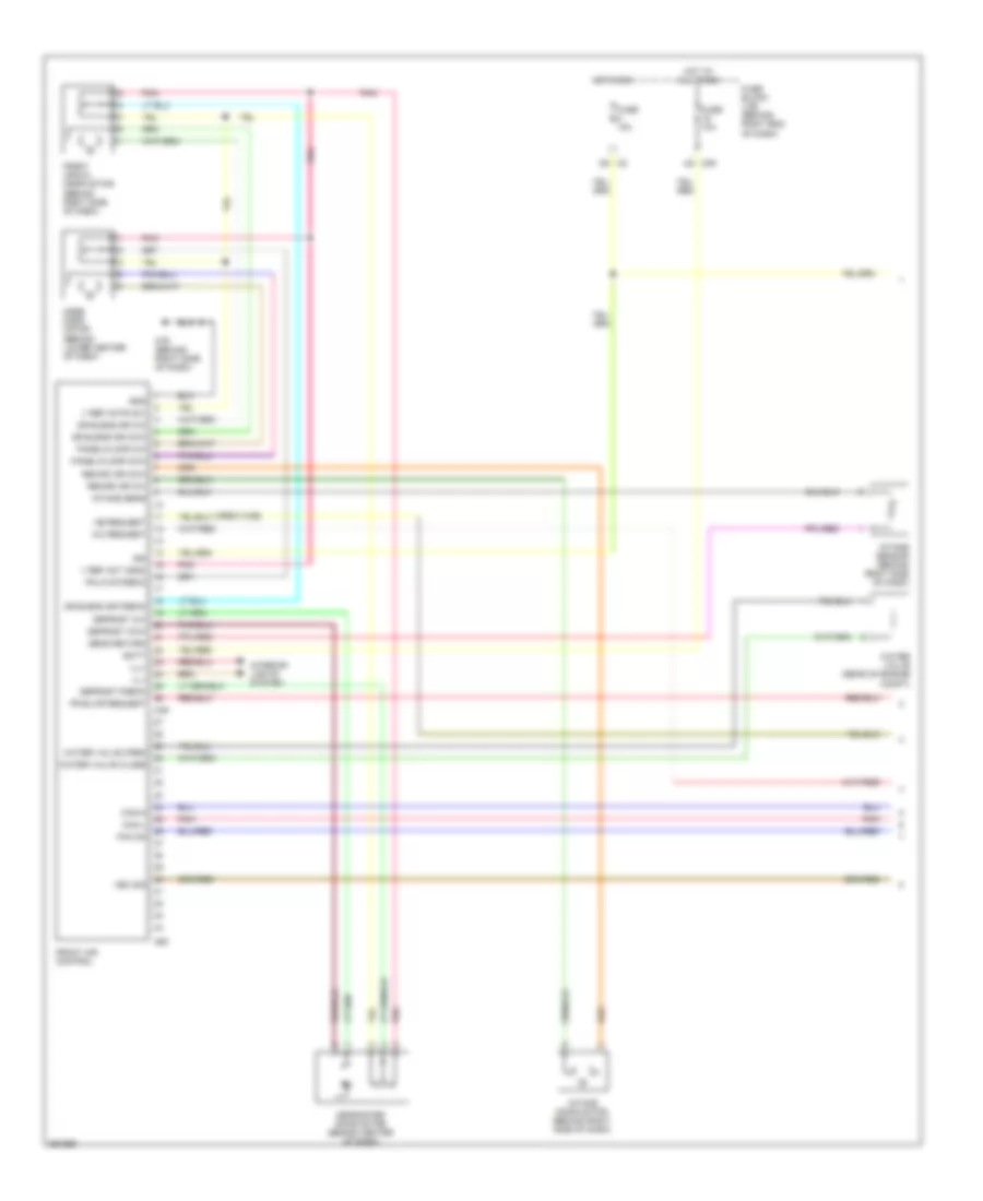
Manual A/C Wiring Diagram, 2 Control Dial System (1 of 3) for Nissan Titan SE 2008
List of elements for Manual A/C Wiring Diagram, 2 Control Dial System (1 of 3) for Nissan Titan SE 2008:
- (behind right side of dash) m79
- (crew cab)
- 4q m39
- 5n m3
- 5v ref voltage
- Ac req
- Amb temp sens
- Ambient sensor (center front of engine comp)
- Can-h
- Can-l
- Defrost dr a
- Defrost dr b
- Defrost feed back
- Defroster door motor (behind center of dash)
- Dr blend dr fdbck
- Drvr blnd drb
- Evap temp sens
- Fan on
- Front air control
- Front air mix door motor (behind right side of dash)
- Front blwr speed
- Fuse 10a
- Fuse block (j/b) (behind right end of dash)
- Gnd
- Hot at all times
- Hot in on
- Intake door motor (behind right side of dash)
- Intake sensor (behind right side of dash)
- M49
- M50
- Mode door motor (behind lower center of dash)
- Panel/floor ccw
- Pnk
- Pnl/flr dr a
- Pnl/flr dr b
- Pnl/flr dr fb
- Pnl/flr fdbck
- Recirc dri a
- Recirc dri b
- Sens return
- V ign
- V ref ret
- Vbat
- Water valve (rear of engine compt)
- Water valve a
- Water valve b
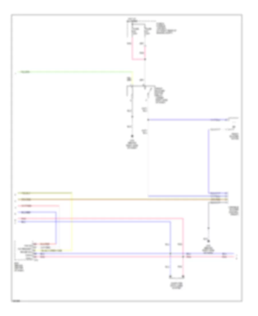
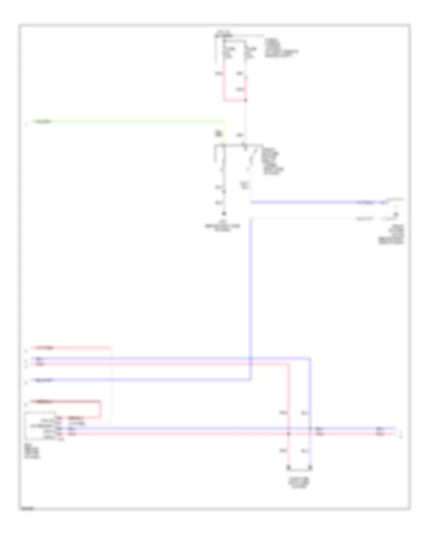
Manual A/C Wiring Diagram, 2 Control Dial System (2 of 3) for Nissan Titan SE 2008
List of elements for Manual A/C Wiring Diagram, 2 Control Dial System (2 of 3) for Nissan Titan SE 2008:
- (crew cab)
- A/c request
- Bcm (behind center of dash)
- Can-h
- Can-l
- Computer data lines system
- Fan on
- Front blower motor
- Front blower motor relay (under right side of dash)
- Fuse & fusible link box (at right rear of engine compt)
- Fuse 20a
- Hot at all times
- M18
- M79 (behind right side of dash)
- Pnk
- Rr def sw
- Variable blower control (front)
Manual A/C Wiring Diagram, 2 Control Dial System (3 of 3) for Nissan Titan SE 2008
List of elements for Manual A/C Wiring Diagram, 2 Control Dial System (3 of 3) for Nissan Titan SE 2008:
- A/c compressor (at lower left front of engine)
- A/c relay
- Ac com
- Avcc
- Can-h
- Can-l
- Cooling fan motor (at center front of engine compt)
- Cooling fan relay
- Cpu
- E119
- E120
- E122
- E124
- E15 (at right side of engine compt)
- E16
- E24 (at left front of engine compt)
- Ecm (at right side of engine compt)
- Engine coolant temperature sensor (at left front of engine)
- F54
- Fan motor
- Fuse & fusible link box (at right rear of engine compt)
- Fuse 10a
- Fuse 20a
- Fusible link l 40a
- Gnd (power)
- Gnd (signal)
- Gnd-a
- Hot at all times
- Hot in on or start
- Ig+
- Ignition relay
- Ipdm e/r (at right rear of engine compt)
- Pdpress
- Pnk
- Refrigerant pressure sensor (at center front of engine compt)
Manual A/C Wiring Diagram, 3 Control Dial System with VBC (1 of 3) for Nissan Titan SE 2008
List of elements for Manual A/C Wiring Diagram, 3 Control Dial System with VBC (1 of 3) for Nissan Titan SE 2008:
- (crew cab)
- 4q m39
- 5n m3
- A/c request
- Batt
- Can-h
- Can-l
- Defrost ccw
- Defrost cw
- Defrost fdbck
- Defroster door motor (behind center of dash)
- Dr blend dr ccw
- Dr blend dr cw
- Dr blend dr fdbck
- Fan on
- Fr blwr request
- Front air control
- Front air mix door motor (behind right side of dash)
- Fuse 10a
- Fuse block (j/b) (behind right end of dash)
- Gnd
- Hb request
- Hot at all times
- Hot in on
- Ign
- Ill+
- Ill-
- Intake door motor (behind right side of dash)
- Intake sens
- Intake sensor (behind right side of dash)
- Interior lights system
- M49
- M50
- M79 (behind right side of dash)
- Mode door motor (behind lower center of dash)
- Panel/floor ccw
- Panel/floor cw
- Pnk
- Pnl/flr fdbck
- Recirc dr ccw
- Recirc dr cw
- Sens return
- V ref act (gnd)
- V ref actr (5v)
- Vbc sig
- Water valve (rear of engine compt)
- Water valve close
- Water valve open
Manual A/C Wiring Diagram, 3 Control Dial System with VBC (2 of 3) for Nissan Titan SE 2008
List of elements for Manual A/C Wiring Diagram, 3 Control Dial System with VBC (2 of 3) for Nissan Titan SE 2008:
- (crew cab)
- A/c request
- Bcm (behind center of dash)
- Can-h
- Can-l
- Computer data lines system
- Fan on
- Front blower motor
- Front blower motor relay (under right side of dash)
- Fuse & fusible link box (at right rear of engine compt)
- Fuse 20a
- Hot at all times
- M18
- M79 (behind right side of dash)
- Pnk
- Rr def sw
- Variable blower control (front)
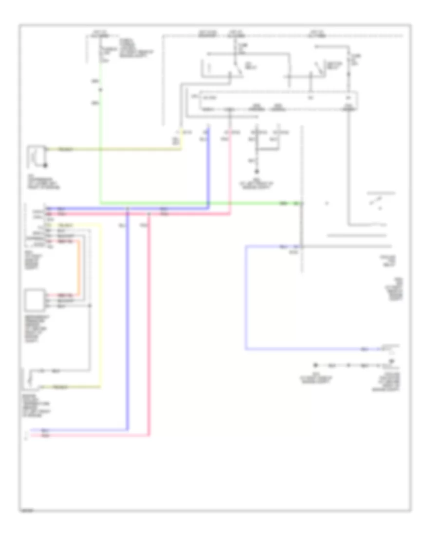
Manual A/C Wiring Diagram, 3 Control Dial System with VBC (3 of 3) for Nissan Titan SE 2008
List of elements for Manual A/C Wiring Diagram, 3 Control Dial System with VBC (3 of 3) for Nissan Titan SE 2008:
- A/c compressor (at lower left front of engine)
- A/c relay
- Ac com
- Avcc
- Can-h
- Can-l
- Cooling fan motor (at center front of engine compt)
- Cooling fan relay
- Cpu
- E119
- E120
- E122
- E124
- E15 (at right side of engine compt)
- E16
- E24 (at left front of engine compt)
- Ecm (at right side of engine compt)
- Engine coolant temperature sensor (at left front of engine)
- F54
- Fan motor
- Fuse & fusible link box (at right rear of engine compt)
- Fuse 10a
- Fuse 20a
- Fusible link l 40a
- Gnd (power)
- Gnd (signal)
- Gnd-a
- Hot at all times
- Hot in on or start
- Ig+
- Ignition relay
- Ipdm e/r (at right rear of engine compt)
- Pdpress
- Pnk
- Refrigerant pressure sensor (at center front of engine compt)
Manual A/C Wiring Diagram, 3 Control Dial System without VBC (1 of 3) for Nissan Titan SE 2008
List of elements for Manual A/C Wiring Diagram, 3 Control Dial System without VBC (1 of 3) for Nissan Titan SE 2008:
- 4q m39
- 5n m3
- A/c request
- Batt
- Can-h
- Can-l
- Defrost ccw
- Defrost cw
- Defrost fdbck
- Defroster door motor (behind center of dash)
- Dr blend dr ccw
- Dr blend dr cw
- Dr blend dr fdbck
- Fan on
- Fr blwr request
- Front air control
- Front air mix door motor (behind right side of dash)
- Front blower motor resistor (under right side of dash)
- Front blower motor switch
- Fuse 10a
- Fuse block (j/b) (behind right end of dash)
- Gnd
- Hot at all times
- Hot in on
- Ign
- Ill+
- Ill-
- Intake door motor (behind right side of dash)
- Intake sens
- Intake sensor (behind right side of dash)
- Interior lights system
- M49
- M50
- M79 (behind right side of dash)
- Mode door motor (behind lower center of dash)
- Off
- Panel/floor ccw
- Panel/floor cw
- Pnk
- Pnl/flr fdbck
- Recirc dr ccw
- Recirc dr cw
- Sens return
- V ref act (gnd)
- V ref actr (5v)
- Vbc sig
- Water valve (rear of engine compt)
- Water valve close
- Water valve open
Manual A/C Wiring Diagram, 3 Control Dial System without VBC (2 of 3) for Nissan Titan SE 2008
List of elements for Manual A/C Wiring Diagram, 3 Control Dial System without VBC (2 of 3) for Nissan Titan SE 2008:
- A/c request
- Bcm (behind center of dash)
- Can-h
- Can-l
- Computer data lines system
- Fan on
- Front blower motor (behind right side of dash)
- Front blower motor relay (under right side of dash)
- Fuse & fusible link box (at right rear of engine compt)
- Fuse 20a
- Hot at all times
- M18
- M79 (behind right side of dash)
- Pnk
Manual A/C Wiring Diagram, 3 Control Dial System without VBC (3 of 3) for Nissan Titan SE 2008
List of elements for Manual A/C Wiring Diagram, 3 Control Dial System without VBC (3 of 3) for Nissan Titan SE 2008:
- A/c compressor (at lower left front of engine)
- A/c relay
- Ac com
- Avcc
- Can-h
- Can-l
- Cooling fan motor (at center front of engine compt)
- Cooling fan relay
- Cpu
- E119
- E120
- E122
- E124
- E15 (at right side of engine compt)
- E16
- E24 (at left front of engine compt)
- Ecm (at right side of engine compt)
- Engine coolant temperature sensor (at left front of engine)
- F54
- Fan motor
- Fuse & fusible link box (at right rear of engine compt)
- Fuse 10a
- Fuse 20a
- Fusible link l 40a
- Gnd (power)
- Gnd (signal)
- Gnd-a
- Hot at all times
- Hot in on or start
- Ig+
- Ignition relay
- Ipdm e/r (at right rear of engine compt)
- Pdpress
- Pnk
- Refrigerant pressure sensor (at center front of engine compt)

 Čeština
 Dansk
Dansk Ελληνικά
 English
 English
 Español
 Suomi
Suomi Français
 Français
 עברית
עברית Hrvatski
 Magyar
 Italiano
 日本語
日本語 한국어
한국어 Nederlands
 Polski
 Português
 Português
 Română
 Русский
 Slovenčina
 Slovenščina
 Svenska
 Türkçe
 中文 (中国)