CRUISE CONTROL
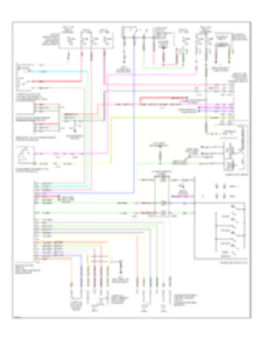
Cruise Control Wiring Diagram for Mitsubishi Outlander GT 2010
List of elements for Cruise Control Wiring Diagram for Mitsubishi Outlander GT 2010:
- (3.0l)
- (behind left side of dash) transaxle control module
- (main)
- (or pnk)
- (or red)
- (sub)
- (under steering wheel) clock spring
- 2.4l
- 3.0l
- A-12
- A-13
- Accelerator pedal position sensor (top of accelerator pedal bracket)
- Anti-lock brakes system
- B-10
- B-11
- C-129
- C-202
- C-204
- C-301
- C-304
- C-312
- C-313
- C-317
- C-34
- C-37
- C-37 (2.4l)
- C-38
- Can
- Can drive circuit
- Cancel
- Circuit face inter-
- Combination meter
- Computer data lines system
- Cpu
- Cruise control switch
- Cruise ind
- Engine compartment relay box (left side of engine compt)
- Engine control module (left rear corner of engine compt)
- Etacs-ecu (behind left side of dash)
- Exterior lights system
- Fuse 15a
- Fuse 20a
- Fuse 7.5a
- G14 (left front of engine compt)
- G19 (under left end of dash)
- G6 (behind left side of dash)
- Hall ic
- Hot at all times
- Hot w/ ig1 relay energized
- Hot w/ mfi relay energized
- Ill
- Interface circuit
- Led drive circuit
- Off
- On/off
- Output shaft speed sensor (top right of transaxle)
- Pnk
- Red
- Res/acc
- Secondary pulley speed sensor (top of transaxle)
- Set/cst
- Sound systems
- Stoplight switch (above brake pedal, on bracket)
- Throttle actuator control motor
- Throttle actuator control motor relay (in engine room relay box)
- Throttle body assembly (right rear of engine)
- Transceiver circuit
- Transmission range switch (top of transaxle)
- Transmissions system
 Čeština
 Dansk
Dansk Ελληνικά
 English
 English
 Español
 Suomi
Suomi Français
 Français
 עברית
עברית Hrvatski
 Magyar
 Italiano
 日本語
日本語 한국어
한국어 Nederlands
 Polski
 Português
 Português
 Română
 Русский
 Slovenčina
 Slovenščina
 Svenska
 Türkçe
 中文 (中国)
 Deutsch