STARTING/CHARGING
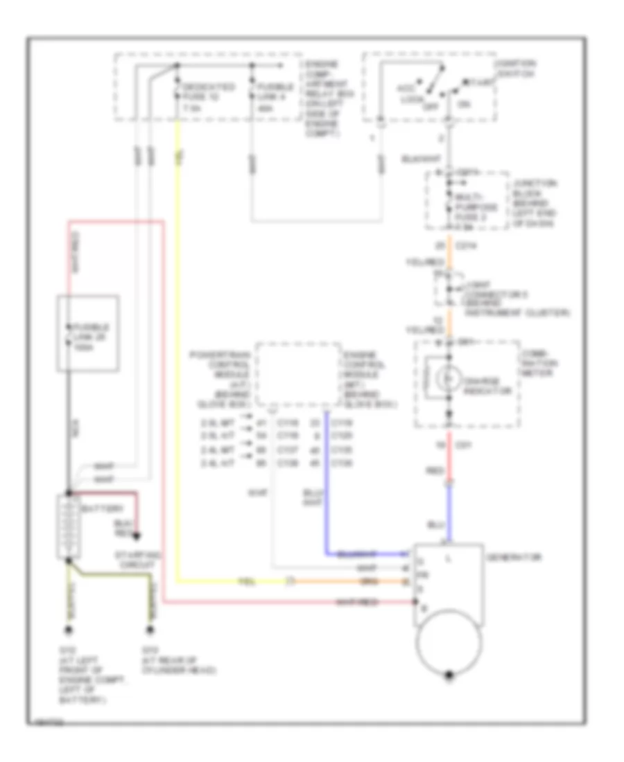
Charging Wiring Diagram, Evolution for Mitsubishi Lancer Evolution 2004
 https://portal-diagnostov.com/license.html
Automotive Electricians Portal FZCO
Automotive Electricians Portal FZCO
https://portal-diagnostov.com/license.html
https://portal-diagnostov.com/license.html
Automotive Electricians Portal FZCO
Automotive Electricians Portal FZCO
List of elements for Charging Wiring Diagram, Evolution for Mitsubishi Lancer Evolution 2004:
- 40a
- 7.5a
- Acc
- Battery
- C01
- C119
- C211
- C214
- Charge indicator
- Combination meter
- Dedicated fuse 12
- Engine comp- artment relay box (on left side of engine compt)
- Engine control module (behind glove box)
- Fuse 2 7.5a
- Fusible link 26 100a
- Fusible link 4
- G10 (at lower left rear of engine)
- G4 (left side of engine compartment)
- Generator
- Ignition switch
- Joint connector 4
- Junction block (behind left end of dash)
- Lock
- Nca
- Off
- Red
- Start
- Starting circuit
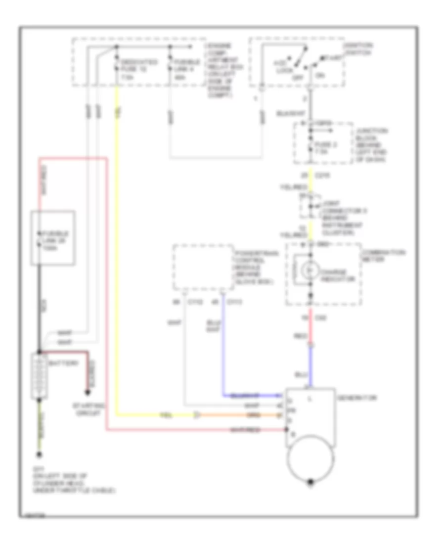
Charging Wiring Diagram, Except Wagon or Evolution for Mitsubishi Lancer Evolution 2004
List of elements for Charging Wiring Diagram, Except Wagon or Evolution for Mitsubishi Lancer Evolution 2004:
- 2.0l a/t
- 2.0l m/t
- 2.4l a/t
- 2.4l m/t
- 40a
- 7.5a
- Acc
- Battery
- C01
- C118
- C119
- C120
- C135
- C136
- C137
- C138
- C211
- C214
- Charge indicator
- Comb- ination meter
- Dedicated fuse 12
- Engine comp- artment relay box (on left side of engine compt)
- Engine control module (m/t) (behind glove box)
- Fusible link 26 100a
- Fusible link 4
- G10 (at rear of cylinder head)
- G12 (at left front of engine compt, left of battery)
- Generator
- Ignition switch
- Joint connector 5 (behind instrument cluster)
- Junction block (behind left end of dash)
- Lock
- Multi- purpose fuse 2 7.5a
- Nca
- Off
- Powertrain control module (a/t) (behind glove box)
- Red
- Start
- Starting circuit
Charging Wiring Diagram, Wagon for Mitsubishi Lancer Evolution 2004
List of elements for Charging Wiring Diagram, Wagon for Mitsubishi Lancer Evolution 2004:
- 40a
- 7.5a
- Acc lock
- Battery
- C02
- C112
- C113
- C212
- C215
- Charge indicator
- Combination meter
- Dedicated fuse 12
- Engine comp- artment relay box (on left side of engine compt)
- Fuse 2 7.5a
- Fusible link 26 100a
- Fusible link 4
- G11 (on left side of cylinder head, under throttle cable)
- Generator
- Ignition switch
- Joint connector 5 (behind instrument cluster)
- Junction block (behind left end of dash)
- Nca
- Off
- Powertrain control module (behind glove box)
- Red
- Start
- Starting circuit
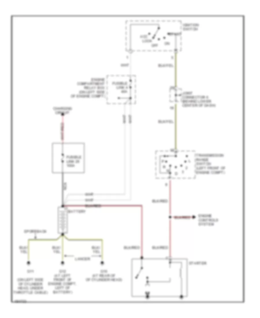
Starting Wiring Diagram, A/T for Mitsubishi Lancer Evolution 2004
List of elements for Starting Wiring Diagram, A/T for Mitsubishi Lancer Evolution 2004:
- (on left side of cylinder head, under throttle cable)
- Acc
- Battery
- Charging circuit
- Engine compartment relay box (on left side of engine compt)
- Engine controls system
- Fusible link 26 100a
- Fusible link 4 40a
- G10 (at rear of of cylinder head)
- G11
- G12 (at left front of engine compt, left of battery)
- Ignition switch
- Joint connector 6 (behind lower center of dash)
- Lancer
- Lock
- Nca
- Off
- Sportback
- Start
- Starter
- Transmission range switch (left front of engine compt)
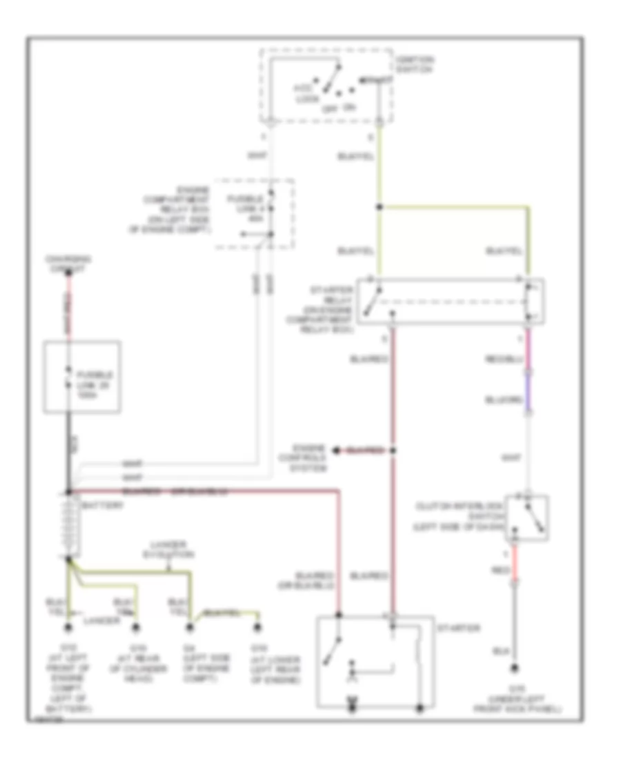
Starting Wiring Diagram, M/T for Mitsubishi Lancer Evolution 2004
List of elements for Starting Wiring Diagram, M/T for Mitsubishi Lancer Evolution 2004:
- (at lower left rear of engine)
- Acc
- Battery
- Charging circuit
- Clutch interlock switch (left side of dash)
- Engine compartment relay box (on left side of engine compt)
- Engine controls system
- Fusible link 26 100a
- Fusible link 4 40a
- G10
- G10 (at rear of cylinder head)
- G12 (at left front of engine compt, left of battery)
- G15 (under left front kick panel)
- G4 (left side of engine compt)
- Ignition switch
- Lancer
- Lancer evolution
- Lock
- Nca
- Off
- Red
- Start
- Starter
- Starter relay (on engine compartment relay box)

 Čeština
 Dansk
Dansk Ελληνικά
 English
 English
 Español
 Suomi
Suomi Français
 Français
 עברית
עברית Hrvatski
 Magyar
 Italiano
 日本語
日本語 한국어
한국어 Nederlands
 Polski
 Português
 Português
 Română
 Русский
 Slovenčina
 Slovenščina
 Svenska
 Türkçe
 中文 (中国)