
 Čeština
 Dansk
Dansk Ελληνικά
 English
 English
 Español
 Suomi
Suomi Français
 Français
 עברית
עברית Hrvatski
 Magyar
 Italiano
 日本語
日本語 한국어
한국어 Nederlands
 Polski
 Português
 Português
 Română
 Русский
 Slovenčina
 Slovenščina
 Svenska
 Türkçe
 中文 (中国)

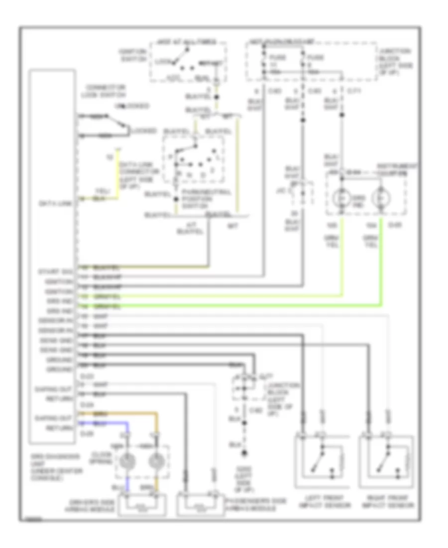
SUPPLEMENTAL RESTRAINTS
Supplemental Restraint Wiring Diagram for Mitsubishi 3000GT VR-4 1995
List of elements for Supplemental Restraint Wiring Diagram for Mitsubishi 3000GT VR-4 1995:

ACTIVE AERODYNAMICSANTI-LOCK BRAKESANTI-THEFTCOMPUTER DATA LINESBODY COMPUTERCOOLING FANAIR CONDITIONINGDEFOGGERSCRUISE CONTROLEXTERIOR LIGHTSGROUND DISTRIBUTIONENGINE PERFORMANCEPASSIVE RESTRAINTSINSTRUMENT CLUSTERELECTRONIC SUSPENSIONHEADLIGHTSHORNINTERIOR LIGHTSPOWER ANTENNAPOWER WINDOWSPOWER DISTRIBUTIONPOWER MIRRORSPOWER TOP/SUNROOFSTARTING/CHARGINGPOWER SEATSSUPPLEMENTAL RESTRAINTSWARNING SYSTEMSRADIOWIPER/WASHER