
 Čeština
 Dansk
Dansk Ελληνικά
 English
 English
 Español
 Suomi
Suomi Français
 Français
 עברית
עברית Hrvatski
 Magyar
 Italiano
 日本語
日本語 한국어
한국어 Nederlands
 Polski
 Português
 Português
 Română
 Русский
 Slovenčina
 Slovenščina
 Svenska
 Türkçe
 中文 (中国)

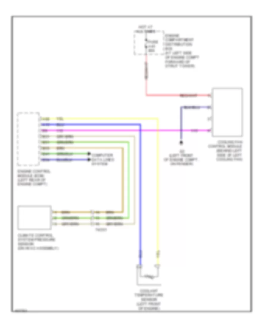
COOLING FAN
Cooling Fan Wiring Diagram for Volvo XC70 2013
List of elements for Cooling Fan Wiring Diagram for Volvo XC70 2013:

AIR CONDITIONINGANTI-LOCK BRAKESANTI-THEFTCOOLING FANCRUISE CONTROLCOMPUTER DATA LINESDEFOGGERSELECTRONIC SUSPENSIONHORNENGINE PERFORMANCEGROUND DISTRIBUTIONEXTERIOR LIGHTSHEADLIGHTSINTERIOR LIGHTSNAVIGATIONMEMORY SYSTEMSPOWER DOOR LOCKSPOWER DISTRIBUTIONINSTRUMENT CLUSTERPOWER MIRRORSPOWER SEATSPOWER TOP/SUNROOFSUPPLEMENTAL RESTRAINTSSTARTING/CHARGINGPOWER WINDOWSSHIFT INTERLOCKTRANSMISSIONRADIOTRUNK, TAILGATE, FUEL DOORWARNING SYSTEMSWIPER/WASHERBODY CONTROL MODULESELECTRONIC POWER STEERING