
 Čeština
 Dansk
Dansk Ελληνικά
 English
 English
 Español
 Suomi
Suomi Français
 Français
 עברית
עברית Hrvatski
 Magyar
 Italiano
 日本語
日本語 한국어
한국어 Nederlands
 Polski
 Português
 Português
 Română
 Русский
 Slovenčina
 Slovenščina
 Svenska
 Türkçe
 中文 (中国)

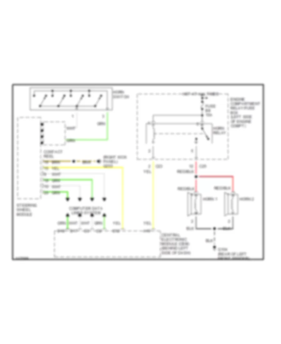
HORN
Horn Wiring Diagram for Volvo V70 XC 2001
List of elements for Horn Wiring Diagram for Volvo V70 XC 2001:

AIR CONDITIONINGBODY COMPUTERANTI-THEFTCOMPUTER DATA LINESDEFOGGERSCRUISE CONTROLCOOLING FANELECTRONIC POWER STEERINGEXTERIOR LIGHTSINSTRUMENT CLUSTERHORNENGINE PERFORMANCEINTERIOR LIGHTSPOWER DISTRIBUTIONHEADLIGHTSMEMORY SYSTEMSGROUND DISTRIBUTIONPOWER DOOR LOCKSNAVIGATIONPOWER WINDOWSPOWER TOP/SUNROOFPOWER SEATSPOWER MIRRORSRADIOSUPPLEMENTAL RESTRAINTSSHIFT INTERLOCKSSTARTING/CHARGINGTRANSMISSIONWARNING SYSTEMSWIPER/WASHERANTI-LOCK BRAKES