ANTI-THEFT
Anti-theft Alarm Wiring Diagram for Volvo V70 XC 2001

List of elements for Anti-theft Alarm Wiring Diagram for Volvo V70 XC 2001:
- A/c system
- A11
- A12
- A13
- A14
- A15
- A16
- Alarm siren (at right front corner of vehicle)
- Alarm/ electronic immobilizer indicator (top center of dash)
- B12
- B17
- B18
- C18
- Cargo compartment fuse box (at left side of trunk)
- Central electronic module (behind left side of dash, on passenger compartment relay box)
- Climate control module (behind center of dash)
- Computer data lines system
- D20
- Exterior lights system
- Fuse c38 5a
- Fuse d10 10a
- G102 (left front shock tower)
- G105 (rear of right front fender)
- G309 (left front door sill)
- G315 (rear of right rear door sill)
- G316 (right front door sill)
- G317 (rear of left rear door sill)
- G908 (center front of roof)
- Hood alarm switch (left front corner of engine compt)
- Hot at all times
- Instrument cluster
- Key
- Left front door control module (inside left front door)
- Left front door lock unit
- Left glass breakage wire (v70 optional)
- Left rear door lock unit
- Microwave sensor alarm (at rear of sun roof opening)
- Nca
- Pager alarm (optional)
- Pager alarm relay 1 (optional)
- Pager alarm relay 2 (optional)
- Passenger compartment fuse box (at left end of dash)
- Pnk
- Rear electronic module (left side of trunk, on cargo compt relay/fuse box)
- Red
- Right front door control module (inside right front door)
- Right front door lock unit
- Right glass breakage wire (v70 optional)
- Right rear door lock unit
- Switch reduced alarm
- Trunk lid lock unit (inside trunk door)
- Trunk lid/ tailgate glass breakage wire (v70 optional)
- Ulk
- Upper electronic module (above center of windshield on rear- view mirror)
- Vehicle inclination sensor (at left rear side of trunk)
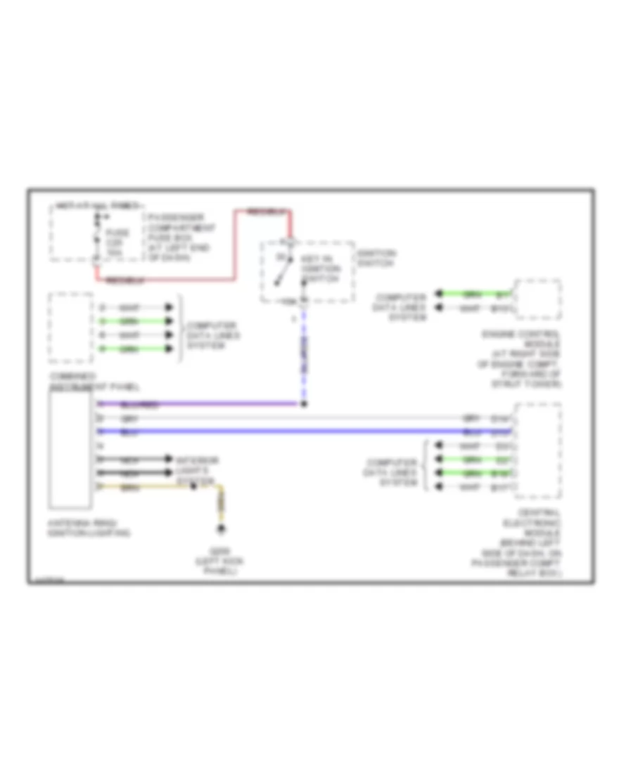
Immobilizer Wiring Diagram for Volvo V70 XC 2001
List of elements for Immobilizer Wiring Diagram for Volvo V70 XC 2001:
- 15a
- Antenna ring/ ignition lighting
- B13
- B17
- B18
- Central electronic module (behind left side of dash, on passenger compt relay box)
- Combined instrument panel
- Computer data lines system
- D13
- D14
- Engine control module (at right side of engine compt, forward of strut tower)
- Fuse c25 10a
- G200 (left kick panel)
- Hot at all times
- Ignition switch
- Interior lights system
- Key in ignition switch
- Nca
- Passenger compartment fuse box (at left end of dash)