TRANSMISSION
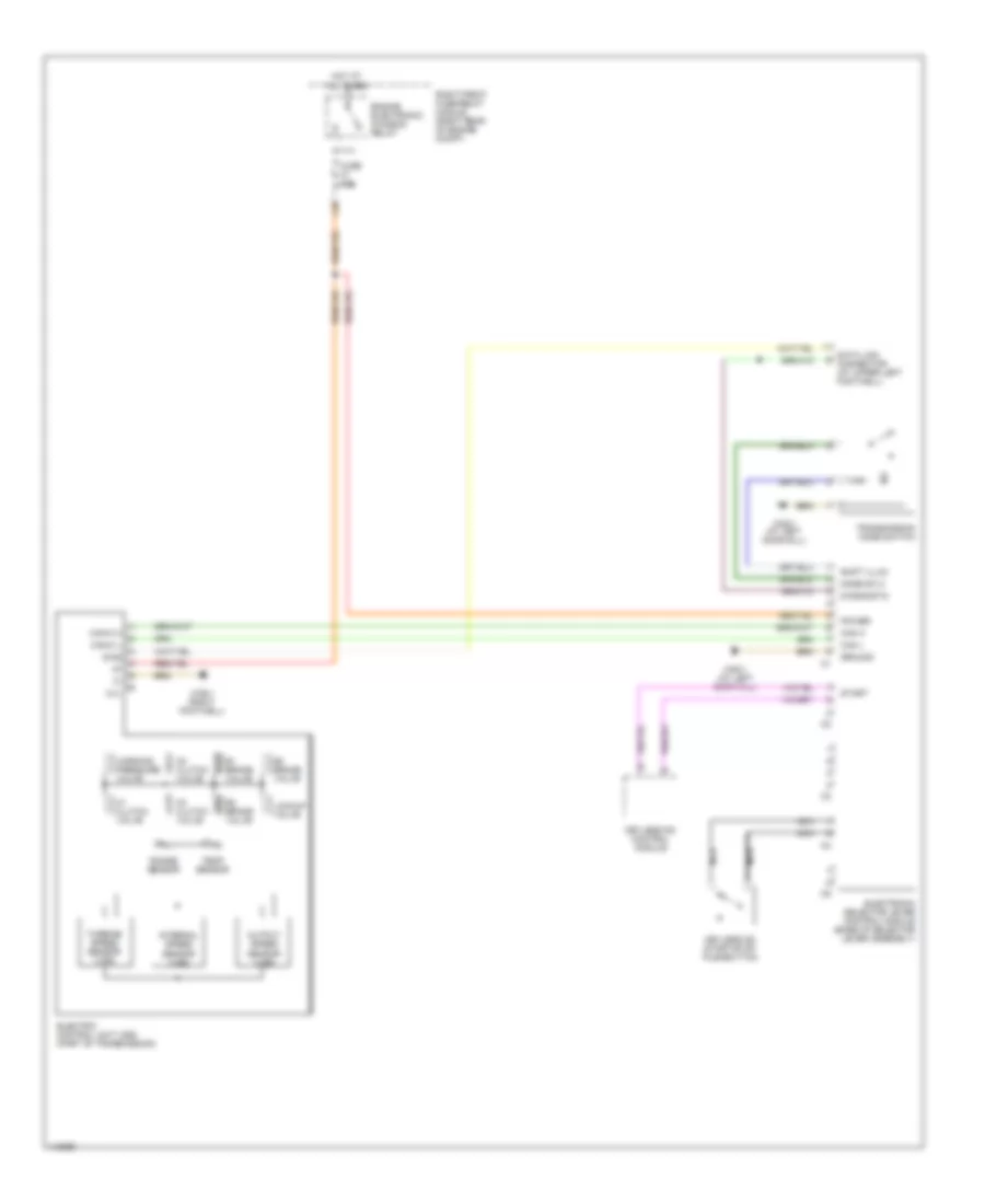
A/T Wiring Diagram, 5 Speed for Mercedes-Benz S500 2005
 https://portal-diagnostov.com/license.html
Automotive Electricians Portal FZCO
Automotive Electricians Portal FZCO
https://portal-diagnostov.com/license.html
https://portal-diagnostov.com/license.html
Automotive Electricians Portal FZCO
Automotive Electricians Portal FZCO
List of elements for A/T Wiring Diagram, 5 Speed for Mercedes-Benz S500 2005:
- 1-2/ 4-5 valve
- 1-2/4-5 vlv
- 2-3 shift valve
- 2-3 vlv
- 3-4 shift valve
- 3-4 vlv
- Can (+)
- Can (-)
- Can h
- Can l
- Computer data lines system
- Data line
- Data link connector (at upper left footwell)
- Diagnostic
- Electronic selector lever control module (base of selector lever assembly)
- Engine electronic/ chassis relay
- Etc control module (right rear of engine compt)
- Fuse 15a
- Ground
- Hot at all times
- Keyless go control module
- Keyless go start/stop pushbutton
- L18
- Lock up valve
- Mode sw 2
- Modul- ator valve
- Modulator vlv
- Nca
- Power
- Pwm vlv
- Right front fuse/relay module (right rear of engine compt)
- Rpm 2
- Rpm 3
- Rpm sensor
- Sensor ground
- Sensor v+
- Shift illum
- Shift valve
- Shift vlv
- Start
- Start interlock switch
- Temp sensor
- Temp/start
- Transmission mode switch
- Valve unit (electronic transmission control)
- W28/1 (at left door sill)
- W36/1 (right footwell)
A/T Wiring Diagram, 7 Speed for Mercedes-Benz S500 2005
List of elements for A/T Wiring Diagram, 7 Speed for Mercedes-Benz S500 2005:
- B1 brake valve
- B2 brake valve
- B3 brake valve
- Can h
- Can l
- Can-c h
- Can-c l
- Data link connector (at upper left footwell)
- Diag
- Diagnostic
- Electric control unit (vgs) (part of transmission)
- Electronic selector lever control module (base of selector lever assembly)
- Engine electronic/ chassis relay
- Fuse 15a
- Ground
- Hot at all times
- Internal speed sensor (vgs)
- K1 clutch valve
- K2 clutch valve
- K3 clutch valve
- Keyless go control module
- Keyless go start/stop pushbutton
- L18
- Lockup valve
- Mode sw 2
- N.c.
- Nca
- Output speed sensor (vgs)
- Power
- Range sensor
- Right front fuse/relay module (right rear of engine compt)
- Shift illum
- Start
- Temp sensor
- Transmission mode switch
- Turbine speed sensor (vgs)
- W28/1 (at left door sill)
- W36/1 (right footwell)
- Working pressure valve

 Čeština
 Dansk
Dansk Ελληνικά
 English
 English
 Español
 Suomi
Suomi Français
 Français
 עברית
עברית Hrvatski
 Magyar
 Italiano
 日本語
日本語 한국어
한국어 Nederlands
 Polski
 Português
 Português
 Română
 Русский
 Slovenčina
 Slovenščina
 Svenska
 Türkçe
 中文 (中国)