WARNING SYSTEMS
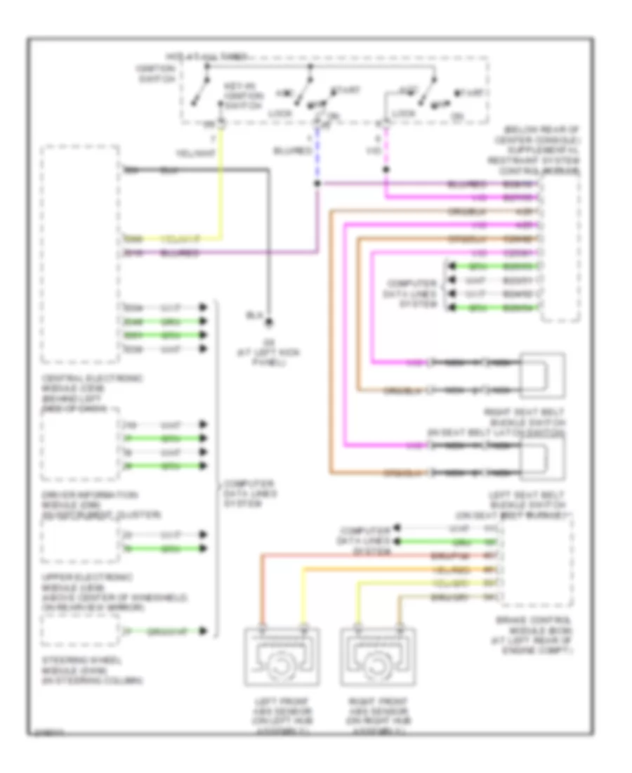
Warning Systems Wiring Diagram for Volvo S80 2005
List of elements for Warning Systems Wiring Diagram for Volvo S80 2005:
- A25
- A26
- Acc
- B23/51
- B24/52
- B25/53
- B26/54
- B27/55
- B28/56
- Brake control module (bcm) (at left rear of engine compt)
- C25/81
- C26/82
- Central electronic module (cem) (behind left side of dash)
- Computer data lines system
- D16
- D34
- D36
- D49
- D51
- D60
- Driver information module (dim) (in instrument cluster)
- G6 (at left kick panel)
- Hot at all times
- Ignition switch
- Key-in ignition switch
- Left front abs sensor (on left hub assembly)
- Left seat belt buckle switch (on seat belt buckle)
- Lock
- Nca
- Off
- Right front abs sensor (on right hub assembly)
- Right seat belt buckle switch (in seat belt latch switch)
- Start
- Steering wheel module (swm) (in steering column)
- Upper electronic module (uem) (above center of windshield, on rearview mirror)
 Čeština
 Dansk
Dansk Ελληνικά
 English
 English
 Español
 Suomi
Suomi Français
 Français
 עברית
עברית Hrvatski
 Magyar
 Italiano
 日本語
日本語 한국어
한국어 Nederlands
 Polski
 Português
 Português
 Română
 Русский
 Slovenčina
 Slovenščina
 Svenska
 Türkçe
 中文 (中国)
 Deutsch