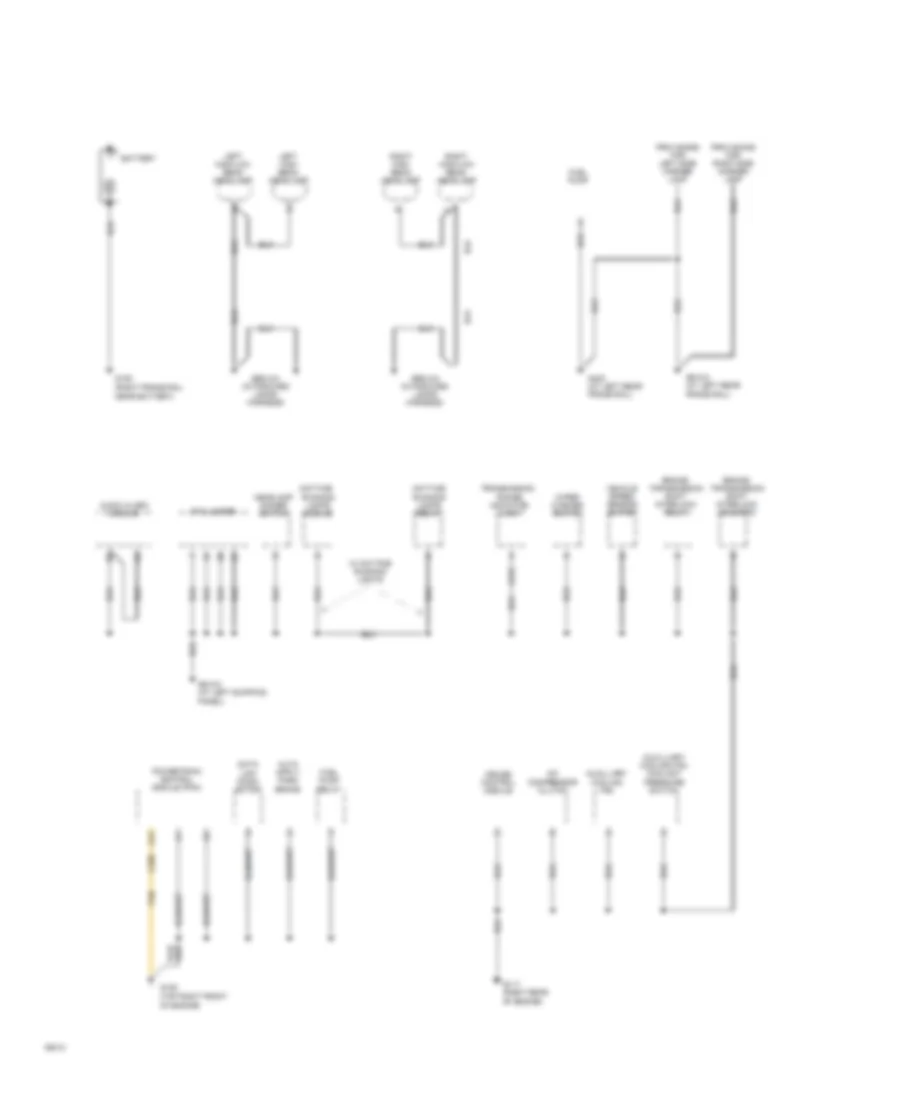
ANTI-LOCK BRAKES
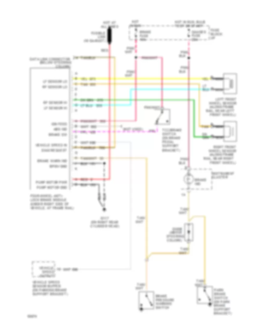
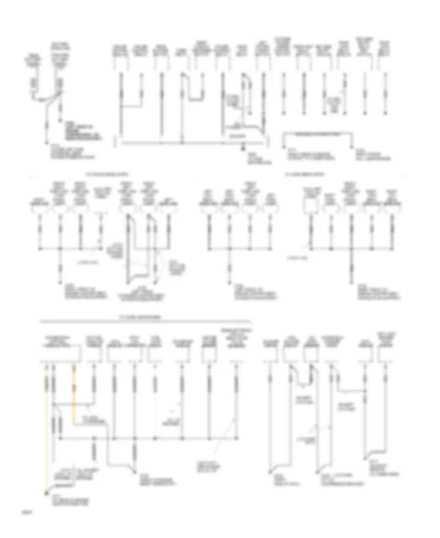
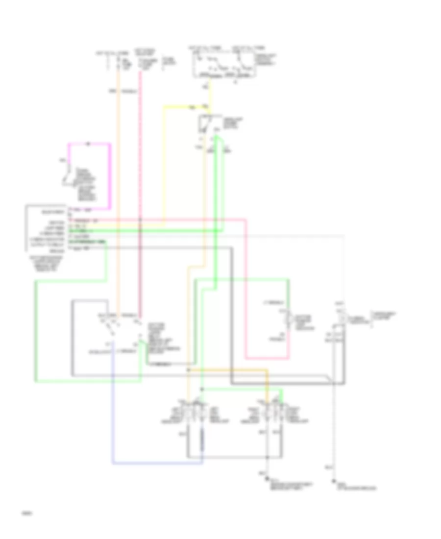
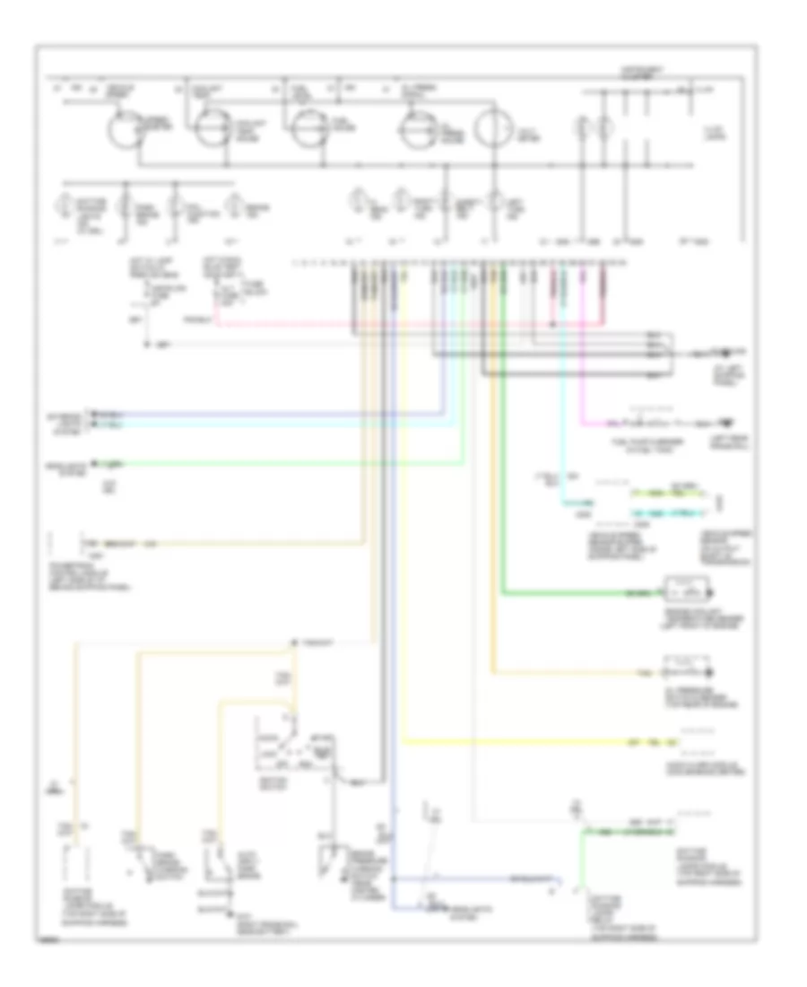
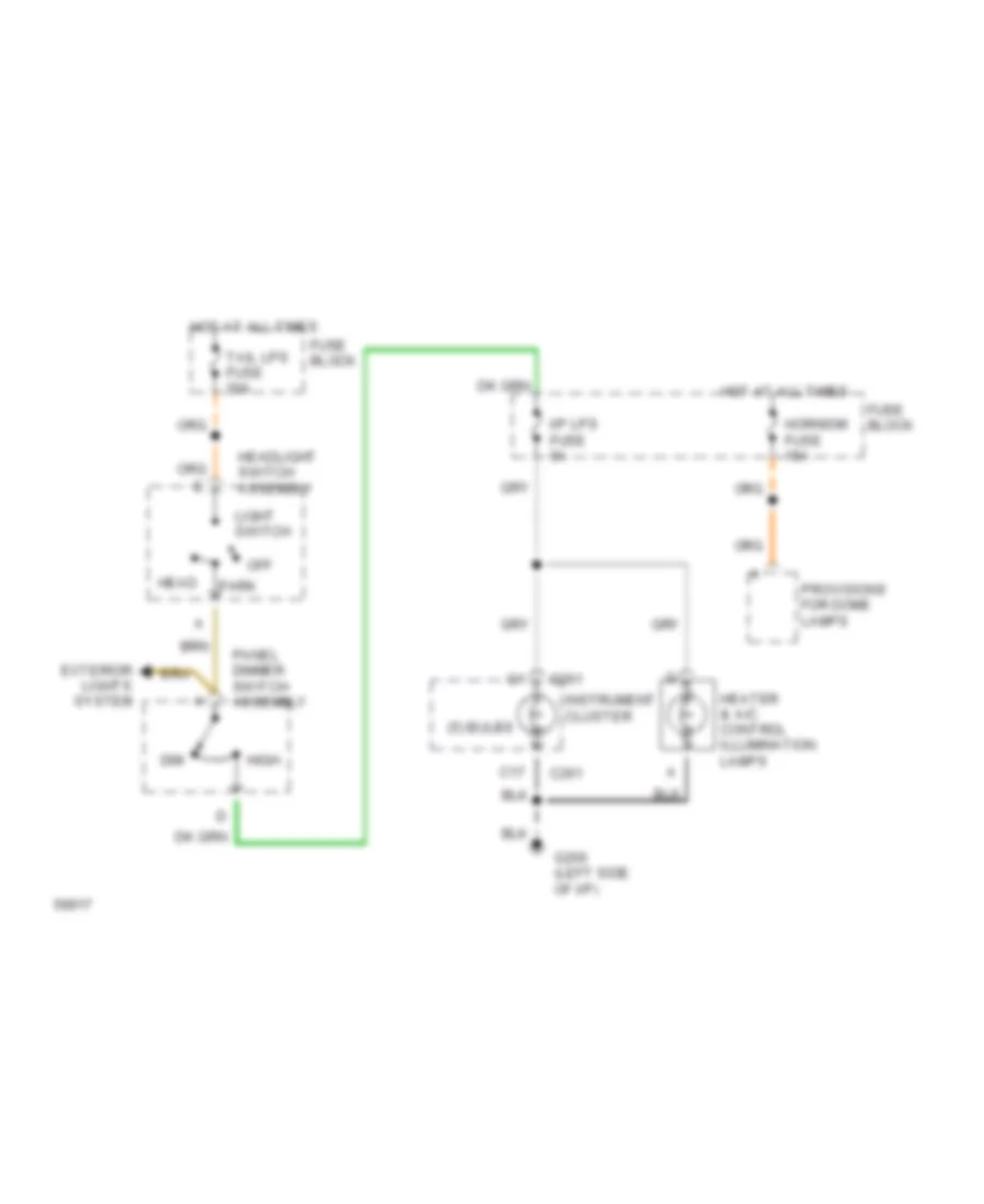
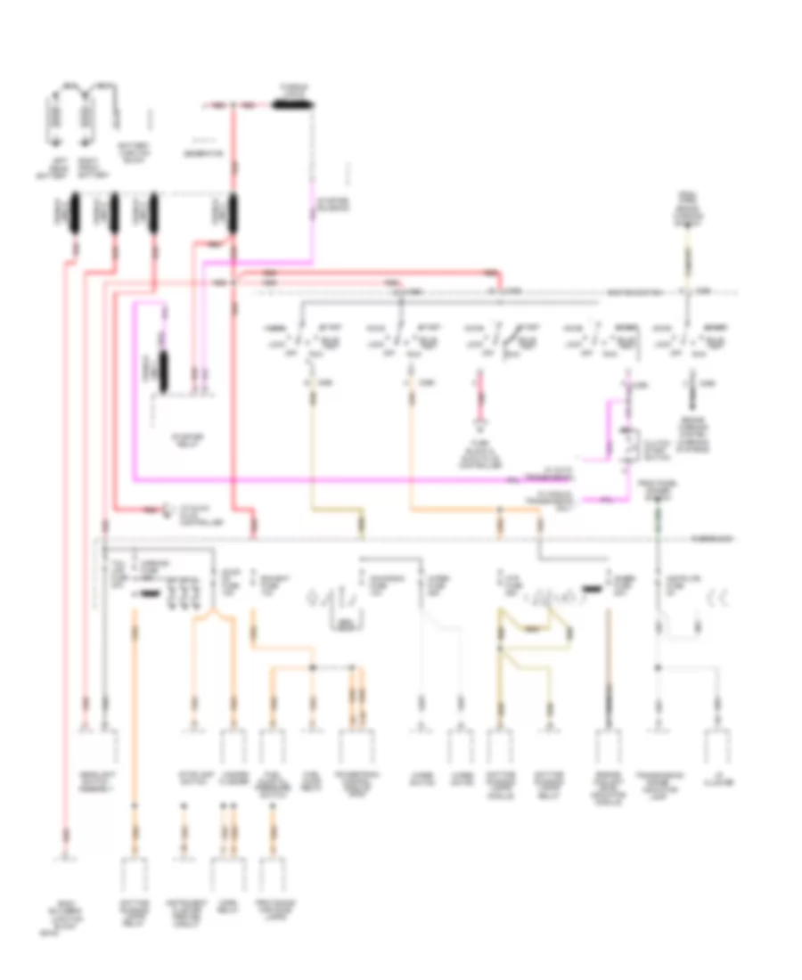
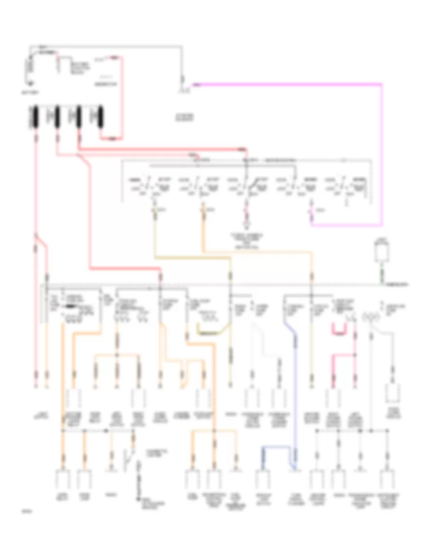
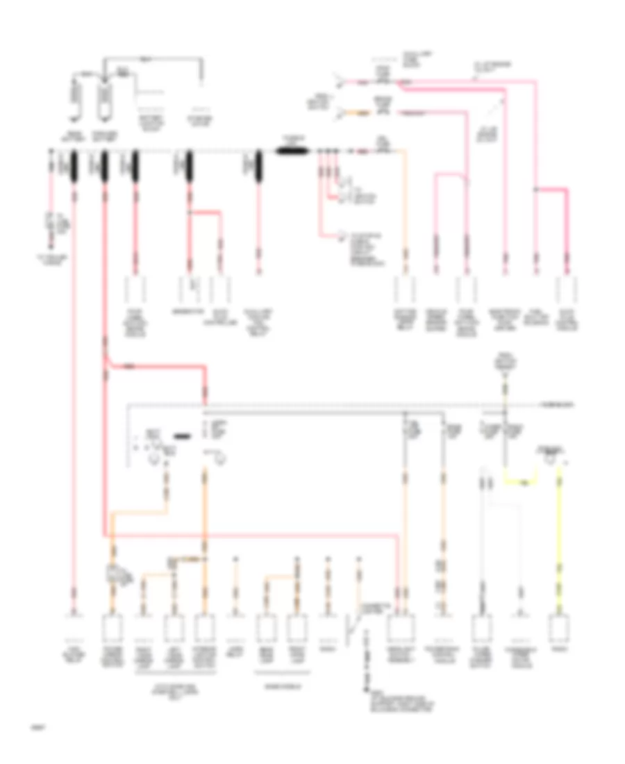
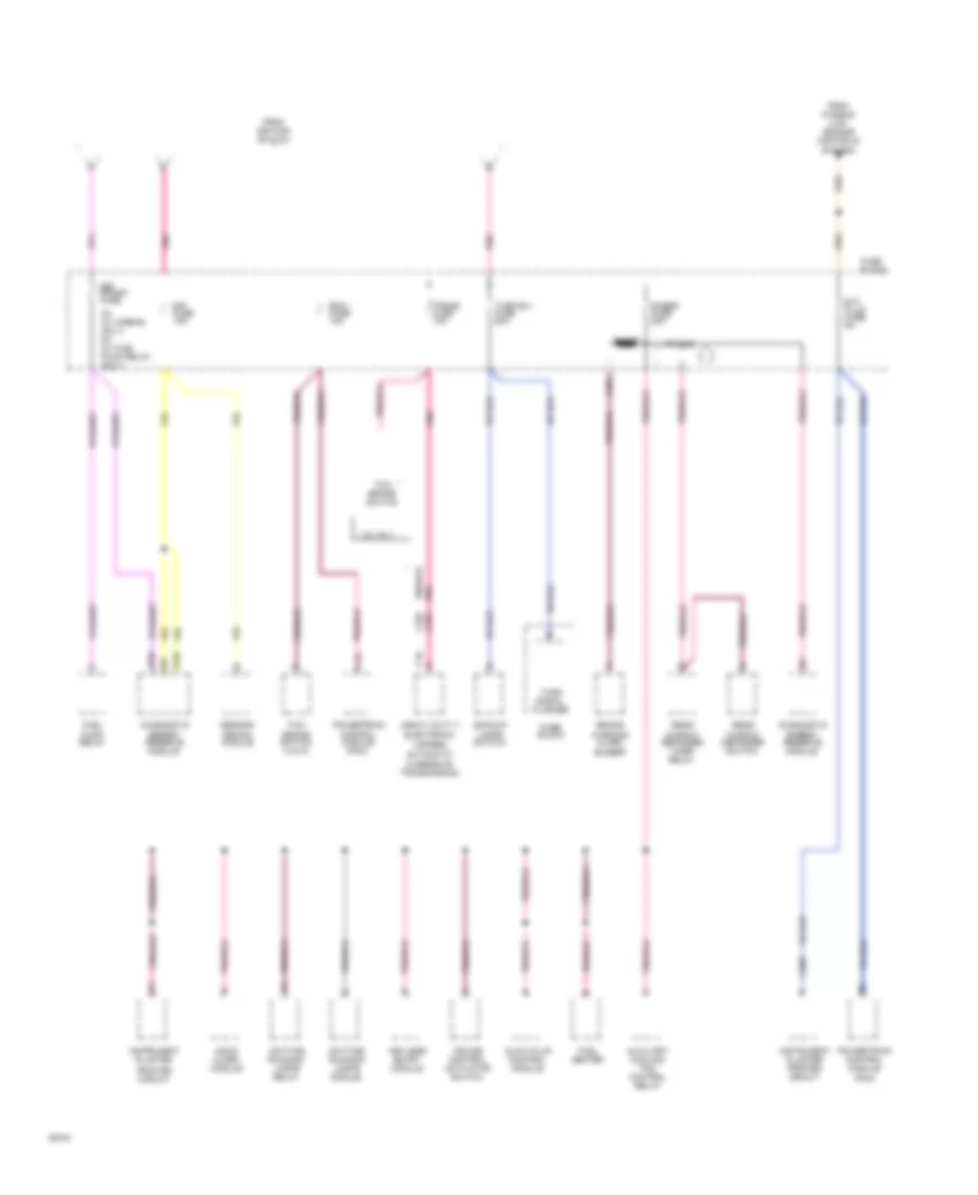
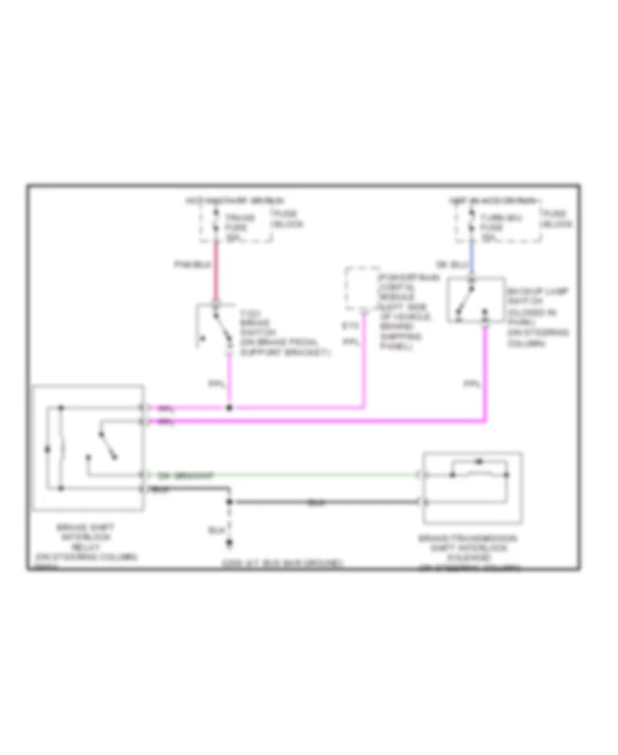
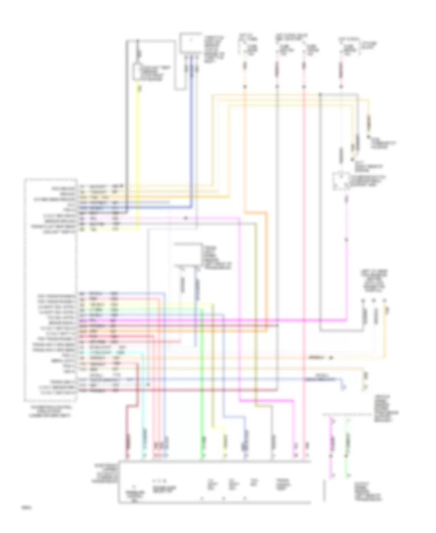
All-Wheel ABS Wiring Diagram, with DRL for GMC Vandura G1994 2500
 https://portal-diagnostov.com/license.html
Automotive Electricians Portal FZCO
Automotive Electricians Portal FZCO
https://portal-diagnostov.com/license.html
https://portal-diagnostov.com/license.html
Automotive Electricians Portal FZCO
Automotive Electricians Portal FZCO
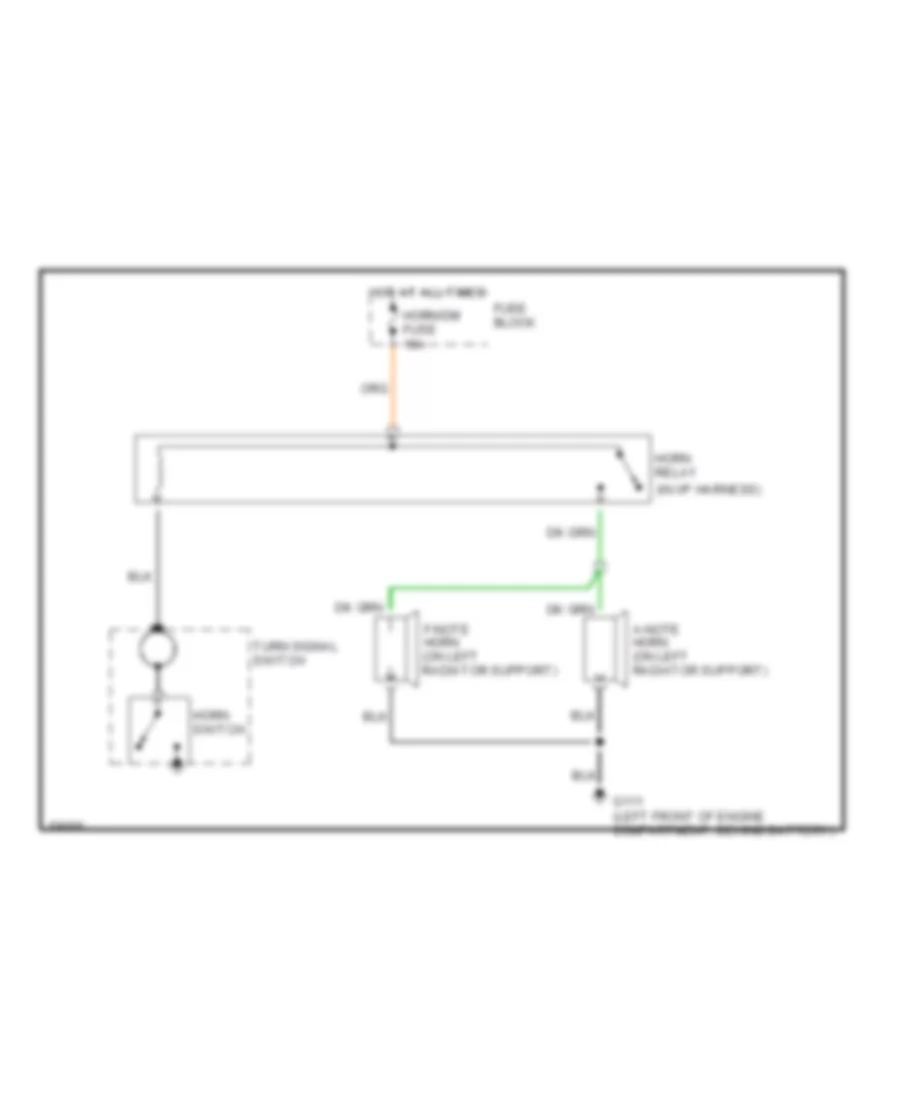
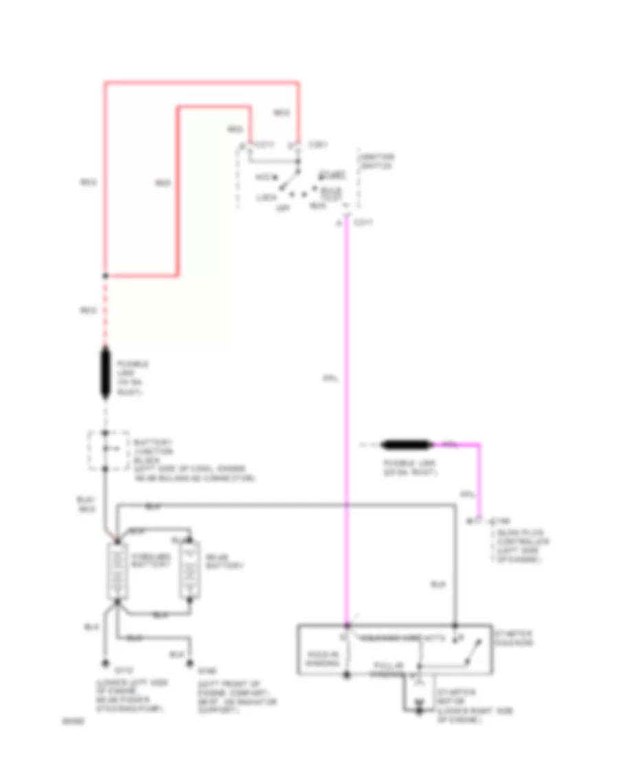
List of elements for All-Wheel ABS Wiring Diagram, with DRL for GMC Vandura G1994 2500:
- (along frame
- (below steering
- (not used)
- (on right rear cylinder head)
- Abs ind
- B tan
- Bpmv gnd
- Bracket)
- Brake fuse 10a
- Brake ind.
- Brake pressure warning switch
- Brake sw
- Brake warn ind
- Cluster
- Column)
- Data link connector
- Daytime running lamps module (left side of i/p)
- Diag request
- Diode array module (under left side of i/p)
- Four-wheel anti- lock brake module (under right side of vehicle, at frame rail)
- Front wheel)
- Fuse block: i/p
- Fusible link (16 ga-rust)
- G117
- Gauges fuse 20a
- Hot at all times
- Hot in run
- Hot in run, bulb test or start
- Ign feed
- Ignition switch
- Instrument
- Left front wheel sensor
- Lf sensor hi
- Lf sensor lo
- Nca
- Output
- Park brake switch
- Pnk/
- Pump motor gnd
- Pump motor pwr
- Rail, near left
- Rail, near right
- Red
- Rf sensor hi
- Rf sensor lo
- Right front wheel sensor
- Speed
- Tan
- Tan/
- Tcc/brake switch (on brake pedal support
- Vehicle
- Vehicle speed in
- Vehicle speed sensor buffer (on parking brake support bracket)
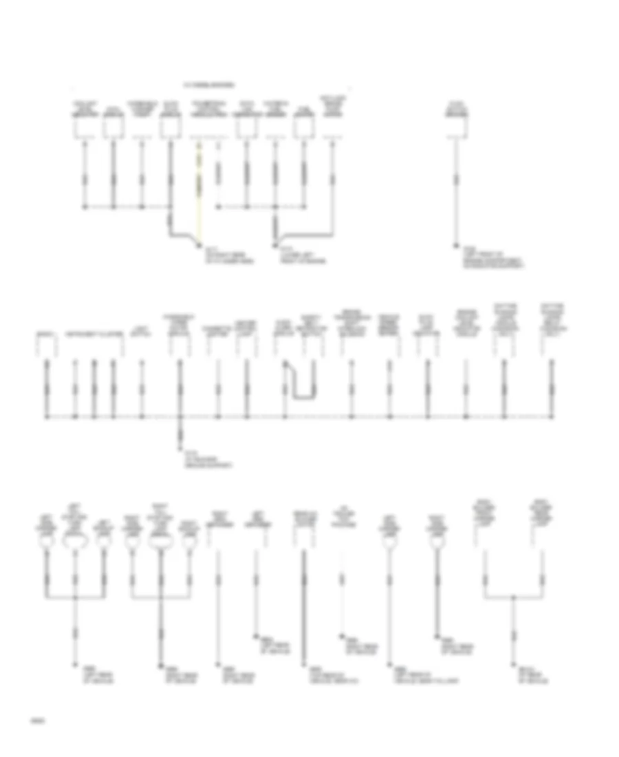
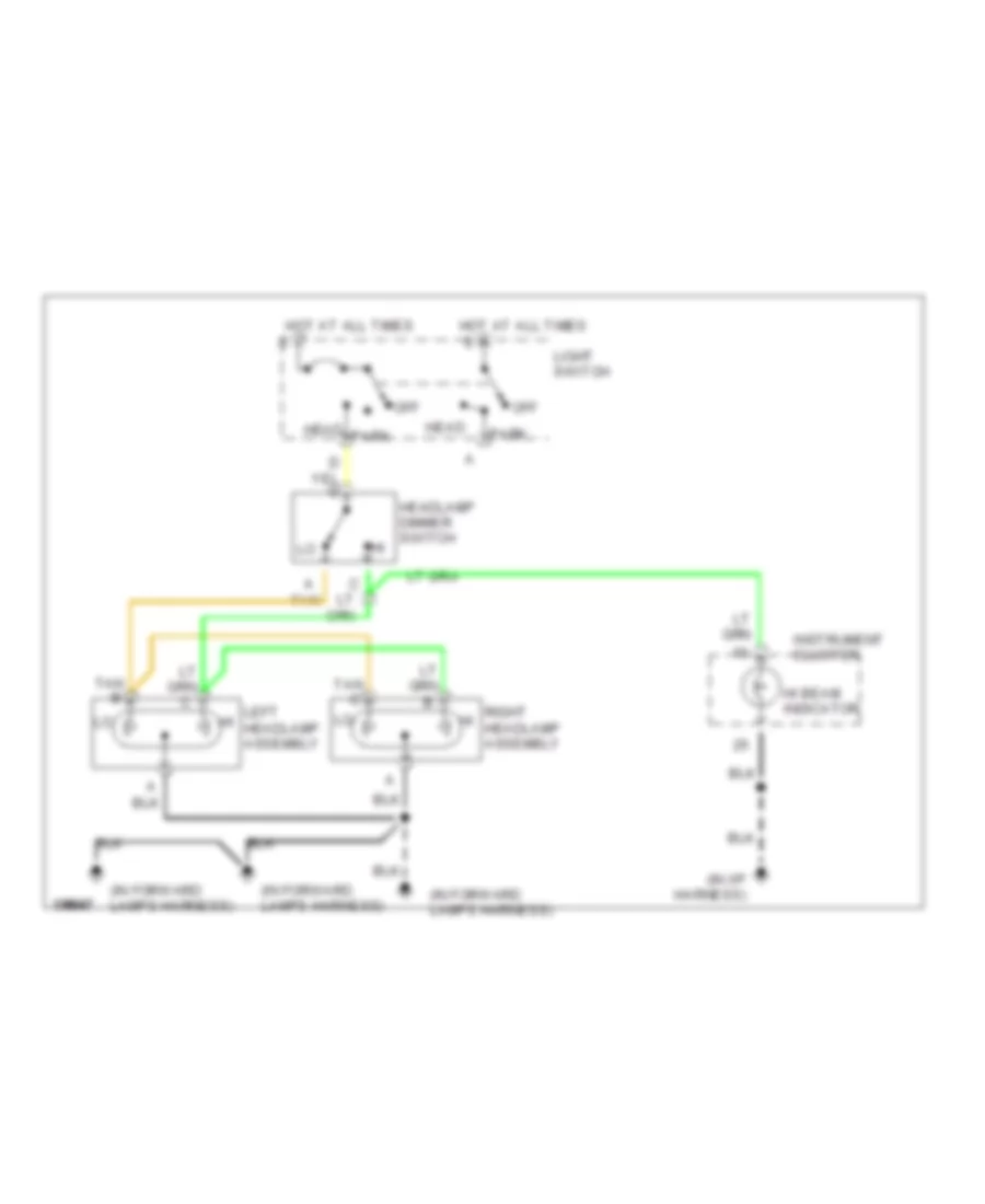
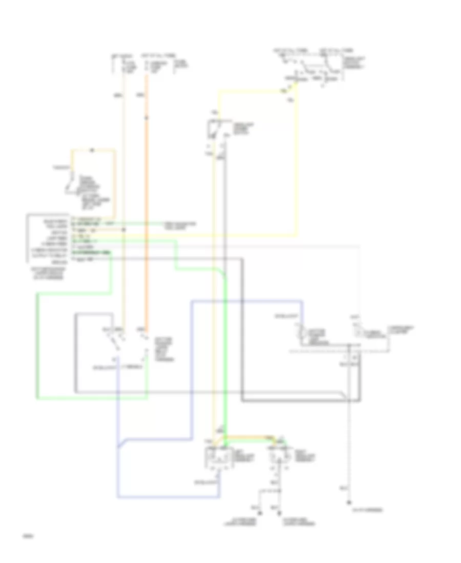
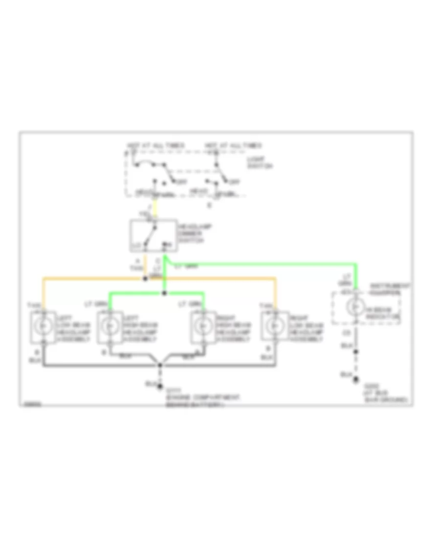
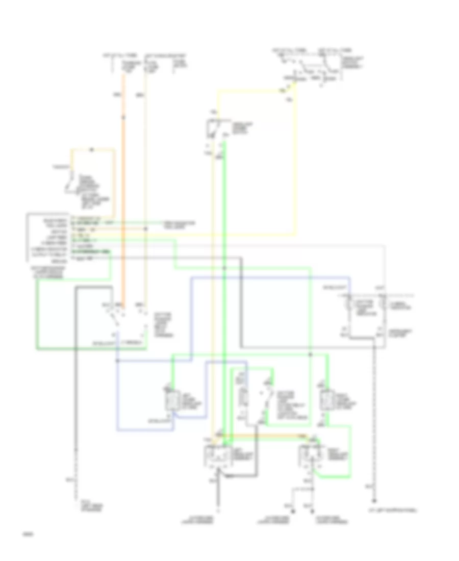
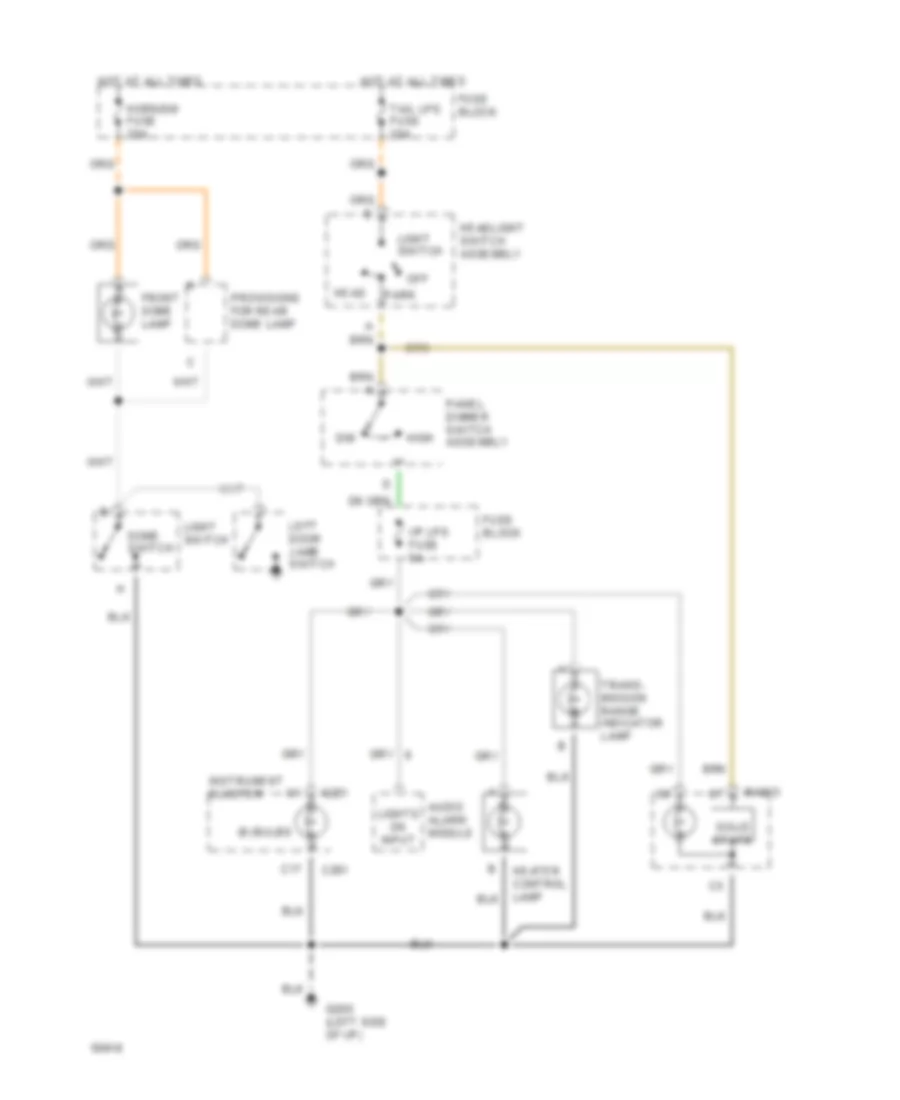
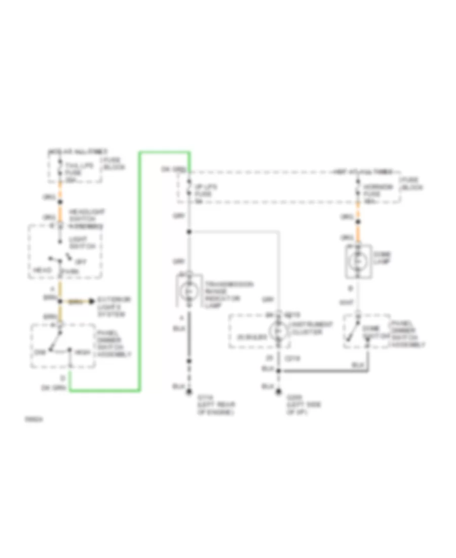
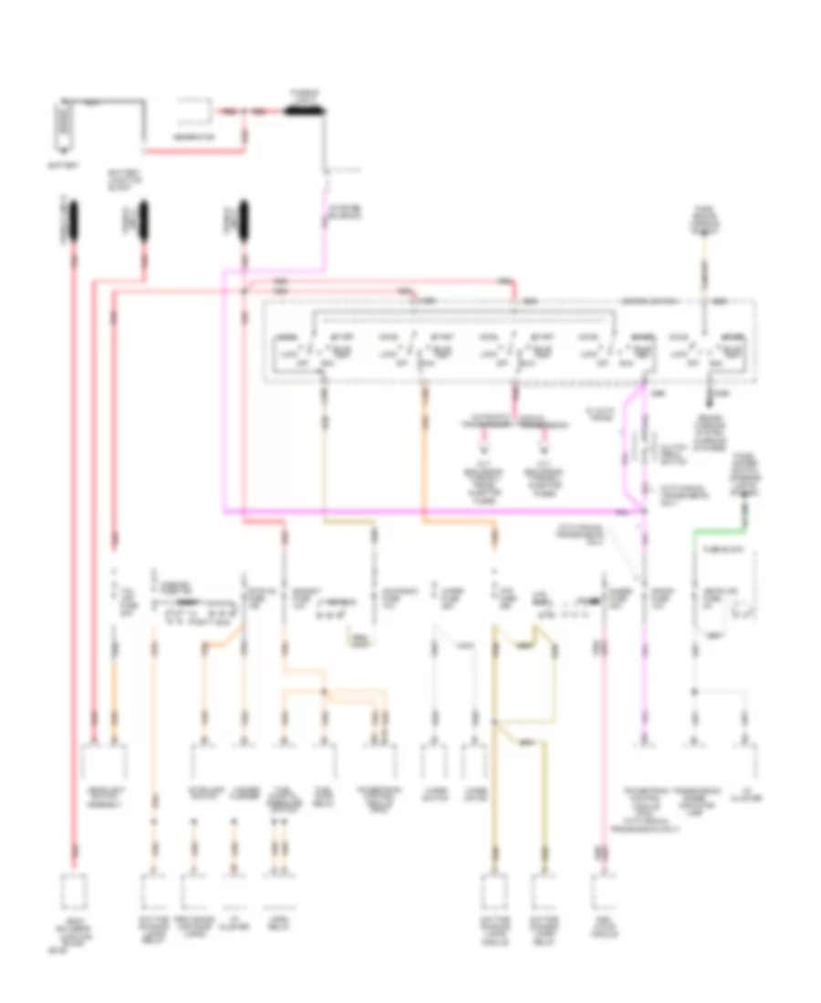
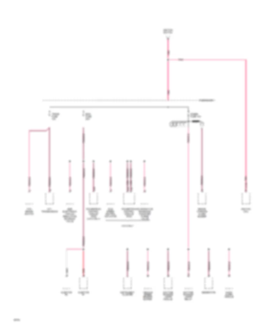
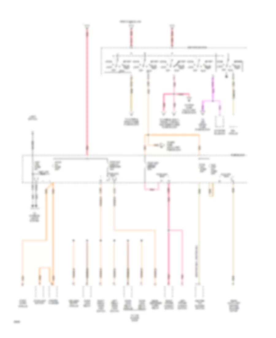
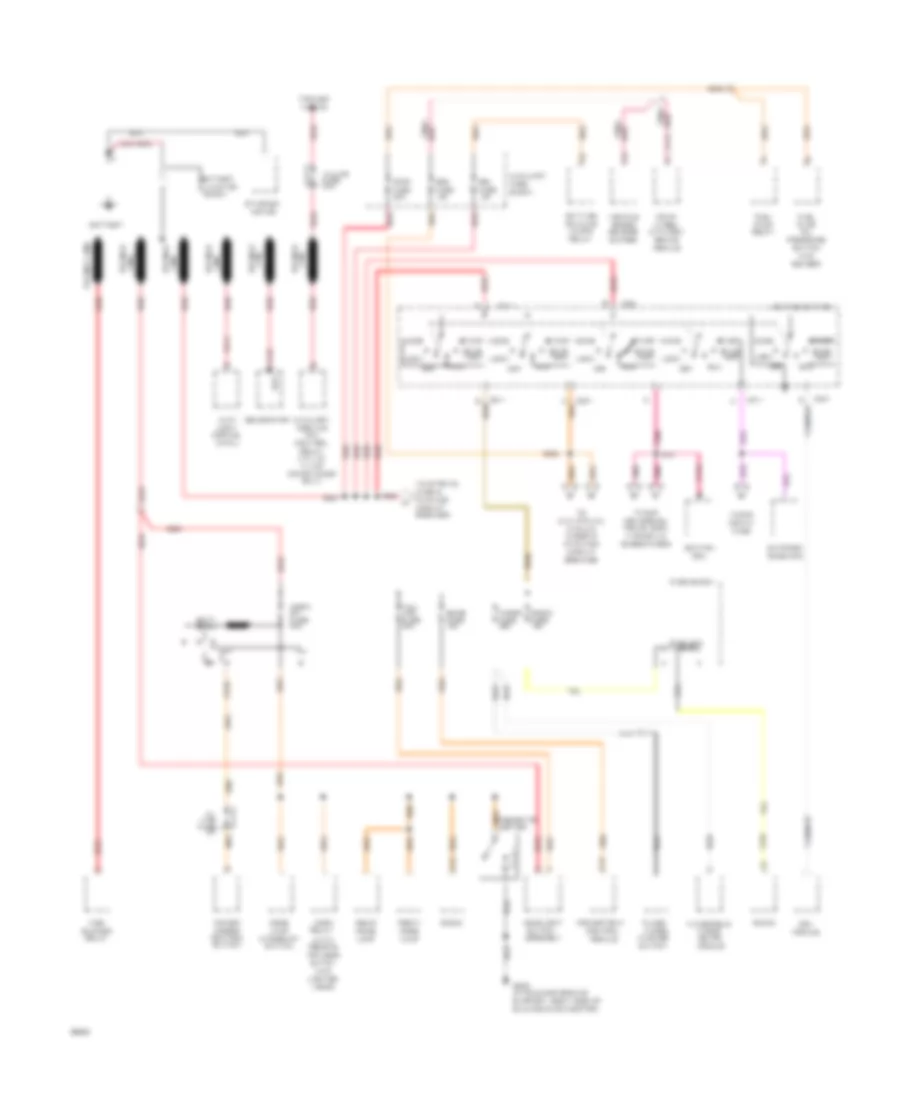
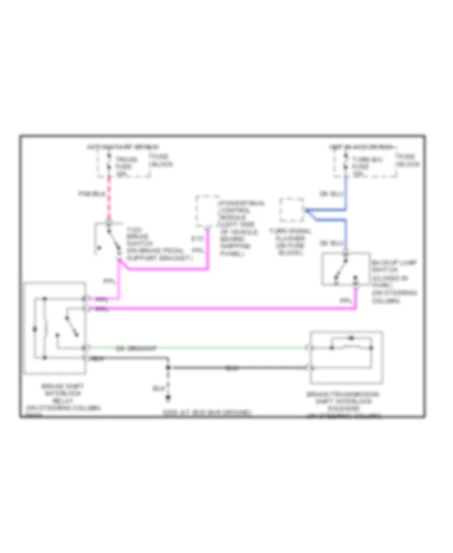
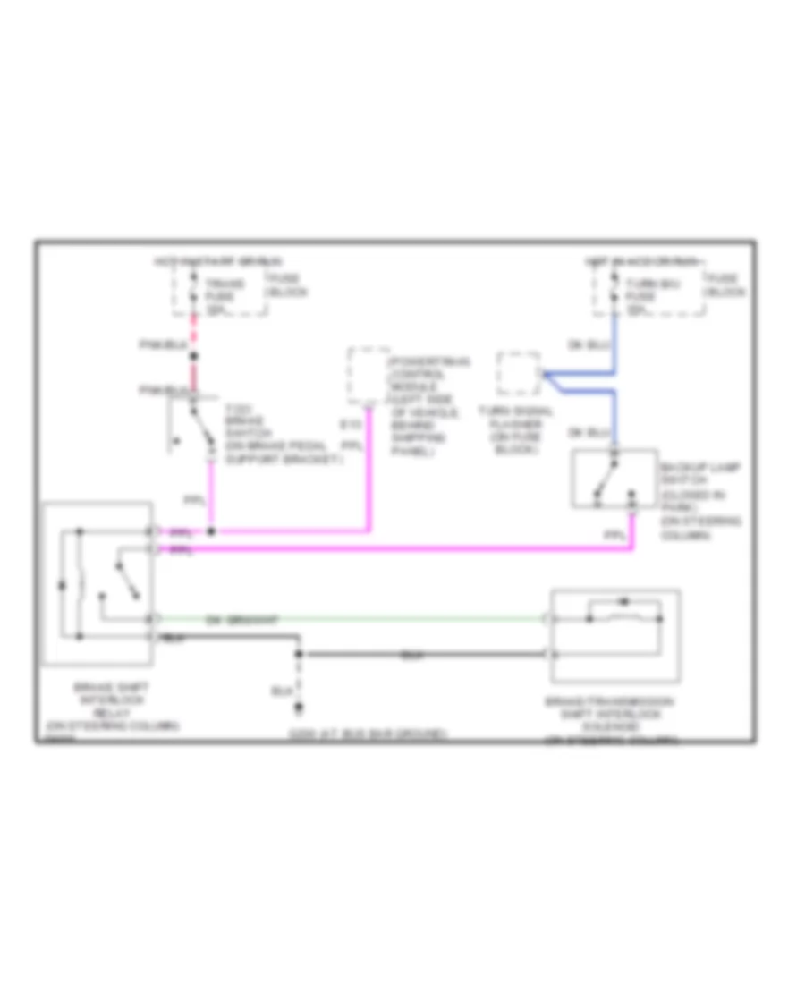
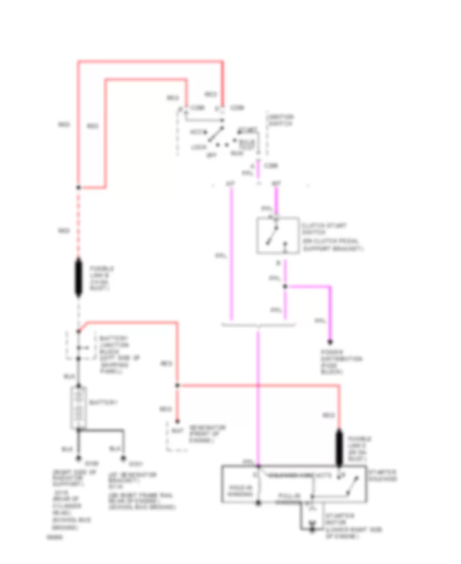
All-Wheel ABS Wiring Diagram, without DRL for GMC Vandura G1994 2500
List of elements for All-Wheel ABS Wiring Diagram, without DRL for GMC Vandura G1994 2500:
- (above
- (along frame
- (below steering
- (not used)
- Abs ind
- B tan
- Bpmv gnd
- Bracket)
- Brake fuse 10a
- Brake ind.
- Brake pressure warning switch
- Brake sw
- Brake warn ind
- Cluster
- Column)
- Data link connector
- Diag request
- Diode
- Four-wheel anti- lock brake module (under right side of vehicle, at frame rail)
- Front wheel)
- Fuse block: i/p
- Fusible link (16 ga-rust)
- G117 (on right rear cylinder head)
- Gauges fuse 20a
- Hot at all times
- Hot in run
- Hot in run, bulb test or start
- Ign feed
- Instrument
- Left front wheel sensor
- Lf sensor hi
- Lf sensor lo
- Nca
- Output
- Park brake switch (on park brake support bracket)
- Pnk/
- Pump motor gnd
- Pump motor pwr
- Rail, near left
- Rail, near right
- Red
- Rf sensor hi
- Rf sensor lo
- Right front wheel sensor
- Speed
- Steering column)
- Tan
- Tcc/brake switch (on brake pedal support
- Vehicle
- Vehicle speed in
- Vehicle speed sensor buffer (on parking brake support bracket)
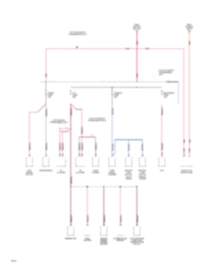
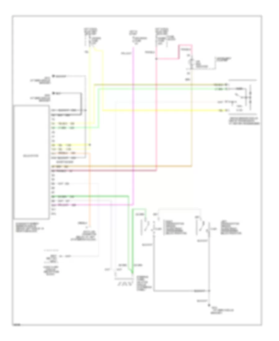
COMPUTER DATA LINES
4.3L
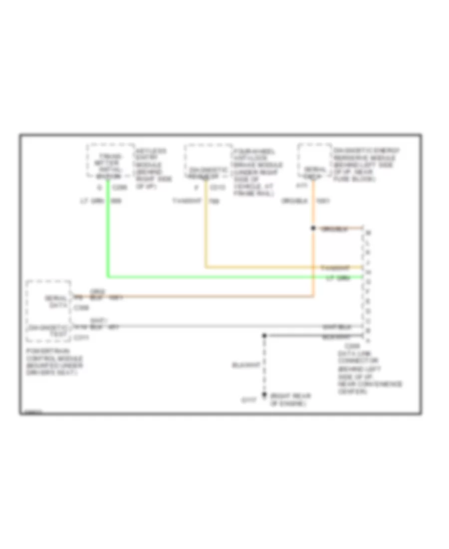
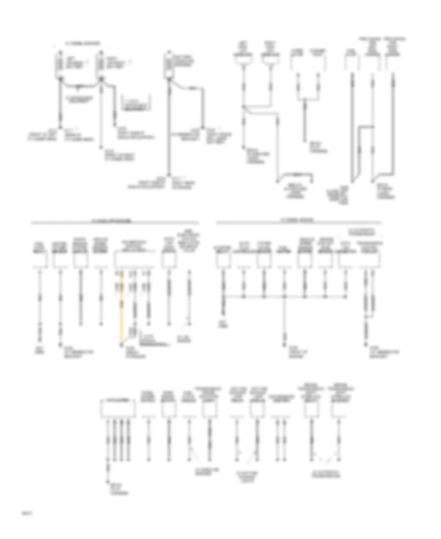
4.3L (VIN Z), Data Link Connector Wiring Diagram for GMC Vandura G1994 2500
List of elements for 4.3L (VIN Z), Data Link Connector Wiring Diagram for GMC Vandura G1994 2500:
- (behind left side of i/p, near convenience center)
- (right rear of engine)
- A11
- A14 diagnostic test c311
- C209
- C296
- C313
- Data
- Data link connector
- Diagnostic energy rerserve module (behind left side of i/p, near fuse block)
- F9 serial data c308
- Four-wheel anti-lock brake module diagnostic (under right side of vehicle, at frame rail)
- G117
- Initial- ization
- Keyless entry module (behind right side of i/p)
- Mitter
- Powertrain control module (mounted under driver's seat)
- Request
- Serial
- Trans-
5.0L
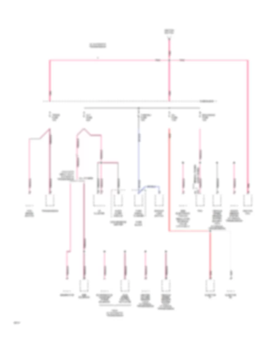
5.0L (VIN H), Data Link Connector Wiring Diagram for GMC Vandura G1994 2500
List of elements for 5.0L (VIN H), Data Link Connector Wiring Diagram for GMC Vandura G1994 2500:
- (behind left side of i/p, near convenience center)
- (right rear of engine)
- A11
- A14 diagnostic test c311
- C209
- C296
- C313
- Data
- Data link connector
- Diagnostic energy rerserve module (behind left side of i/p, near fuse block)
- F9 serial data c308
- Four-wheel anti-lock brake module diagnostic (under right side of vehicle, at frame rail)
- G117
- Initial- ization
- Keyless entry module (behind right side of i/p)
- Mitter
- Powertrain control module (mounted under driver's seat)
- Request
- Serial
- Trans-
5.7L
5.7L (VIN K), Data Link Connector Wiring Diagram for GMC Vandura G1994 2500
List of elements for 5.7L (VIN K), Data Link Connector Wiring Diagram for GMC Vandura G1994 2500:
- (behind left side of i/p, near convenience center)
- (right rear of engine)
- A11
- A14 diagnostic test c311
- C209
- C296
- C313
- Data
- Data link connector
- Diagnostic energy rerserve module (behind left side of i/p, near fuse block)
- F9 serial data c308
- Four-wheel anti-lock brake module diagnostic (under right side of vehicle, at frame rail)
- G117
- Initial- ization
- Keyless entry module (behind right side of i/p)
- Mitter
- Powertrain control module (mounted under driver's seat)
- Request
- Serial
- Trans-
6.5L
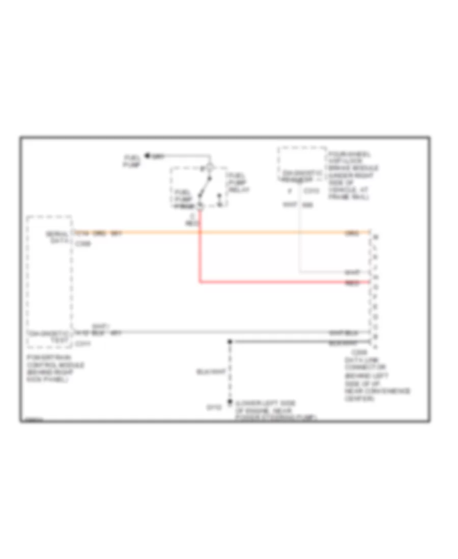
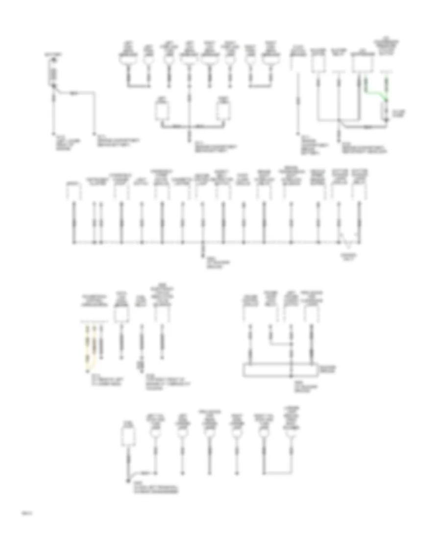
6.5L (VIN P), Data Link Connector Wiring Diagram for GMC Vandura G1994 2500
List of elements for 6.5L (VIN P), Data Link Connector Wiring Diagram for GMC Vandura G1994 2500:
- (behind left side of i/p, near convenience center)
- (lower left side of engine, near power steering pump)
- A12 diagnostic test c311
- C14 serial data c308
- C209
- C313
- Data link connector
- Four-wheel anti-lock brake module diagnostic (under right side of vehicle, at frame rail)
- Fuel pump
- Fuel pump prime
- Fuel pump relay
- G112
- Powertrain control module (behind right kick panel)
- Red
- Request
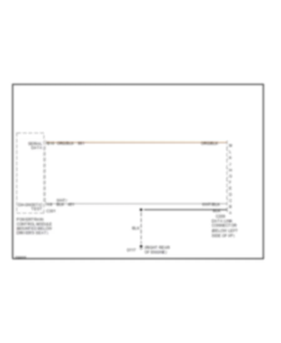
6.5L (VIN Y), Data Link Connector Wiring Diagram for GMC Vandura G1994 2500
List of elements for 6.5L (VIN Y), Data Link Connector Wiring Diagram for GMC Vandura G1994 2500:
- (below left side of i/p)
- (right rear of engine)
- A8 diagnostic test c301
- B10 serial data
- C209
- Data link connector
- G117
- Powertrain control module (mounted below driver's seat)
7.4L
7.4L (VIN N), Data Link Connector Wiring Diagram for GMC Vandura G1994 2500
List of elements for 7.4L (VIN N), Data Link Connector Wiring Diagram for GMC Vandura G1994 2500:
- (behind left side of i/p, near convenience center)
- (right rear of engine)
- A11
- A14 diagnostic test c311
- C209
- C296
- C313
- Data
- Data link connector
- Diagnostic energy rerserve module (behind left side of i/p, near fuse block)
- F9 serial data c308
- Four-wheel anti-lock brake module diagnostic (under right side of vehicle, at frame rail)
- G117
- Initial- ization
- Keyless entry module (behind right side of i/p)
- Mitter
- Powertrain control module (mounted under driver's seat)
- Request
- Serial
- Trans-
CRUISE CONTROL
4.3L
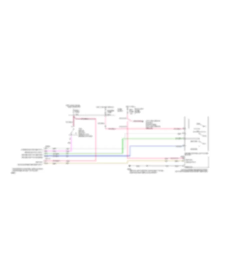
4.3L (VIN Z), Cruise Control Wiring Diagram for GMC Vandura G1994 2500
List of elements for 4.3L (VIN Z), Cruise Control Wiring Diagram for GMC Vandura G1994 2500:
- (behind right kick panel) (v8 vin h,k&n)
- (under driver's seat)
- (v6 vin z)
- Anti-lock brake system (four-wheel anti-lock brake module)
- Auxiliary fuse block
- B10
- Brake bracket)
- Brake in (vent/vac)
- Brk fuse 10a
- C229
- C230
- C235
- C236
- C311
- Closed
- Connected to throttle linkage
- Cruise control input
- Cruise control module (top rear of parking
- Cruise control servo (left rear of engine compartment)
- Cruise control switch
- Cruise on input
- Fuse block
- G201 bus bar ground (behind left side of
- G202 (behind left side of instrument panel,near bus bar ground support)
- Gages fuse 15a
- Ground
- Hot in run
- Hot in run or start
- Ign
- Instrument panel, near fuse block)
- Off
- Pcm/tcm signal
- Pnk/
- Powertrain control module (pcm)
- R/a
- R/a signal
- S/c signal
- Sensor posit input
- Servo posit input
- Servo position sensor
- Speed sensor input
- Speed signal to cruise control
- Support)
- Tan
- To brake cruise release valve (vents with brake pedal depressed)
- Vac valve control
- Vacuum motor
- Vacuum release port
- Vacuum source
- Vacuum valve
- Variable a/c signal
- Vehicle speed sensor buffer (on parking brake support bracket)
- Vent
- Vent valve
- Vent valve control
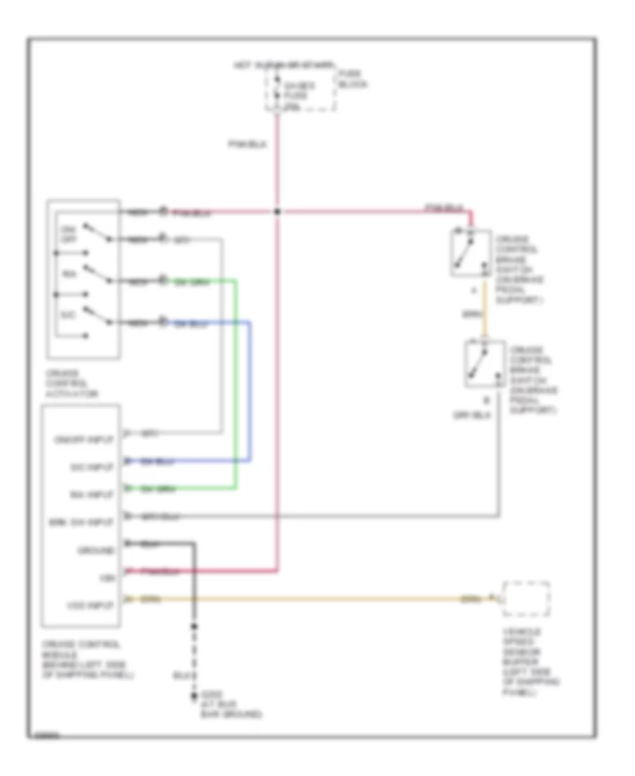
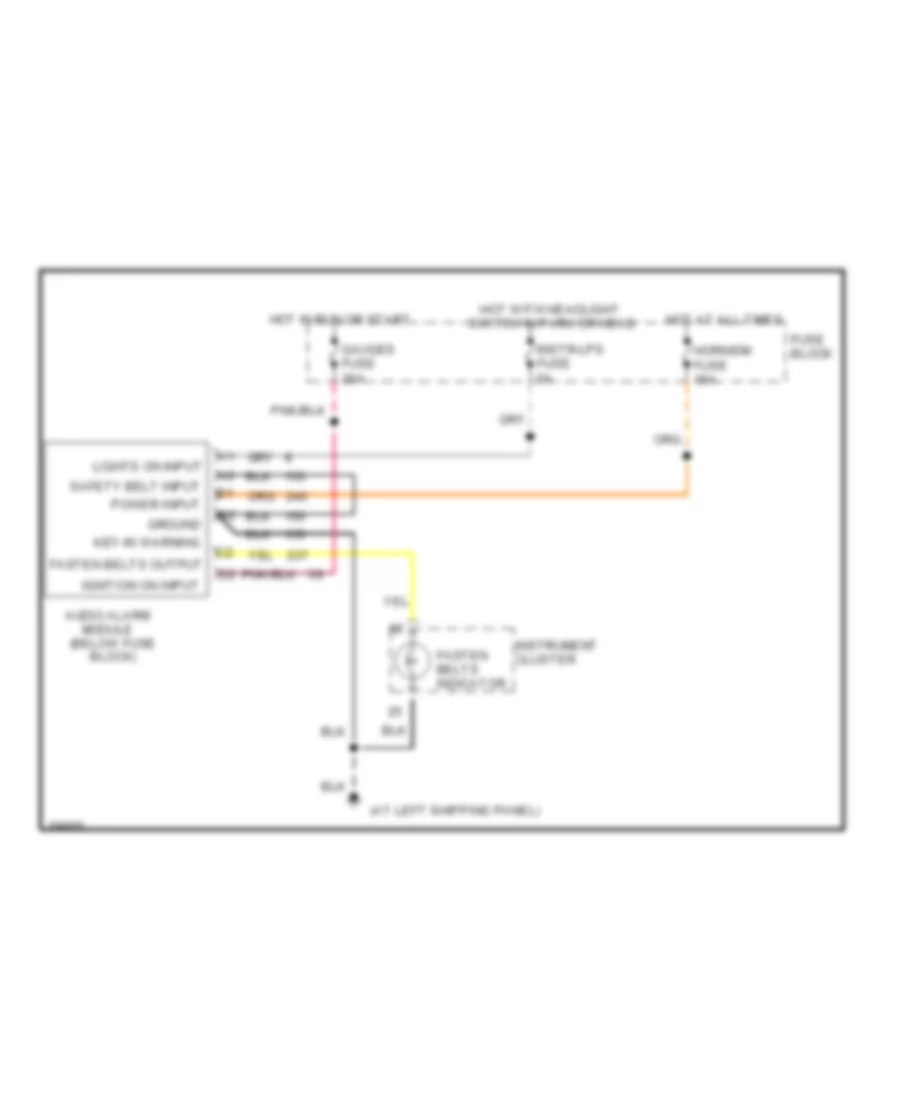
Cruise Control Wiring Diagram, Cutaway Chassis for GMC Vandura G1994 2500
List of elements for Cruise Control Wiring Diagram, Cutaway Chassis for GMC Vandura G1994 2500:
- Brk sw input
- C r/a input
- Cruise control activator
- Cruise control brake switch (on brake pedal support)
- Cruise control module (behind left side of shipping panel)
- Fuse block
- G202 (at bus bar ground)
- Gages fuse 20a
- Ground
- Hot in run or start
- Ign
- Nca
- On/ off
- On/off input
- R/a
- S/c
- S/c input
- Vehicle speed sensor buffer (left side of shipping panel)
- Vss input
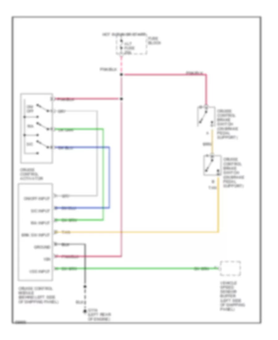
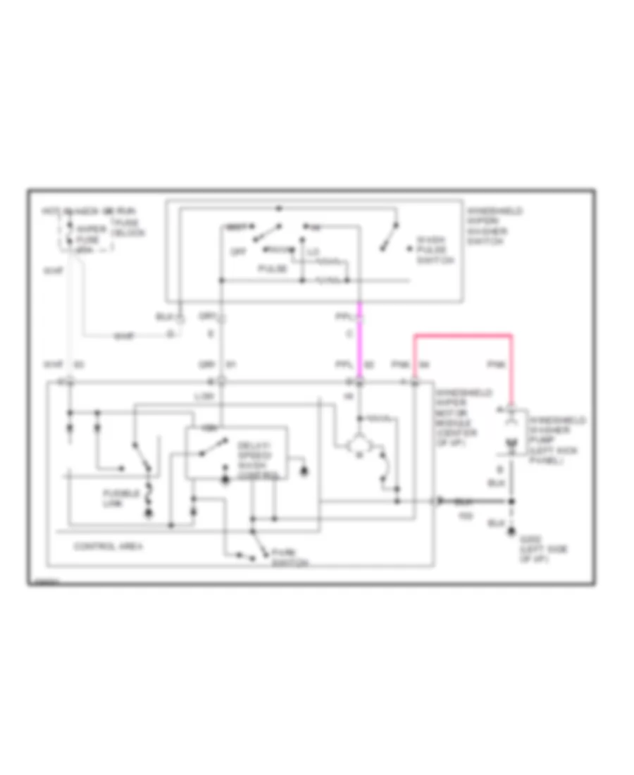
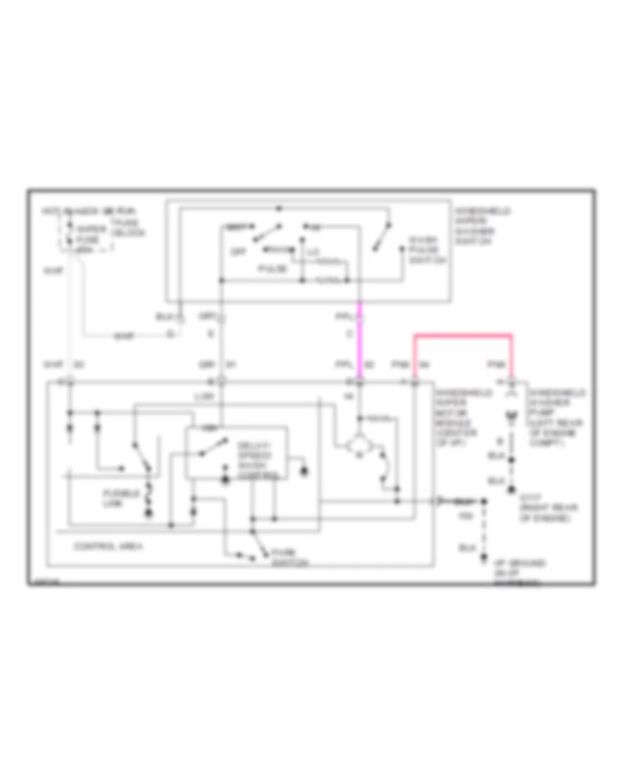
Cruise Control Wiring Diagram, Motor Home Chassis for GMC Vandura G1994 2500
List of elements for Cruise Control Wiring Diagram, Motor Home Chassis for GMC Vandura G1994 2500:
- Alt fuse 20a
- Brk sw input
- Cruise control activator
- Cruise control brake switch (on brake pedal support)
- Cruise control module (behind left side of shipping panel)
- Fuse block
- G114 (left rear of engine)
- Ground
- Hot in run or start
- Ign
- On/ off
- On/off input
- R/a
- R/a input
- S/c
- S/c input
- Tan
- Vehicle speed sensor buffer (left side of shipping panel)
- Vss input
5.0L
5.0L (VIN H), Cruise Control Wiring Diagram for GMC Vandura G1994 2500
List of elements for 5.0L (VIN H), Cruise Control Wiring Diagram for GMC Vandura G1994 2500:
- (behind right kick panel) (v8 vin h,k&n)
- (under driver's seat)
- (v6 vin z)
- Anti-lock brake system (four-wheel anti-lock brake module)
- Auxiliary fuse block
- B10
- Brake bracket)
- Brake in (vent/vac)
- Brk fuse 10a
- C229
- C230
- C235
- C236
- C311
- Closed
- Connected to throttle linkage
- Cruise control input
- Cruise control module (top rear of parking
- Cruise control servo (left rear of engine compartment)
- Cruise control switch
- Cruise on input
- Fuse block
- G201 bus bar ground (behind left side of
- G202 (behind left side of instrument panel,near bus bar ground support)
- Gages fuse 15a
- Ground
- Hot in run
- Hot in run or start
- Ign
- Instrument panel, near fuse block)
- Off
- Pcm/tcm signal
- Pnk/
- Powertrain control module (pcm)
- R/a
- R/a signal
- S/c signal
- Sensor posit input
- Servo posit input
- Servo position sensor
- Speed sensor input
- Speed signal to cruise control
- Support)
- Tan
- To brake cruise release valve (vents with brake pedal depressed)
- Vac valve control
- Vacuum motor
- Vacuum release port
- Vacuum source
- Vacuum valve
- Variable a/c signal
- Vehicle speed sensor buffer (on parking brake support bracket)
- Vent
- Vent valve
- Vent valve control
Cruise Control Wiring Diagram, Cutaway Chassis for GMC Vandura G1994 2500
List of elements for Cruise Control Wiring Diagram, Cutaway Chassis for GMC Vandura G1994 2500:
- Brk sw input
- C r/a input
- Cruise control activator
- Cruise control brake switch (on brake pedal support)
- Cruise control module (behind left side of shipping panel)
- Fuse block
- G202 (at bus bar ground)
- Gages fuse 20a
- Ground
- Hot in run or start
- Ign
- Nca
- On/ off
- On/off input
- R/a
- S/c
- S/c input
- Vehicle speed sensor buffer (left side of shipping panel)
- Vss input
Cruise Control Wiring Diagram, Motor Home Chassis for GMC Vandura G1994 2500
List of elements for Cruise Control Wiring Diagram, Motor Home Chassis for GMC Vandura G1994 2500:
- Alt fuse 20a
- Brk sw input
- Cruise control activator
- Cruise control brake switch (on brake pedal support)
- Cruise control module (behind left side of shipping panel)
- Fuse block
- G114 (left rear of engine)
- Ground
- Hot in run or start
- Ign
- On/ off
- On/off input
- R/a
- R/a input
- S/c
- S/c input
- Tan
- Vehicle speed sensor buffer (left side of shipping panel)
- Vss input
5.7L
5.7L (VIN K), Cruise Control Wiring Diagram for GMC Vandura G1994 2500
List of elements for 5.7L (VIN K), Cruise Control Wiring Diagram for GMC Vandura G1994 2500:
- (behind right kick panel) (v8 vin h,k&n)
- (under driver's seat)
- (v6 vin z)
- Anti-lock brake system (four-wheel anti-lock brake module)
- Auxiliary fuse block
- B10
- Brake bracket)
- Brake in (vent/vac)
- Brk fuse 10a
- C229
- C230
- C235
- C236
- C311
- Closed
- Connected to throttle linkage
- Cruise control input
- Cruise control module (top rear of parking
- Cruise control servo (left rear of engine compartment)
- Cruise control switch
- Cruise on input
- Fuse block
- G201 bus bar ground (behind left side of
- G202 (behind left side of instrument panel,near bus bar ground support)
- Gages fuse 15a
- Ground
- Hot in run
- Hot in run or start
- Ign
- Instrument panel, near fuse block)
- Off
- Pcm/tcm signal
- Pnk/
- Powertrain control module (pcm)
- R/a
- R/a signal
- S/c signal
- Sensor posit input
- Servo posit input
- Servo position sensor
- Speed sensor input
- Speed signal to cruise control
- Support)
- Tan
- To brake cruise release valve (vents with brake pedal depressed)
- Vac valve control
- Vacuum motor
- Vacuum release port
- Vacuum source
- Vacuum valve
- Variable a/c signal
- Vehicle speed sensor buffer (on parking brake support bracket)
- Vent
- Vent valve
- Vent valve control
Cruise Control Wiring Diagram, Cutaway Chassis for GMC Vandura G1994 2500
List of elements for Cruise Control Wiring Diagram, Cutaway Chassis for GMC Vandura G1994 2500:
- Brk sw input
- C r/a input
- Cruise control activator
- Cruise control brake switch (on brake pedal support)
- Cruise control module (behind left side of shipping panel)
- Fuse block
- G202 (at bus bar ground)
- Gages fuse 20a
- Ground
- Hot in run or start
- Ign
- Nca
- On/ off
- On/off input
- R/a
- S/c
- S/c input
- Vehicle speed sensor buffer (left side of shipping panel)
- Vss input
Cruise Control Wiring Diagram, Motor Home Chassis for GMC Vandura G1994 2500
List of elements for Cruise Control Wiring Diagram, Motor Home Chassis for GMC Vandura G1994 2500:
- Alt fuse 20a
- Brk sw input
- Cruise control activator
- Cruise control brake switch (on brake pedal support)
- Cruise control module (behind left side of shipping panel)
- Fuse block
- G114 (left rear of engine)
- Ground
- Hot in run or start
- Ign
- On/ off
- On/off input
- R/a
- R/a input
- S/c
- S/c input
- Tan
- Vehicle speed sensor buffer (left side of shipping panel)
- Vss input
6.5L
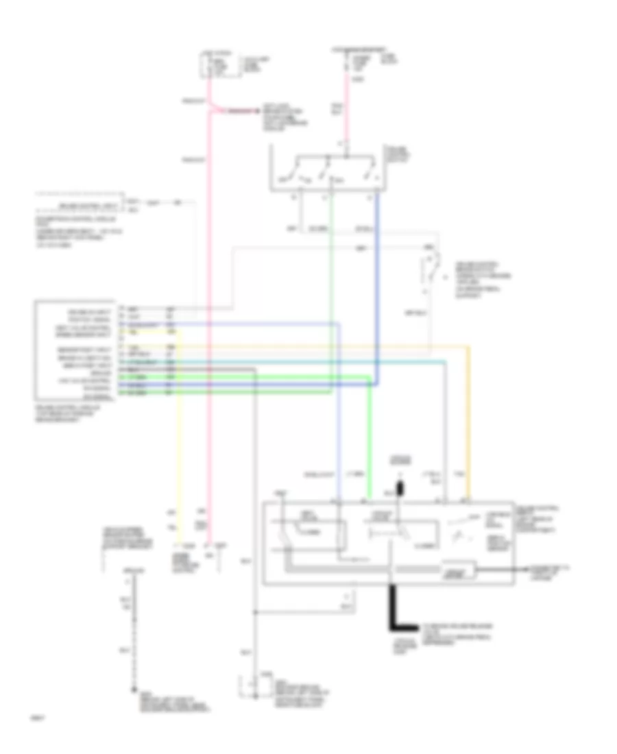
6.5L (VIN P), Cruise Control Wiring Diagram for GMC Vandura G1994 2500
List of elements for 6.5L (VIN P), Cruise Control Wiring Diagram for GMC Vandura G1994 2500:
- (behind left side of instrument panel,
- (on parking brake support bracket)
- 10a
- 20a
- 3 mode elec cruise cntl
- Anti-lock brake system (four-wheel anti-lock brake module)
- Auxiliary fuse block
- Brake switch input
- Brk fuse
- C15
- C308a
- C311a
- Cruise cont sw-engage
- Cruise cont sw-retard
- Cruise control activator switch c230
- D11
- D15
- Ecm 1 fuse
- Engage
- Fuse block
- G202
- Gauges fuse
- Ground
- Hot in run
- Hot in run, bulb
- Hot in start or run
- Ignition
- Near bus bar ground support)
- Off
- Powertrain control module (pcm) (near base of left "b" pillar)
- Retard
- Test or start
- Vehicle speed sensor buffer
- Vehicle speed sensor input
- Vss output
Cruise Control Wiring Diagram, Cutaway Chassis for GMC Vandura G1994 2500
List of elements for Cruise Control Wiring Diagram, Cutaway Chassis for GMC Vandura G1994 2500:
- Brk sw input
- C r/a input
- Cruise control activator
- Cruise control brake switch (on brake pedal support)
- Cruise control module (behind left side of shipping panel)
- Fuse block
- G202 (at bus bar ground)
- Gages fuse 20a
- Ground
- Hot in run or start
- Ign
- Nca
- On/ off
- On/off input
- R/a
- S/c
- S/c input
- Vehicle speed sensor buffer (left side of shipping panel)
- Vss input
Cruise Control Wiring Diagram, Motor Home Chassis for GMC Vandura G1994 2500
List of elements for Cruise Control Wiring Diagram, Motor Home Chassis for GMC Vandura G1994 2500:
- Alt fuse 20a
- Brk sw input
- Cruise control activator
- Cruise control brake switch (on brake pedal support)
- Cruise control module (behind left side of shipping panel)
- Fuse block
- G114 (left rear of engine)
- Ground
- Hot in run or start
- Ign
- On/ off
- On/off input
- R/a
- R/a input
- S/c
- S/c input
- Tan
- Vehicle speed sensor buffer (left side of shipping panel)
- Vss input
7.4L
7.4L (VIN N), Cruise Control Wiring Diagram for GMC Vandura G1994 2500
List of elements for 7.4L (VIN N), Cruise Control Wiring Diagram for GMC Vandura G1994 2500:
- (behind right kick panel) (v8 vin h,k&n)
- (under driver's seat)
- (v6 vin z)
- Anti-lock brake system (four-wheel anti-lock brake module)
- Auxiliary fuse block
- B10
- Brake bracket)
- Brake in (vent/vac)
- Brk fuse 10a
- C229
- C230
- C235
- C236
- C311
- Closed
- Connected to throttle linkage
- Cruise control input
- Cruise control module (top rear of parking
- Cruise control servo (left rear of engine compartment)
- Cruise control switch
- Cruise on input
- Fuse block
- G201 bus bar ground (behind left side of
- G202 (behind left side of instrument panel,near bus bar ground support)
- Gages fuse 15a
- Ground
- Hot in run
- Hot in run or start
- Ign
- Instrument panel, near fuse block)
- Off
- Pcm/tcm signal
- Pnk/
- Powertrain control module (pcm)
- R/a
- R/a signal
- S/c signal
- Sensor posit input
- Servo posit input
- Servo position sensor
- Speed sensor input
- Speed signal to cruise control
- Support)
- Tan
- To brake cruise release valve (vents with brake pedal depressed)
- Vac valve control
- Vacuum motor
- Vacuum release port
- Vacuum source
- Vacuum valve
- Variable a/c signal
- Vehicle speed sensor buffer (on parking brake support bracket)
- Vent
- Vent valve
- Vent valve control
Cruise Control Wiring Diagram, Cutaway Chassis for GMC Vandura G1994 2500
List of elements for Cruise Control Wiring Diagram, Cutaway Chassis for GMC Vandura G1994 2500:
- Brk sw input
- C r/a input
- Cruise control activator
- Cruise control brake switch (on brake pedal support)
- Cruise control module (behind left side of shipping panel)
- Fuse block
- G202 (at bus bar ground)
- Gages fuse 20a
- Ground
- Hot in run or start
- Ign
- Nca
- On/ off
- On/off input
- R/a
- S/c
- S/c input
- Vehicle speed sensor buffer (left side of shipping panel)
- Vss input
Cruise Control Wiring Diagram, Motor Home Chassis for GMC Vandura G1994 2500
List of elements for Cruise Control Wiring Diagram, Motor Home Chassis for GMC Vandura G1994 2500:
- Alt fuse 20a
- Brk sw input
- Cruise control activator
- Cruise control brake switch (on brake pedal support)
- Cruise control module (behind left side of shipping panel)
- Fuse block
- G114 (left rear of engine)
- Ground
- Hot in run or start
- Ign
- On/ off
- On/off input
- R/a
- R/a input
- S/c
- S/c input
- Tan
- Vehicle speed sensor buffer (left side of shipping panel)
- Vss input
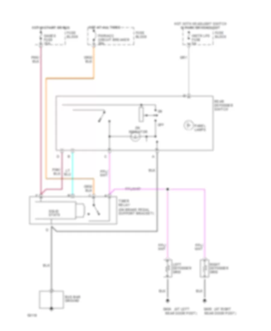
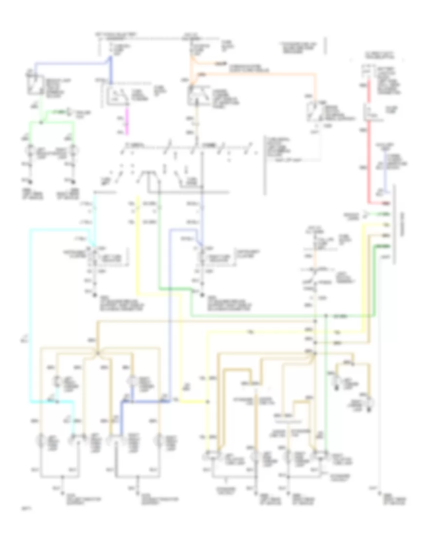
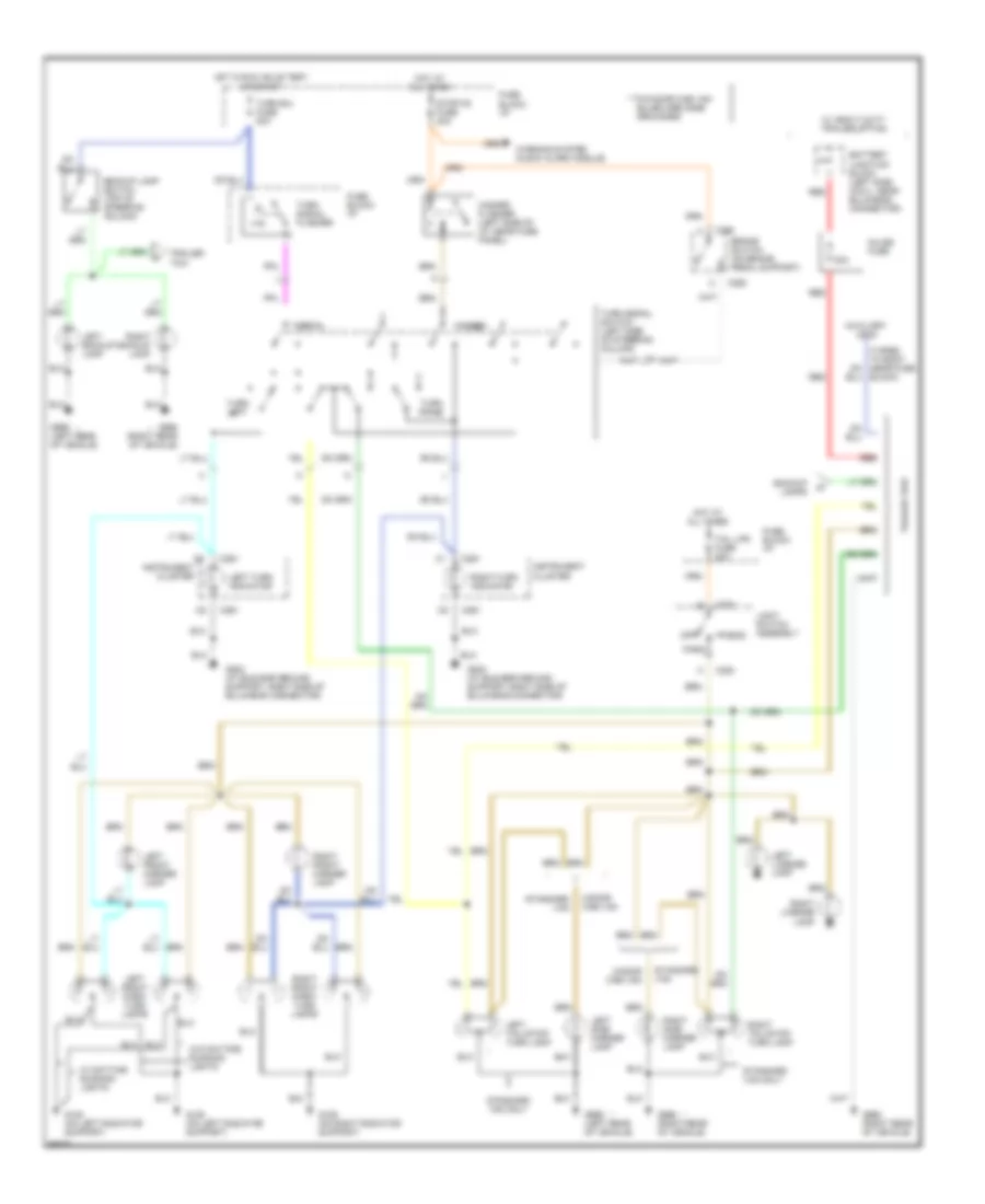
DEFOGGERS
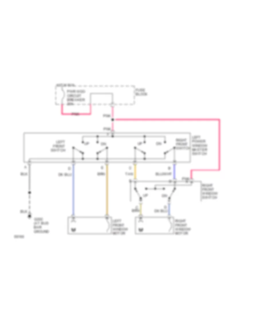
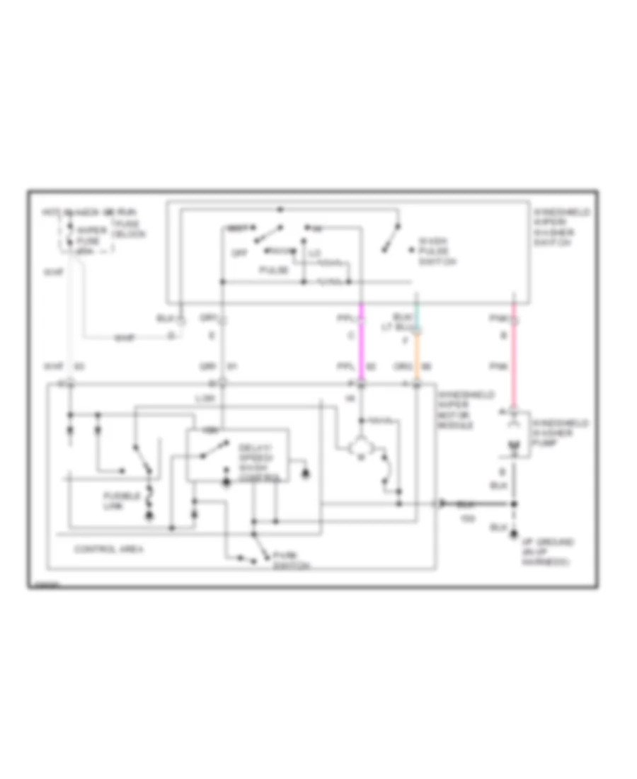
Defogger Wiring Diagram for GMC Vandura G1994 2500
List of elements for Defogger Wiring Diagram for GMC Vandura G1994 2500:
- (at left
- (at right
- (on brake pedal support bracket)
- Bus bar ground
- Fuse block
- G404
- G405
- Gages fuse 15a
- Hot at all times
- Hot in start or run
- Hot with headlight switch in park or headlight
- Indicator
- Instr lps fuse 5a
- Left defogger grid
- Off
- Panel lamps
- Pwr/acc circuit breaker 30a
- Rear defogger switch
- Rear door post)
- Right defogger grid
- Solid state
- Timer relay
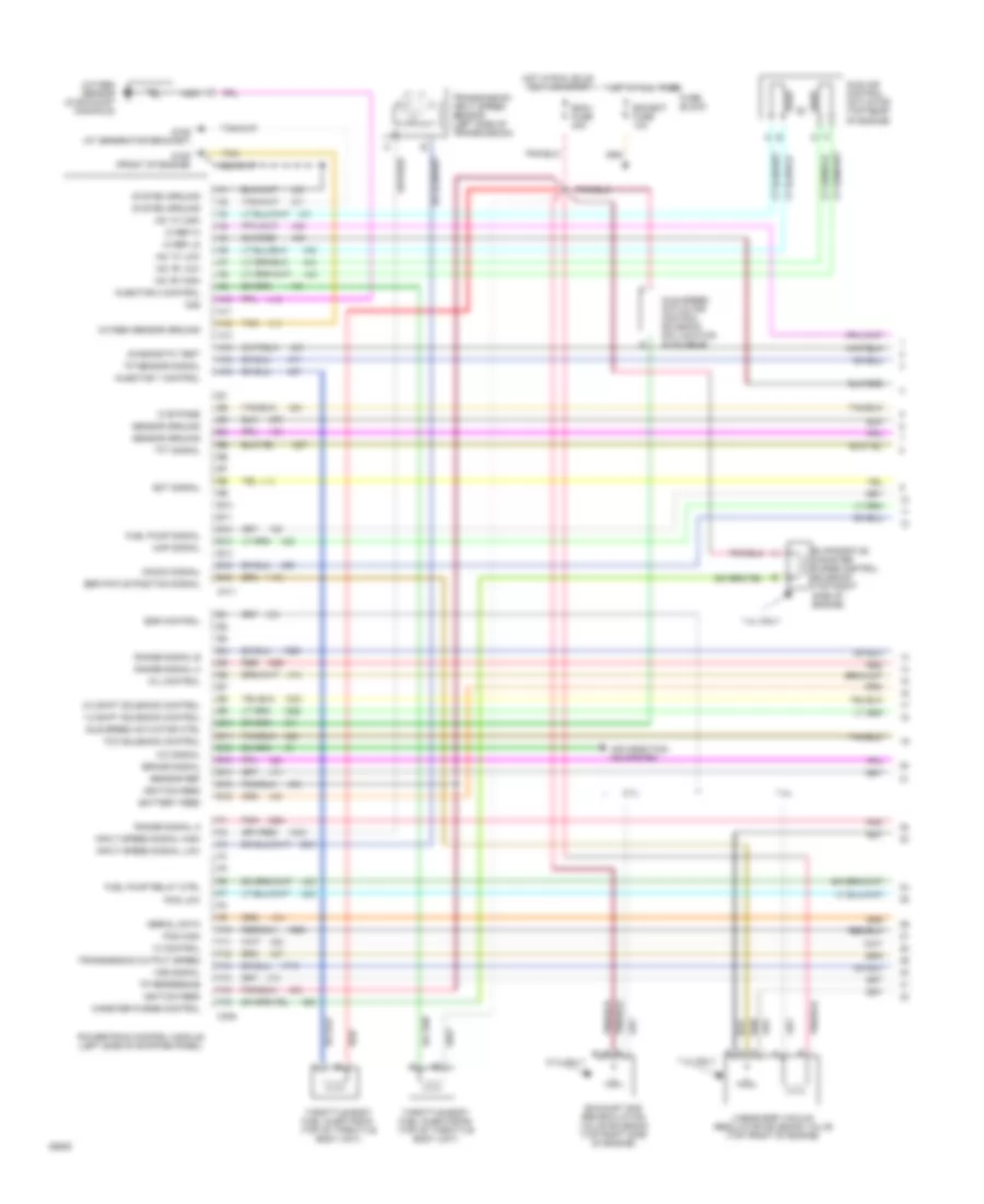
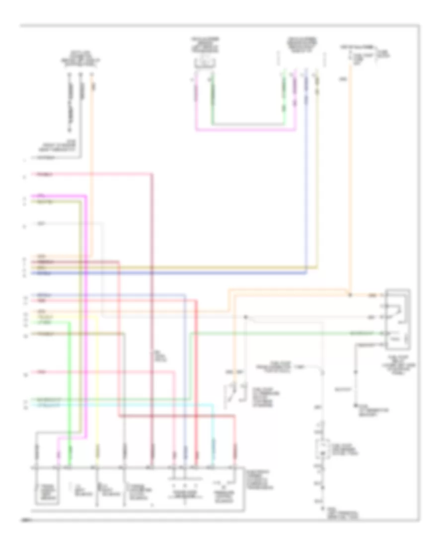
ENGINE PERFORMANCE
4.3L
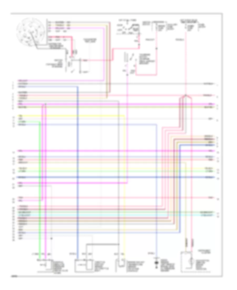
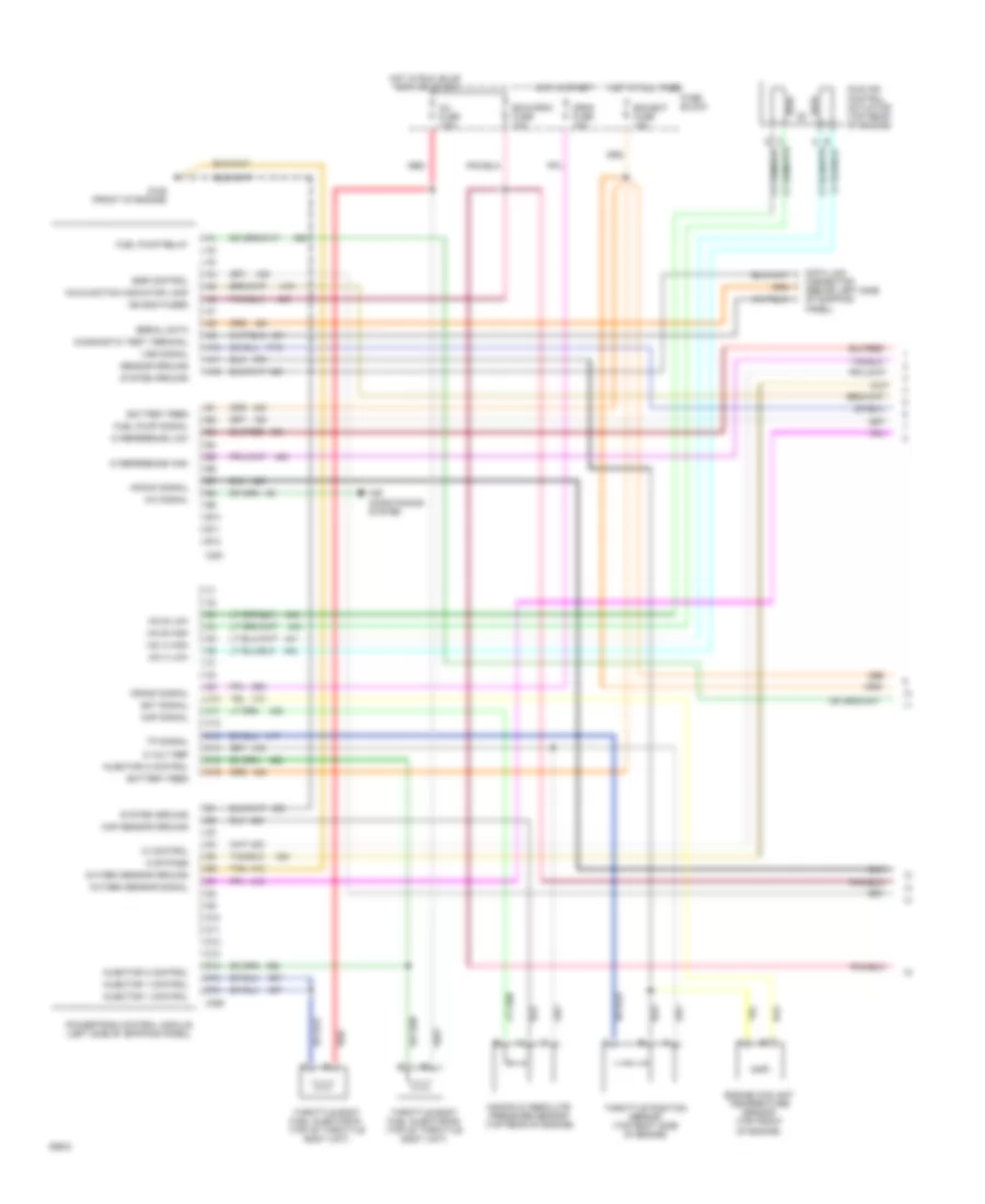
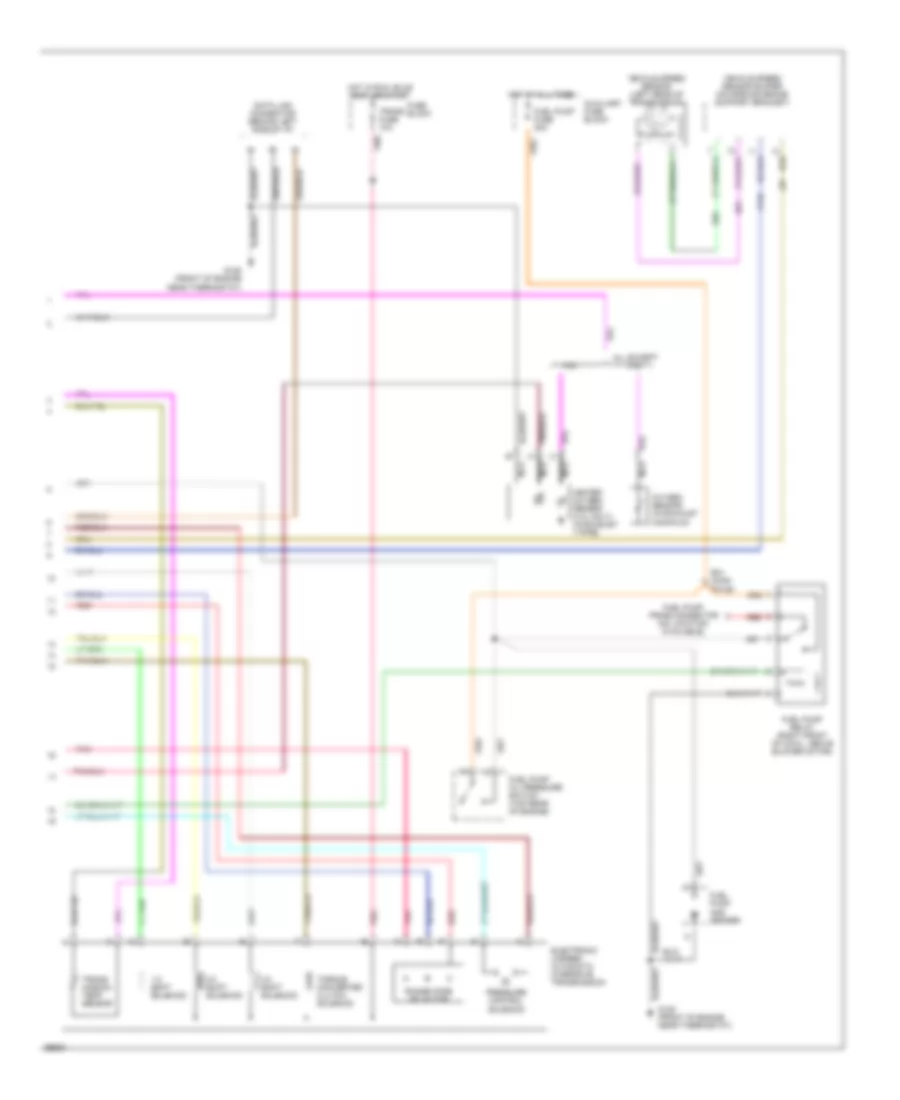
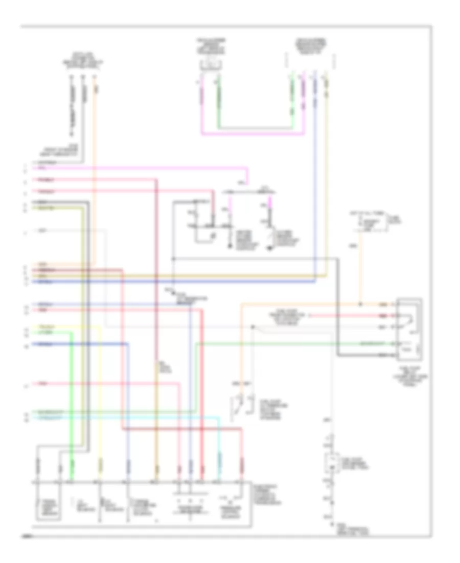
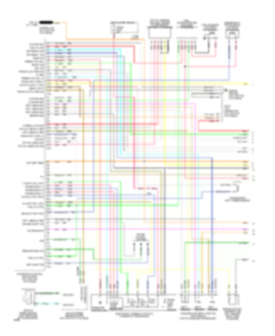
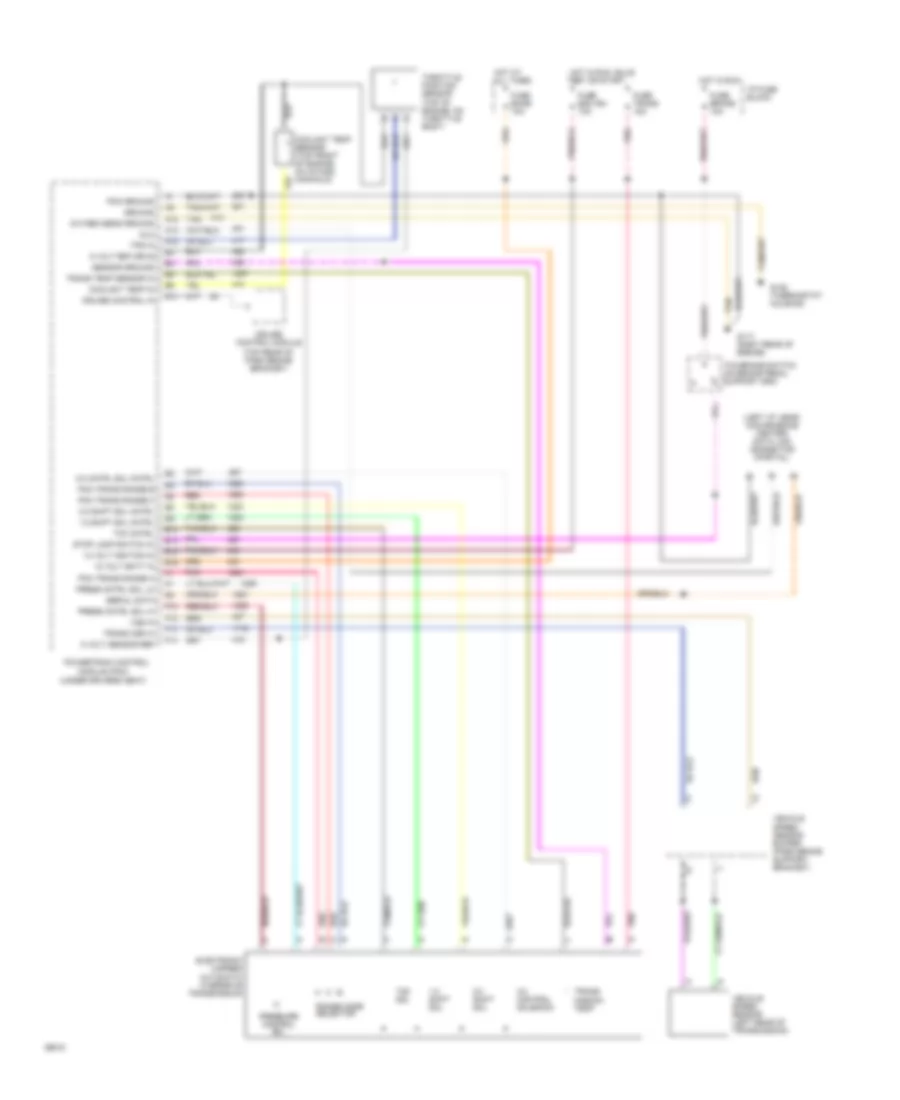
4.3L (VIN Z), Engine Performance Wiring Diagrams, 4L60E A/T (1 of 3) for GMC Vandura G1994 2500
List of elements for 4.3L (VIN Z), Engine Performance Wiring Diagrams, 4L60E A/T (1 of 3) for GMC Vandura G1994 2500:
- (front of engine, near thermostat)
- 12v battery
- 12v ignition
- 5v return a
- 5v return b
- 5v sensor ref
- A/c on signal in
- A10
- A11
- A12
- A13
- A14
- A15
- A16
- Air condition- ing system
- B10
- B11
- B12
- B13
- B14
- B15
- B16
- Brake sw to pcm
- C308
- C311
- Cruise control system
- Cruise ind reg grd
- Distributor ref hi
- Distributor ref lo
- Dlc
- Dlc serial data
- E10
- E11
- E12
- E13
- E14
- E15
- E16
- Ecm b fuse 10a
- Ecm i fuse 10a
- Egr valve solenoid
- Elec fuel pump in
- Engine coolant temp sens
- Exhaust gas recirculation valve solenoid (top right side of engine)
- F10
- F11
- F12
- F13
- F14
- F15
- F16
- Fuel pump relay drive
- Fuse block
- G117 (rear of engine, near distributor)
- G125
- Hot at all times
- Hot in run, bulb test, or start
- Idle air control unit (right side of throttle body)
- Ignition bypass
- Ignition control (ic)
- Knock sensor in
- Lo side inj a
- Lo side inj b
- Map sensor in
- Mil indicator ctrl
- Oxygen sensor hi
- Oxygen sensor lo
- Pcm to trans temp sensor
- Pcm trans force mtr hi
- Pcm trans force mtr lo
- Pcm trans range a
- Pcm trans range b
- Pcm trans range c
- Pcm trans shift sol a
- Pcm trans shift sol b
- Pnk
- Powertrain control module (under driver's seat)
- Red
- Stepper coil a hi
- Stepper coil a lo
- Stepper coil b hi
- Stepper coil b lo
- System ground
- Tan
- Tcc clutch ctrl
- Throttle body fuel injector #1 (top of throttle body unit)
- Throttle body fuel injector #2 (top of throttle body unit)
- Throttle position signal
- Trans fuse 15a
- Trans shift 2/3 solenoid
- Vss buffer signal
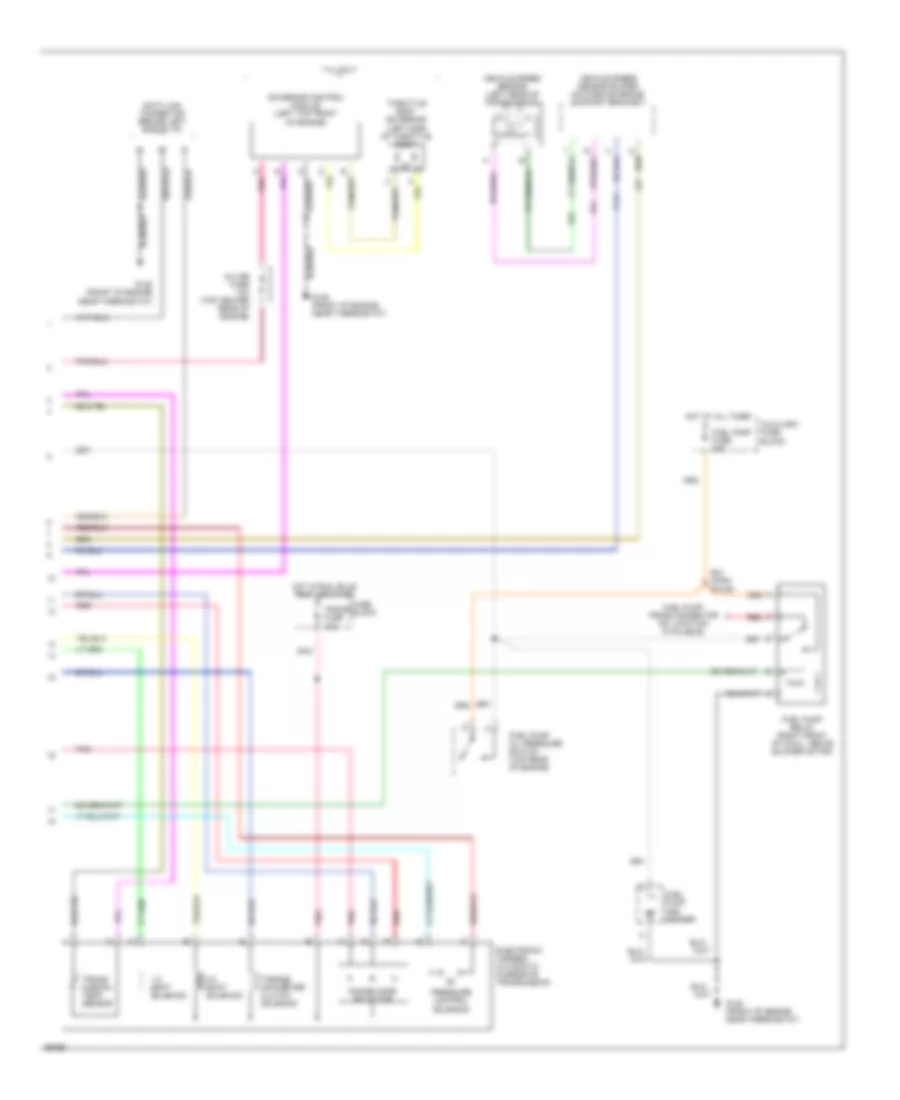
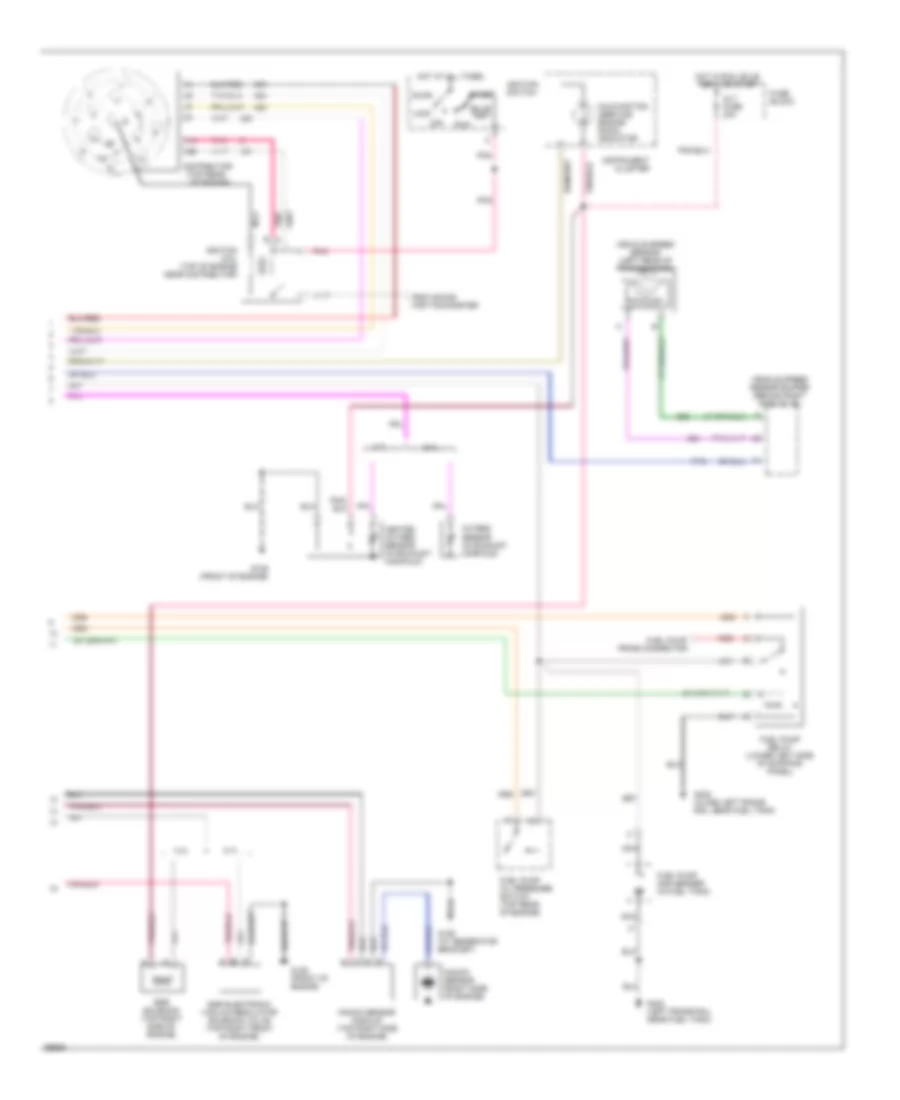
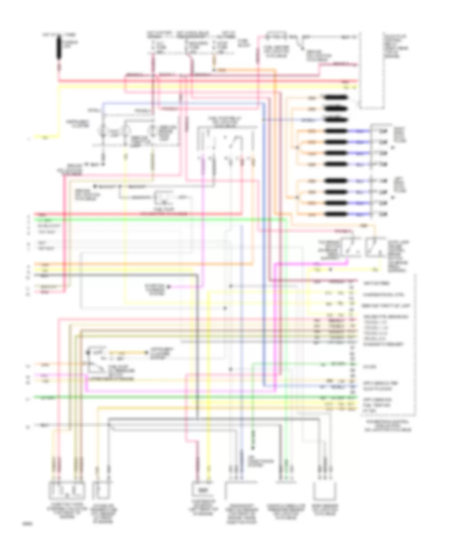
4.3L (VIN Z), Engine Performance Wiring Diagrams, 4L60E A/T (2 of 3) for GMC Vandura G1994 2500
List of elements for 4.3L (VIN Z), Engine Performance Wiring Diagrams, 4L60E A/T (2 of 3) for GMC Vandura G1994 2500:
- (center rear
- Accy
- Auxiliary fuse block
- Brake fuse 20a
- Bulb test
- C11
- C12
- Distributor
- Engine coolant temperature sensor (on intake manifold)
- Fuse block
- Gages fuse 20a
- Hot at all times
- Hot in run
- Hot in run, bulb test, or start
- Ignition coil (top right rear of engine)
- Ignition switch
- Instrument cluster
- Knock sensor (left rear of engine, near oil pressure sender)
- Lock
- Malfunction (service engine soon) indicator
- Manifold absolute pressure sensor (above valve cover)
- Nca
- Of engine)
- Off
- Pnk
- Pnk b
- Pnk/
- Red
- Run
- Start
- Tachometer test lead
- Tcc/brake switch (on brake pedal support bracket)
- Throttle position sensor (on throttle body)
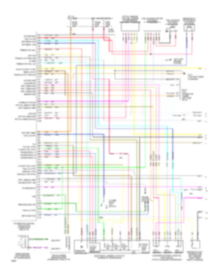
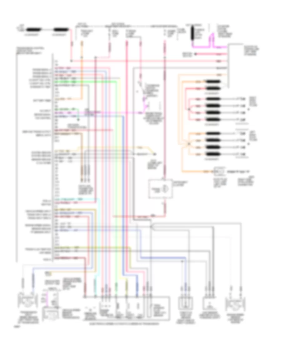
4.3L (VIN Z), Engine Performance Wiring Diagrams, 4L60E A/T (3 of 3) for GMC Vandura G1994 2500
List of elements for 4.3L (VIN Z), Engine Performance Wiring Diagrams, 4L60E A/T (3 of 3) for GMC Vandura G1994 2500:
- 1-2 shift soleniod
- 2-3 shift soleniod
- 3-2 shift solenoid
- 4.3l
- All except 4.3l
- Auxiliary fuse block
- B/h conn pin b3
- Data link connector (behind left side of i/p)
- Electronic 4-speed automatic overdrive transmission
- Fuel pump and sender
- Fuel pump fuse 20a
- Fuel pump oil pressure switch (top rear of engine)
- Fuel pump prime connector (no location available)
- Fuel pump relay (right front of cowl, above blower motor)
- Fuse block
- G125 (front of engine near thermostat)
- Heated oxygen sensor (4.3l only) (in exhaust y-pipe)
- Hot at all times
- Hot in run, bulb test, or start
- Nca
- Oxygen sensor (in exhaust manifold)
- Pnk
- Pressure control solenoid
- Range mode selector
- Red
- Torque converter clutch solenoid
- Trans fuse 10a
- Trans- mission temp sensor
- Vehicle speed sensor (left rear of transmission)
- Vehicle speed sensor buffer (on parking brake support bracket)
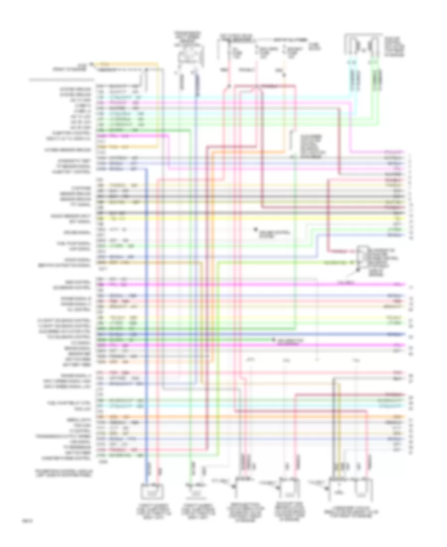
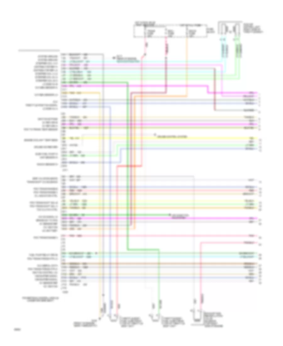
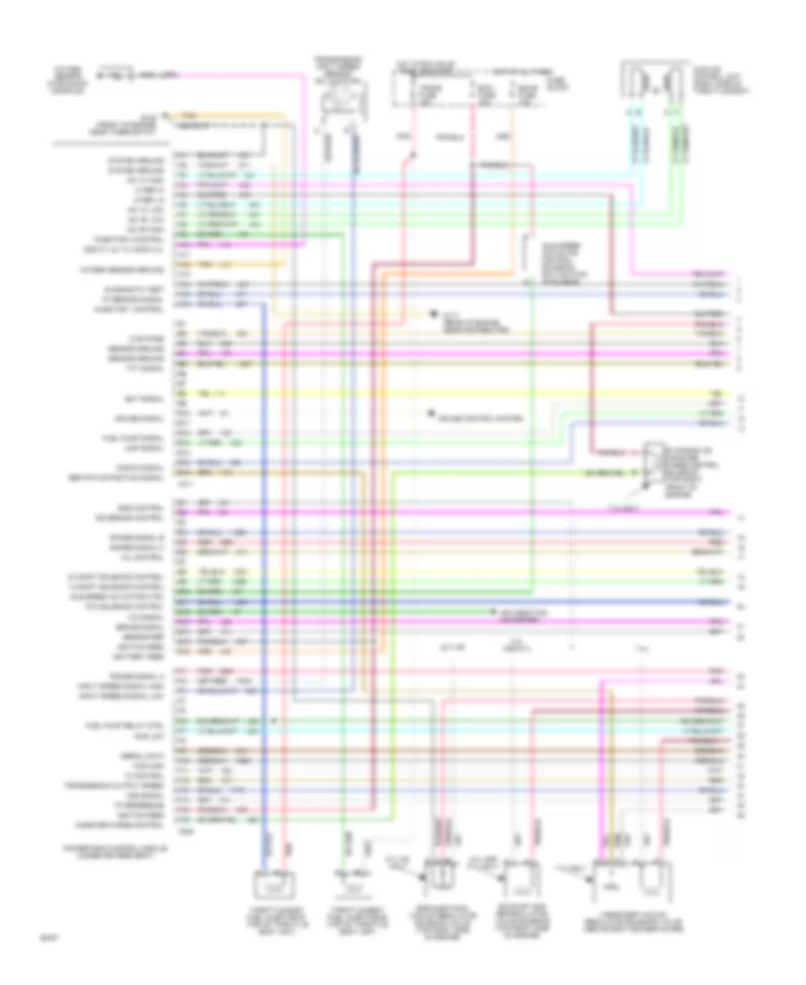
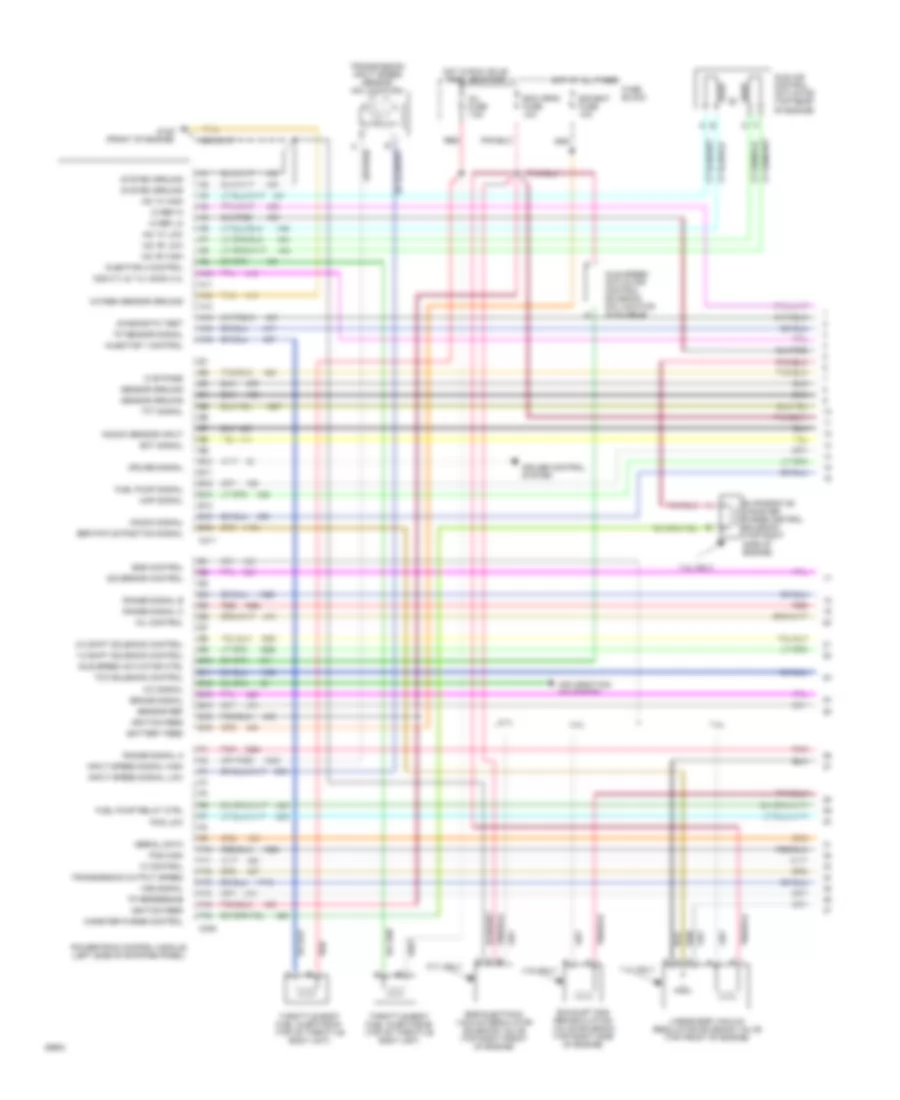
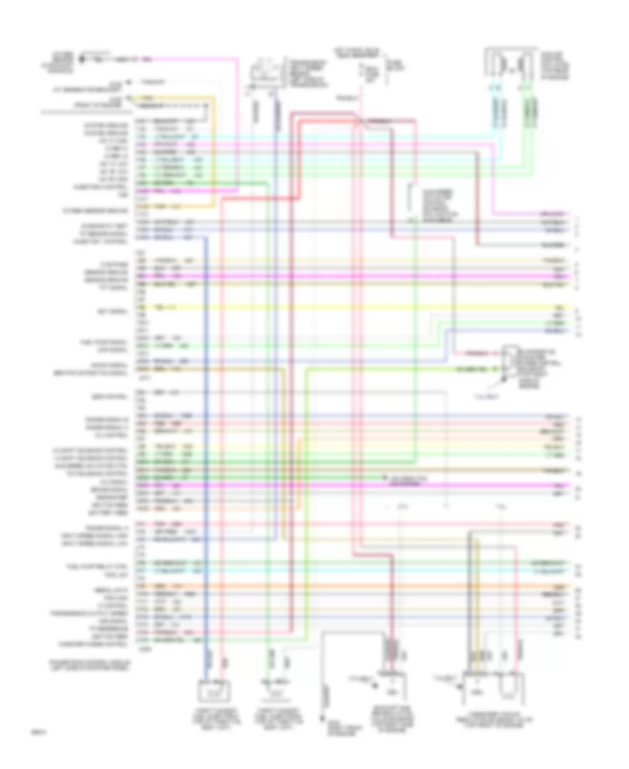
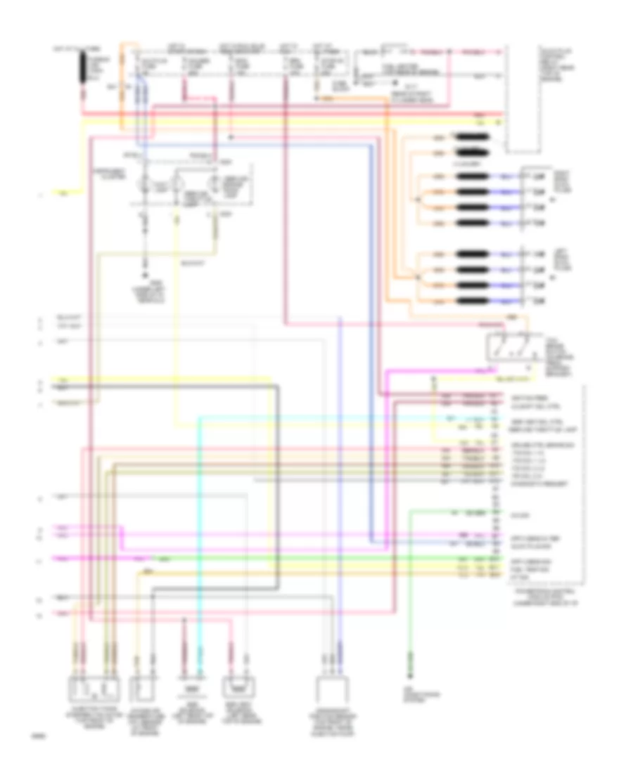
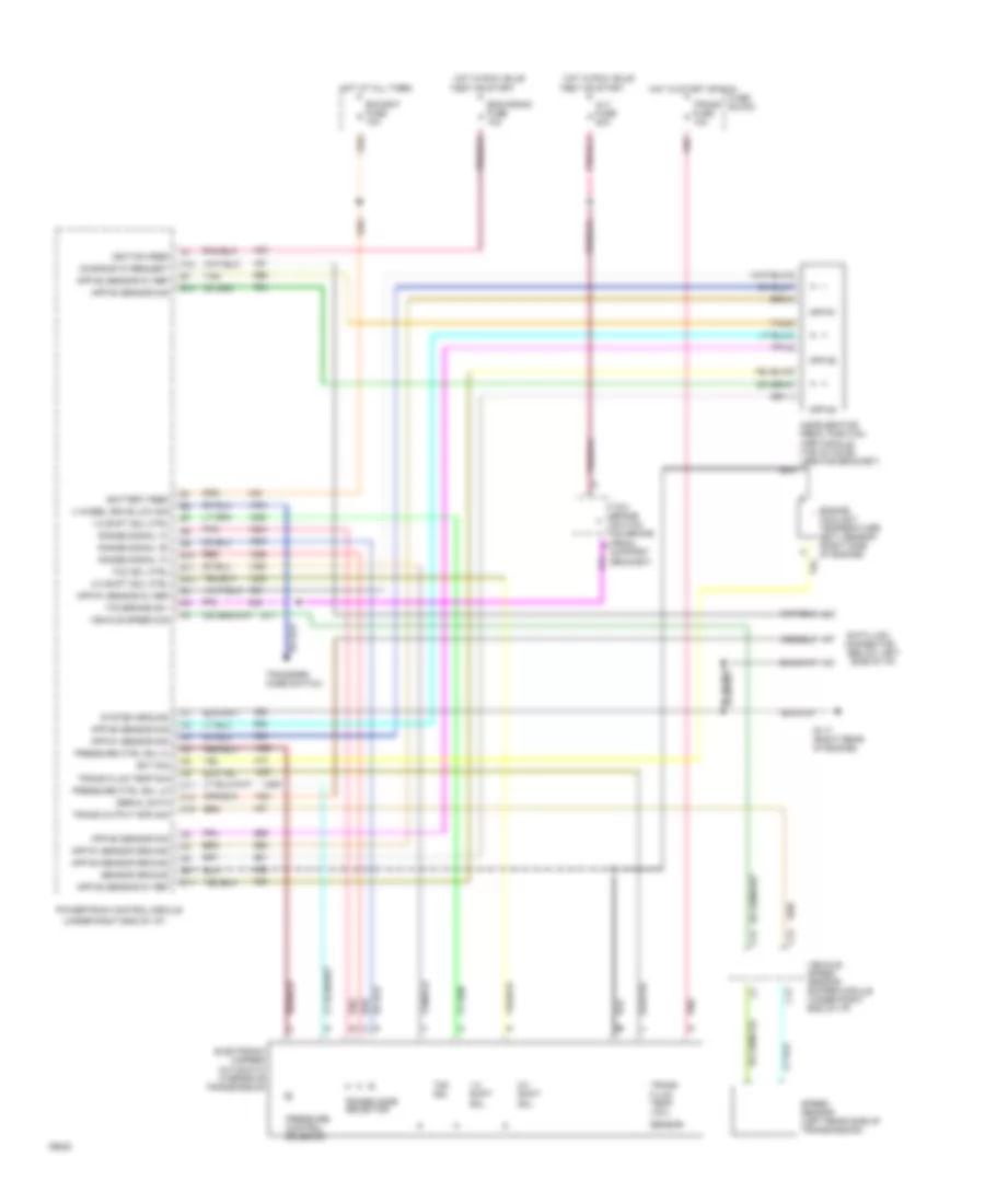
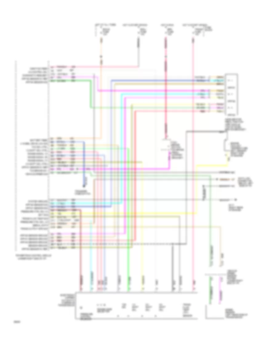
4.3L (VIN Z), Engine Performance Wiring Diagrams, 4L80E A/T (1 of 3) for GMC Vandura G1994 2500
List of elements for 4.3L (VIN Z), Engine Performance Wiring Diagrams, 4L80E A/T (1 of 3) for GMC Vandura G1994 2500:
- 1-2 shift solenoid control
- 2-3 shift solenoid control
- 4.3l and 5.7l
- 4.3l and 5.7l only
- 5.7l hd
- 5.7l hd only
- 7.4l
- 7.4l only
- A/c signal
- A10
- A11
- A12
- A13
- A14
- A15
- A16
- Air condition- ing system
- B10
- B11
- B12
- B13
- B14
- B15
- B16
- Battery feed
- Brake signal
- C308
- C311
- Canister purge control
- Cruise control system
- Cruise signal
- Diagnostic test
- E10
- E11
- E12
- E13
- E14
- E15
- E16
- Ecm b fuse 10a
- Ecm i fuse 10a
- Ect signal
- Egr control
- Egr electonic vacuum regulator soleniod valve (top right side of engine)
- Egr pintle position signal
- Evaporative canister purge control solenoid (top right front of engine)
- Exhaust gas recirculation valve solenoid (top right side of engine)
- F10
- F11
- F12
- F13
- F14
- F15
- F16
- Fuel pump relay ctrl
- Fuel pump signal
- Fuse block
- G117 (rear of engine, near distributor)
- G125 (front of engine near thermostat)
- Governor control
- Hot at all times
- Hot in run, bulb test, or start
- Iac "a" high
- Iac "a" low
- Iac "b" high
- Iac "b" low
- Ic bypass
- Ic control
- Ic ref hi
- Ic ref lo
- Idle air control unit (right side of throttle body)
- Idle speed actuator control solenoid (no location available)
- Idle speed actuator ctrl
- Ignition feed
- Injector 1 control
- Injector 2 control
- Input speed signal high
- Input speed signal low
- Knock signal
- Linear egr vacuum regulator solenoid valve (above right rocker cover)
- Map signal
- Mil control
- Nca
- O2s 5.7l & 7.4l h2os 4.3l
- Oxygen sensor (in exhaust manifold)
- Oxygen sensor ground
- Pcs high
- Pcs low
- Pnk
- Powertrain control module (under driver's seat)
- Range signal a
- Range signal b
- Range signal c
- Red
- Sensor ground
- Sensor ref
- Serial data
- System ground
- Tan
- Tcc solenoid control
- Tft signal
- Throttle body fuel injector #1 (top of throttle body unit)
- Throttle body fuel injector #2 (top of throttle body unit)
- Tp reference
- Tp sensor signal
- Trans fuse 15a
- Transmission input speed sensor (no location)
- Transmission output speed
- Vss signal
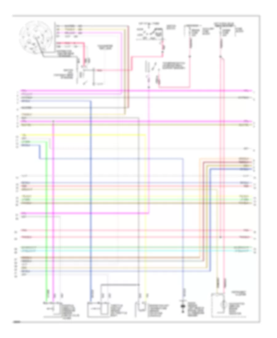
4.3L (VIN Z), Engine Performance Wiring Diagrams, 4L80E A/T (2 of 3) for GMC Vandura G1994 2500
List of elements for 4.3L (VIN Z), Engine Performance Wiring Diagrams, 4L80E A/T (2 of 3) for GMC Vandura G1994 2500:
- (center rear
- Accy
- Auxiliary fuse block
- Brake fuse 20a
- Bulb test
- C11
- C12
- Distributor
- Engine coolant temperature sensor (on intake manifold)
- Fuse block
- Gages fuse 20a
- Hot at all times
- Hot in run
- Hot in run, bulb test, or start
- Ignition coil (top right rear of engine)
- Ignition switch
- Instrument cluster
- Knock sensor (left rear of engine, near oil pressure sender)
- Lock
- Malfunction (service engine soon) indicator
- Manifold absolute pressure sensor (above valve cover)
- Nca
- Of engine)
- Off
- Pnk
- Pnk b
- Pnk/
- Red
- Run
- Start
- Tachometer test lead
- Tcc/brake switch (on brake pedal support bracket)
- Throttle position sensor (on throttle body)
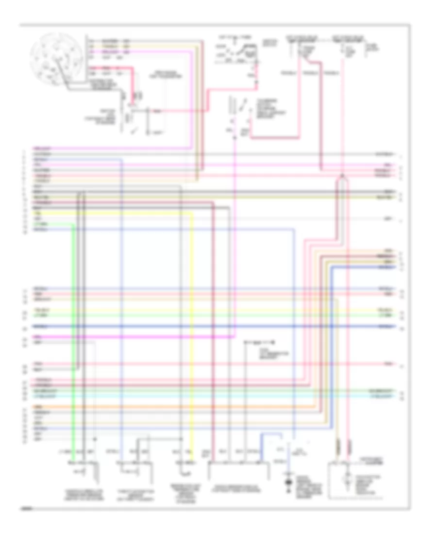
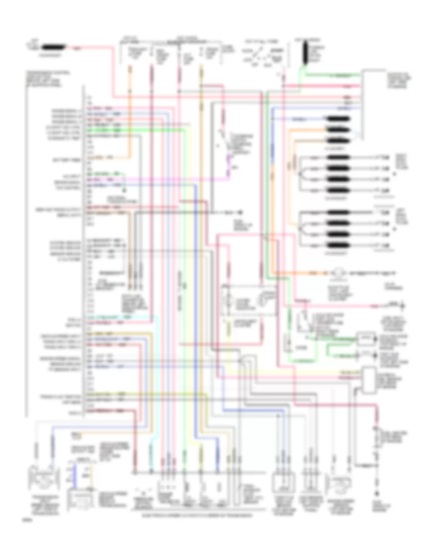
4.3L (VIN Z), Engine Performance Wiring Diagrams, 4L80E A/T (3 of 3) for GMC Vandura G1994 2500
List of elements for 4.3L (VIN Z), Engine Performance Wiring Diagrams, 4L80E A/T (3 of 3) for GMC Vandura G1994 2500:
- 1-2 shift soleniod
- 2-3 shift soleniod
- 7.4l only
- Auxiliary fuse block
- B/h conn pin b3
- Data link connector (behind left side of i/p)
- Electronic 4-speed automatic overdrive transmission
- Fuel pump and sender
- Fuel pump fuse 20a
- Fuel pump oil pressure switch (top rear of engine)
- Fuel pump prime connector (no location available)
- Fuel pump relay (right front of cowl, above blower motor)
- Fuse block
- G125 (front of engine near thermostat)
- G125 (front of engine, near thermostat)
- Governor control module (left top front of engine)
- Hot at all times
- Hot in run, bulb test, or start
- In-line fuse 10a (top center rear of engine)
- Pnk
- Pressure control solenoid
- Range mode selector
- Red
- Throttle body governor (left side of throttle body)
- Torque converter clutch solenoid
- Trans fuse 10a
- Trans- mission temp sensor
- Vehicle speed sensor (left rear of transmission)
- Vehicle speed sensor buffer (on parking brake support bracket)
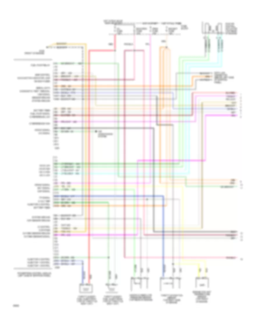
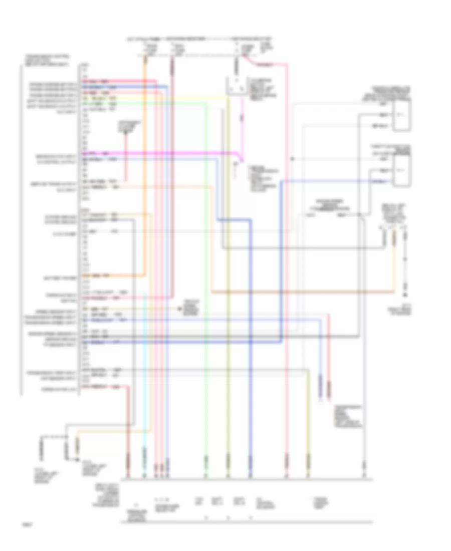
4.3L (VIN Z), Engine Performance Wiring Diagrams, A/T (1 of 3) for GMC Vandura G1994 2500
List of elements for 4.3L (VIN Z), Engine Performance Wiring Diagrams, A/T (1 of 3) for GMC Vandura G1994 2500:
- 1-2 shift solenoid control
- 2-3 shift solenoid control
- 4.3l
- 4.3l only
- 5.7l
- 5.7l only
- 7.4l
- 7.4l only
- A/c signal
- A10
- A11
- A12
- A13
- A14
- A15
- A16
- Air condition- ing system
- B10
- B11
- B12
- B13
- B14
- B15
- B16
- Battery feed
- Brake signal
- C308
- C311
- Canister purge control
- Cruise control system
- Cruise signal
- Diagnostic test
- E10
- E11
- E12
- E13
- E14
- E15
- E16
- Ecm bat fuse 10a
- Ecm crnk fuse 10a
- Ect signal
- Egr control
- Egr electonic vacuum regulator soleniod valve (top right front of engine)
- Egr pintle position signal
- Evaporative canister purge control solenoid (top right side of engine)
- Exhaust gas recirculation valve solenoid (top right side of engine)
- F10
- F11
- F12
- F13
- F14
- F15
- F16
- Fuel pump relay ctrl
- Fuel pump signal
- Fuse block
- G125 (front of engine)
- Governor control
- Hot at all times
- Hot in run, bulb test, or start
- Iac "a" high
- Iac "a" low
- Iac "b" high
- Iac "b" low
- Ic bypass
- Ic control
- Ic ref hi
- Ic ref lo
- Idle air control actuator (top rear of engine)
- Idle speed actuator control solenoid (no location available)
- Idle speed actuator ctrl
- Ignition feed
- Inj fuse 7.5a
- Injector 1 control
- Injector 2 control
- Input speed signal high
- Input speed signal low
- Knock sensor input
- Knock signal
- Linear egr vacuum regulator solenoid valve (top front of engine)
- Map signal
- Mil control
- O2s 5.7l & 7.4l h2os 4.3l
- Oxygen sensor ground
- Pcs high
- Pcs low
- Pnk
- Powertrain control module (left side of shipping panel)
- Range signal a
- Range signal b
- Range signal c
- Red
- Sensor ground
- Sensor ref
- Serial data
- System ground
- Tan
- Tcc solenoid control
- Tft signal
- Throttle body fuel injector #1 (top of throttle body unit)
- Throttle body fuel injector #2 (top of throttle body unit)
- Tp reference
- Tp sensor signal
- Transmission input speed sensor (no location)
- Transmission output speed
- Vss signal
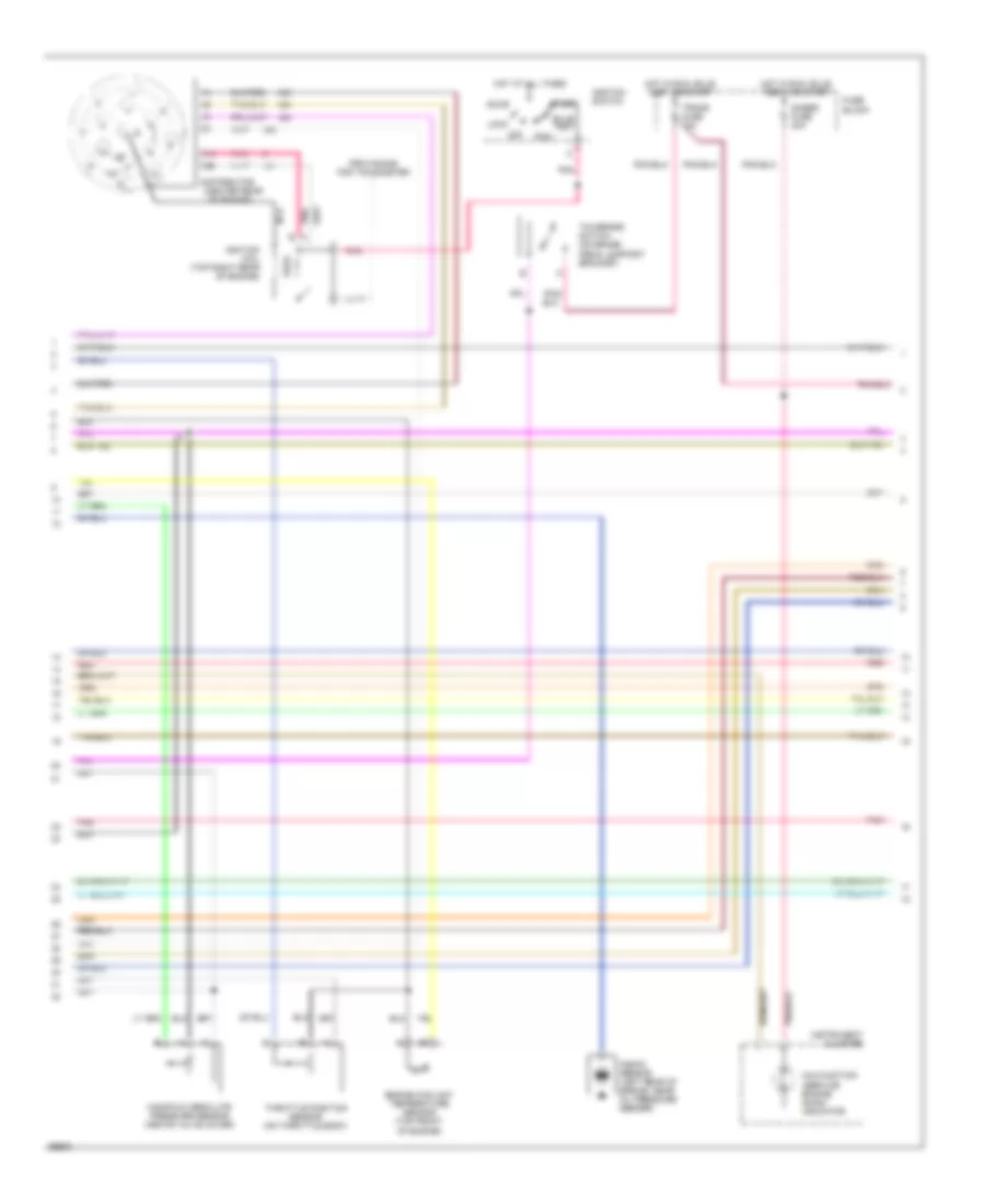
4.3L (VIN Z), Engine Performance Wiring Diagrams, A/T Commercial Chassis (2 of 3) for GMC Vandura G1994 2500
List of elements for 4.3L (VIN Z), Engine Performance Wiring Diagrams, A/T Commercial Chassis (2 of 3) for GMC Vandura G1994 2500:
- (center rear
- 4.3l and 7.4l
- 5.7l
- Accy
- Alt fuse 20a
- Bulb test
- Distributor
- Engine coolant temperature sensor (top front of engine)
- Fuse block
- G125 (at generator bracket)
- Hot at all times
- Hot in run, bulb test, or start
- Ignition coil (top right rear of engine)
- Ignition switch
- Instrument cluster
- Knock sensor (left rear of engine, near oil pressure sender)
- Knock sensor module (top right side of engine)
- Lock
- Malfunction (service engine soon) indicator
- Manifold absolute pressure sensor (above valve cover)
- Nca
- Of engine)
- Off
- Pnk
- Pnk b
- Pnk/
- Provisions for tachometer
- Red
- Run
- Start
- Tcc/brake switch (on brake pedal support bracket)
- Throttle position sensor (on throttle body)
- Trans fuse 10a
4.3L (VIN Z), Engine Performance Wiring Diagrams, A/T Commercial Chassis (3 of 3) for GMC Vandura G1994 2500
List of elements for 4.3L (VIN Z), Engine Performance Wiring Diagrams, A/T Commercial Chassis (3 of 3) for GMC Vandura G1994 2500:
- 1-2 shift soleniod
- 2-3 shift soleniod
- 4.3l
- 5.7l and 7.4l
- Bh conn pin h2
- Data link connector (behind left side of shipping panel)
- Ecm-bat fuse 10a
- Electronic 4-speed automatic overdrive transmission
- Fuel pump and sender (in fuel tank)
- Fuel pump oil pressure switch (top rear of engine)
- Fuel pump prime connector (no location available)
- Fuel pump relay (lower left side of shipping panel)
- Fuse block
- G125 (at generator bracket)
- G125 (front of engine near thermostat)
- G402 (left frame rail near fuel tank)
- Heated oxygen sensor (in exhaust manifold)
- Hot at all times
- Nca
- Oxygen sensor (in exhaust manifold)
- Pnk
- Pressure control solenoid
- Range mode selector
- Red
- Torque converter clutch solenoid
- Trans- mission temp sensor
- Vehicle speed sensor (left rear of transmission)
- Vehicle speed sensor buffer (behind right side of i/p)
4.3L (VIN Z), Engine Performance Wiring Diagrams, M/T Commercial Chassis (1 of 2) for GMC Vandura G1994 2500
List of elements for 4.3L (VIN Z), Engine Performance Wiring Diagrams, M/T Commercial Chassis (1 of 2) for GMC Vandura G1994 2500:
- 5 volt ref
- A/c signal
- A10
- A11
- A12
- Air conditioning system
- B10
- B11
- B12
- Battery feed
- C10
- C11
- C12
- C13
- C14
- C15
- C16
- C250
- C251
- Crank signal
- Crnk fuse 10a
- D10
- D11
- D12
- D13
- D14
- D15
- D16
- Data link connector (behind left side of shipping panel)
- Diagnostic test terminal
- Ecm bat fuse 10a
- Ecm-crnk fuse 10a
- Ect signal
- Egr control
- Engine coolant temperature sensor (top front of engine)
- Fuel pump relay
- Fuel pump signal
- Fuse block
- G125 (front of engine)
- Hot at all times
- Hot in run, bulb test, or start
- Hot in start
- Iac a high
- Iac a low
- Iac b high
- Iac b low
- Ic bypass
- Ic control
- Ic reference high
- Ic reference low
- Idle air control actuator (top rear of engine)
- Ign ecm fused
- Inj fuse 7.5a
- Injector 1 control
- Injector 2 control
- Knock signal
- Malfunction indicator lamp
- Manifold absolute pressure sensor (top rear of engine)
- Map sensor ground
- Map signal
- Oxygen sensor ground
- Oxygen sensor signal
- Powertrain control module (left side of shipping panel)
- Red
- Sensor ground
- Serial data
- System ground
- Tan
- Throttle body fuel injector #1 (top of throttle body unit)
- Throttle body fuel injector #2 (top of throttle body unit)
- Throttle position sensor (top right side of engine)
- Tp signal
- Vss signal
4.3L (VIN Z), Engine Performance Wiring Diagrams, M/T Commercial Chassis (2 of 2) for GMC Vandura G1994 2500
List of elements for 4.3L (VIN Z), Engine Performance Wiring Diagrams, M/T Commercial Chassis (2 of 2) for GMC Vandura G1994 2500:
- (top rear
- 4.3l
- 5.7l
- Accy
- Alt fuse 20a
- Bulb test
- Distributor
- Egr electronic vacuum regulator solenoid valve (top right front of engine)
- Egr solenoid (top right side of engine)
- For tachometer
- Fuel pump and sender (in fuel tank)
- Fuel pump oil pressure switch (top rear of engine)
- Fuel pump prime connector
- Fuel pump relay (lower left side of shipping panel)
- Fuse block
- G125 (at generator bracket)
- G125 (front of engine
- G125 (front of engine)
- G402 (along left frame rail near fuel tank)
- G402 (left frame rail near fuel tank)
- Heated oxygen sensor (in exhaust manifold)
- Hot at all times
- Hot in run, bulb test, or start
- Ignition coil (top of engine near distributor)
- Ignition switch
- Instrument cluster
- Knock sensor (right side of engine)
- Knock sensor module (top right side of engine)
- Lock
- Malfunction (service engine soon) indicator
- Nca
- Of engine)
- Off
- Oxygen sensor (in exhaust manifold)
- Pnk
- Pnk b
- Provisions
- Red
- Run
- Start
- Vehicle speed sensor (left rear of transmission)
- Vehicle speed sensor buffer (behind right side of i/p)
5.0L
5.0L (VIN H), Engine Performance Wiring Diagrams, 4L60E A/T (1 of 3) for GMC Vandura G1994 2500
List of elements for 5.0L (VIN H), Engine Performance Wiring Diagrams, 4L60E A/T (1 of 3) for GMC Vandura G1994 2500:
- (front of engine, near thermostat)
- 12v battery
- 12v ignition
- 5v return a
- 5v return b
- 5v sensor ref
- A/c on signal in
- A10
- A11
- A12
- A13
- A14
- A15
- A16
- Air condition- ing system
- B10
- B11
- B12
- B13
- B14
- B15
- B16
- Brake sw to pcm
- C308
- C311
- Cruise control system
- Cruise ind reg grd
- Distributor ref hi
- Distributor ref lo
- Dlc
- Dlc serial data
- E10
- E11
- E12
- E13
- E14
- E15
- E16
- Ecm b fuse 10a
- Ecm i fuse 10a
- Egr valve solenoid
- Elec fuel pump in
- Engine coolant temp sens
- Exhaust gas recirculation valve solenoid (top right side of engine)
- F10
- F11
- F12
- F13
- F14
- F15
- F16
- Fuel pump relay drive
- Fuse block
- G117 (rear of engine, near distributor)
- G125
- Hot at all times
- Hot in run, bulb test, or start
- Idle air control unit (right side of throttle body)
- Ignition bypass
- Ignition control (ic)
- Knock sensor in
- Lo side inj a
- Lo side inj b
- Map sensor in
- Mil indicator ctrl
- Oxygen sensor hi
- Oxygen sensor lo
- Pcm to trans temp sensor
- Pcm trans force mtr hi
- Pcm trans force mtr lo
- Pcm trans range a
- Pcm trans range b
- Pcm trans range c
- Pcm trans shift sol a
- Pcm trans shift sol b
- Pnk
- Powertrain control module (under driver's seat)
- Red
- Stepper coil a hi
- Stepper coil a lo
- Stepper coil b hi
- Stepper coil b lo
- System ground
- Tan
- Tcc clutch ctrl
- Throttle body fuel injector #1 (top of throttle body unit)
- Throttle body fuel injector #2 (top of throttle body unit)
- Throttle position signal
- Trans fuse 15a
- Trans shift 2/3 solenoid
- Vss buffer signal
5.0L (VIN H), Engine Performance Wiring Diagrams, 4L60E A/T (2 of 3) for GMC Vandura G1994 2500
List of elements for 5.0L (VIN H), Engine Performance Wiring Diagrams, 4L60E A/T (2 of 3) for GMC Vandura G1994 2500:
- (center rear
- Accy
- Auxiliary fuse block
- Brake fuse 20a
- Bulb test
- C11
- C12
- Distributor
- Engine coolant temperature sensor (on intake manifold)
- Fuse block
- Gages fuse 20a
- Hot at all times
- Hot in run
- Hot in run, bulb test, or start
- Ignition coil (top right rear of engine)
- Ignition switch
- Instrument cluster
- Knock sensor (left rear of engine, near oil pressure sender)
- Lock
- Malfunction (service engine soon) indicator
- Manifold absolute pressure sensor (above valve cover)
- Nca
- Of engine)
- Off
- Pnk
- Pnk b
- Pnk/
- Red
- Run
- Start
- Tachometer test lead
- Tcc/brake switch (on brake pedal support bracket)
- Throttle position sensor (on throttle body)
5.0L (VIN H), Engine Performance Wiring Diagrams, 4L60E A/T (3 of 3) for GMC Vandura G1994 2500
List of elements for 5.0L (VIN H), Engine Performance Wiring Diagrams, 4L60E A/T (3 of 3) for GMC Vandura G1994 2500:
- 1-2 shift soleniod
- 2-3 shift soleniod
- 3-2 shift solenoid
- 4.3l
- All except 4.3l
- Auxiliary fuse block
- B/h conn pin b3
- Data link connector (behind left side of i/p)
- Electronic 4-speed automatic overdrive transmission
- Fuel pump and sender
- Fuel pump fuse 20a
- Fuel pump oil pressure switch (top rear of engine)
- Fuel pump prime connector (no location available)
- Fuel pump relay (right front of cowl, above blower motor)
- Fuse block
- G125 (front of engine near thermostat)
- Heated oxygen sensor (4.3l only) (in exhaust y-pipe)
- Hot at all times
- Hot in run, bulb test, or start
- Nca
- Oxygen sensor (in exhaust manifold)
- Pnk
- Pressure control solenoid
- Range mode selector
- Red
- Torque converter clutch solenoid
- Trans fuse 10a
- Trans- mission temp sensor
- Vehicle speed sensor (left rear of transmission)
- Vehicle speed sensor buffer (on parking brake support bracket)
5.0L (VIN H), Engine Performance Wiring Diagrams, 4L80E A/T (1 of 3) for GMC Vandura G1994 2500
List of elements for 5.0L (VIN H), Engine Performance Wiring Diagrams, 4L80E A/T (1 of 3) for GMC Vandura G1994 2500:
- 1-2 shift solenoid control
- 2-3 shift solenoid control
- 4.3l and 5.7l
- 4.3l and 5.7l only
- 5.7l hd
- 5.7l hd only
- 7.4l
- 7.4l only
- A/c signal
- A10
- A11
- A12
- A13
- A14
- A15
- A16
- Air condition- ing system
- B10
- B11
- B12
- B13
- B14
- B15
- B16
- Battery feed
- Brake signal
- C308
- C311
- Canister purge control
- Cruise control system
- Cruise signal
- Diagnostic test
- E10
- E11
- E12
- E13
- E14
- E15
- E16
- Ecm b fuse 10a
- Ecm i fuse 10a
- Ect signal
- Egr control
- Egr electonic vacuum regulator soleniod valve (top right side of engine)
- Egr pintle position signal
- Evaporative canister purge control solenoid (top right front of engine)
- Exhaust gas recirculation valve solenoid (top right side of engine)
- F10
- F11
- F12
- F13
- F14
- F15
- F16
- Fuel pump relay ctrl
- Fuel pump signal
- Fuse block
- G117 (rear of engine, near distributor)
- G125 (front of engine near thermostat)
- Governor control
- Hot at all times
- Hot in run, bulb test, or start
- Iac "a" high
- Iac "a" low
- Iac "b" high
- Iac "b" low
- Ic bypass
- Ic control
- Ic ref hi
- Ic ref lo
- Idle air control unit (right side of throttle body)
- Idle speed actuator control solenoid (no location available)
- Idle speed actuator ctrl
- Ignition feed
- Injector 1 control
- Injector 2 control
- Input speed signal high
- Input speed signal low
- Knock signal
- Linear egr vacuum regulator solenoid valve (above right rocker cover)
- Map signal
- Mil control
- Nca
- O2s 5.7l & 7.4l h2os 4.3l
- Oxygen sensor (in exhaust manifold)
- Oxygen sensor ground
- Pcs high
- Pcs low
- Pnk
- Powertrain control module (under driver's seat)
- Range signal a
- Range signal b
- Range signal c
- Red
- Sensor ground
- Sensor ref
- Serial data
- System ground
- Tan
- Tcc solenoid control
- Tft signal
- Throttle body fuel injector #1 (top of throttle body unit)
- Throttle body fuel injector #2 (top of throttle body unit)
- Tp reference
- Tp sensor signal
- Trans fuse 15a
- Transmission input speed sensor (no location)
- Transmission output speed
- Vss signal
5.0L (VIN H), Engine Performance Wiring Diagrams, 4L80E A/T (2 of 3) for GMC Vandura G1994 2500
List of elements for 5.0L (VIN H), Engine Performance Wiring Diagrams, 4L80E A/T (2 of 3) for GMC Vandura G1994 2500:
- (center rear
- Accy
- Auxiliary fuse block
- Brake fuse 20a
- Bulb test
- C11
- C12
- Distributor
- Engine coolant temperature sensor (on intake manifold)
- Fuse block
- Gages fuse 20a
- Hot at all times
- Hot in run
- Hot in run, bulb test, or start
- Ignition coil (top right rear of engine)
- Ignition switch
- Instrument cluster
- Knock sensor (left rear of engine, near oil pressure sender)
- Lock
- Malfunction (service engine soon) indicator
- Manifold absolute pressure sensor (above valve cover)
- Nca
- Of engine)
- Off
- Pnk
- Pnk b
- Pnk/
- Red
- Run
- Start
- Tachometer test lead
- Tcc/brake switch (on brake pedal support bracket)
- Throttle position sensor (on throttle body)
5.0L (VIN H), Engine Performance Wiring Diagrams, 4L80E A/T (3 of 3) for GMC Vandura G1994 2500
List of elements for 5.0L (VIN H), Engine Performance Wiring Diagrams, 4L80E A/T (3 of 3) for GMC Vandura G1994 2500:
- 1-2 shift soleniod
- 2-3 shift soleniod
- 7.4l only
- Auxiliary fuse block
- B/h conn pin b3
- Data link connector (behind left side of i/p)
- Electronic 4-speed automatic overdrive transmission
- Fuel pump and sender
- Fuel pump fuse 20a
- Fuel pump oil pressure switch (top rear of engine)
- Fuel pump prime connector (no location available)
- Fuel pump relay (right front of cowl, above blower motor)
- Fuse block
- G125 (front of engine near thermostat)
- G125 (front of engine, near thermostat)
- Governor control module (left top front of engine)
- Hot at all times
- Hot in run, bulb test, or start
- In-line fuse 10a (top center rear of engine)
- Pnk
- Pressure control solenoid
- Range mode selector
- Red
- Throttle body governor (left side of throttle body)
- Torque converter clutch solenoid
- Trans fuse 10a
- Trans- mission temp sensor
- Vehicle speed sensor (left rear of transmission)
- Vehicle speed sensor buffer (on parking brake support bracket)
5.7L
5.7L (VIN K), Engine Performance Wiring Diagrams, 4L60E A/T (1 of 3) for GMC Vandura G1994 2500
List of elements for 5.7L (VIN K), Engine Performance Wiring Diagrams, 4L60E A/T (1 of 3) for GMC Vandura G1994 2500:
- (front of engine, near thermostat)
- 12v battery
- 12v ignition
- 5v return a
- 5v return b
- 5v sensor ref
- A/c on signal in
- A10
- A11
- A12
- A13
- A14
- A15
- A16
- Air condition- ing system
- B10
- B11
- B12
- B13
- B14
- B15
- B16
- Brake sw to pcm
- C308
- C311
- Cruise control system
- Cruise ind reg grd
- Distributor ref hi
- Distributor ref lo
- Dlc
- Dlc serial data
- E10
- E11
- E12
- E13
- E14
- E15
- E16
- Ecm b fuse 10a
- Ecm i fuse 10a
- Egr valve solenoid
- Elec fuel pump in
- Engine coolant temp sens
- Exhaust gas recirculation valve solenoid (top right side of engine)
- F10
- F11
- F12
- F13
- F14
- F15
- F16
- Fuel pump relay drive
- Fuse block
- G117 (rear of engine, near distributor)
- G125
- Hot at all times
- Hot in run, bulb test, or start
- Idle air control unit (right side of throttle body)
- Ignition bypass
- Ignition control (ic)
- Knock sensor in
- Lo side inj a
- Lo side inj b
- Map sensor in
- Mil indicator ctrl
- Oxygen sensor hi
- Oxygen sensor lo
- Pcm to trans temp sensor
- Pcm trans force mtr hi
- Pcm trans force mtr lo
- Pcm trans range a
- Pcm trans range b
- Pcm trans range c
- Pcm trans shift sol a
- Pcm trans shift sol b
- Pnk
- Powertrain control module (under driver's seat)
- Red
- Stepper coil a hi
- Stepper coil a lo
- Stepper coil b hi
- Stepper coil b lo
- System ground
- Tan
- Tcc clutch ctrl
- Throttle body fuel injector #1 (top of throttle body unit)
- Throttle body fuel injector #2 (top of throttle body unit)
- Throttle position signal
- Trans fuse 15a
- Trans shift 2/3 solenoid
- Vss buffer signal
5.7L (VIN K), Engine Performance Wiring Diagrams, 4L60E A/T (2 of 3) for GMC Vandura G1994 2500
List of elements for 5.7L (VIN K), Engine Performance Wiring Diagrams, 4L60E A/T (2 of 3) for GMC Vandura G1994 2500:
- (center rear
- Accy
- Auxiliary fuse block
- Brake fuse 20a
- Bulb test
- C11
- C12
- Distributor
- Engine coolant temperature sensor (on intake manifold)
- Fuse block
- Gages fuse 20a
- Hot at all times
- Hot in run
- Hot in run, bulb test, or start
- Ignition coil (top right rear of engine)
- Ignition switch
- Instrument cluster
- Knock sensor (left rear of engine, near oil pressure sender)
- Lock
- Malfunction (service engine soon) indicator
- Manifold absolute pressure sensor (above valve cover)
- Nca
- Of engine)
- Off
- Pnk
- Pnk b
- Pnk/
- Red
- Run
- Start
- Tachometer test lead
- Tcc/brake switch (on brake pedal support bracket)
- Throttle position sensor (on throttle body)
5.7L (VIN K), Engine Performance Wiring Diagrams, 4L60E A/T (3 of 3) for GMC Vandura G1994 2500
List of elements for 5.7L (VIN K), Engine Performance Wiring Diagrams, 4L60E A/T (3 of 3) for GMC Vandura G1994 2500:
- 1-2 shift soleniod
- 2-3 shift soleniod
- 3-2 shift solenoid
- 4.3l
- All except 4.3l
- Auxiliary fuse block
- B/h conn pin b3
- Data link connector (behind left side of i/p)
- Electronic 4-speed automatic overdrive transmission
- Fuel pump and sender
- Fuel pump fuse 20a
- Fuel pump oil pressure switch (top rear of engine)
- Fuel pump prime connector (no location available)
- Fuel pump relay (right front of cowl, above blower motor)
- Fuse block
- G125 (front of engine near thermostat)
- Heated oxygen sensor (4.3l only) (in exhaust y-pipe)
- Hot at all times
- Hot in run, bulb test, or start
- Nca
- Oxygen sensor (in exhaust manifold)
- Pnk
- Pressure control solenoid
- Range mode selector
- Red
- Torque converter clutch solenoid
- Trans fuse 10a
- Trans- mission temp sensor
- Vehicle speed sensor (left rear of transmission)
- Vehicle speed sensor buffer (on parking brake support bracket)
5.7L (VIN K), Engine Performance Wiring Diagrams, 4L80E A/T (1 of 3) for GMC Vandura G1994 2500
List of elements for 5.7L (VIN K), Engine Performance Wiring Diagrams, 4L80E A/T (1 of 3) for GMC Vandura G1994 2500:
- 1-2 shift solenoid control
- 2-3 shift solenoid control
- 4.3l and 5.7l
- 4.3l and 5.7l only
- 5.7l hd
- 5.7l hd only
- 7.4l
- 7.4l only
- A/c signal
- A10
- A11
- A12
- A13
- A14
- A15
- A16
- Air condition- ing system
- B10
- B11
- B12
- B13
- B14
- B15
- B16
- Battery feed
- Brake signal
- C308
- C311
- Canister purge control
- Cruise control system
- Cruise signal
- Diagnostic test
- E10
- E11
- E12
- E13
- E14
- E15
- E16
- Ecm b fuse 10a
- Ecm i fuse 10a
- Ect signal
- Egr control
- Egr electonic vacuum regulator soleniod valve (top right side of engine)
- Egr pintle position signal
- Evaporative canister purge control solenoid (top right front of engine)
- Exhaust gas recirculation valve solenoid (top right side of engine)
- F10
- F11
- F12
- F13
- F14
- F15
- F16
- Fuel pump relay ctrl
- Fuel pump signal
- Fuse block
- G117 (rear of engine, near distributor)
- G125 (front of engine near thermostat)
- Governor control
- Hot at all times
- Hot in run, bulb test, or start
- Iac "a" high
- Iac "a" low
- Iac "b" high
- Iac "b" low
- Ic bypass
- Ic control
- Ic ref hi
- Ic ref lo
- Idle air control unit (right side of throttle body)
- Idle speed actuator control solenoid (no location available)
- Idle speed actuator ctrl
- Ignition feed
- Injector 1 control
- Injector 2 control
- Input speed signal high
- Input speed signal low
- Knock signal
- Linear egr vacuum regulator solenoid valve (above right rocker cover)
- Map signal
- Mil control
- Nca
- O2s 5.7l & 7.4l h2os 4.3l
- Oxygen sensor (in exhaust manifold)
- Oxygen sensor ground
- Pcs high
- Pcs low
- Pnk
- Powertrain control module (under driver's seat)
- Range signal a
- Range signal b
- Range signal c
- Red
- Sensor ground
- Sensor ref
- Serial data
- System ground
- Tan
- Tcc solenoid control
- Tft signal
- Throttle body fuel injector #1 (top of throttle body unit)
- Throttle body fuel injector #2 (top of throttle body unit)
- Tp reference
- Tp sensor signal
- Trans fuse 15a
- Transmission input speed sensor (no location)
- Transmission output speed
- Vss signal
5.7L (VIN K), Engine Performance Wiring Diagrams, 4L80E A/T (2 of 3) for GMC Vandura G1994 2500
List of elements for 5.7L (VIN K), Engine Performance Wiring Diagrams, 4L80E A/T (2 of 3) for GMC Vandura G1994 2500:
- (center rear
- Accy
- Auxiliary fuse block
- Brake fuse 20a
- Bulb test
- C11
- C12
- Distributor
- Engine coolant temperature sensor (on intake manifold)
- Fuse block
- Gages fuse 20a
- Hot at all times
- Hot in run
- Hot in run, bulb test, or start
- Ignition coil (top right rear of engine)
- Ignition switch
- Instrument cluster
- Knock sensor (left rear of engine, near oil pressure sender)
- Lock
- Malfunction (service engine soon) indicator
- Manifold absolute pressure sensor (above valve cover)
- Nca
- Of engine)
- Off
- Pnk
- Pnk b
- Pnk/
- Red
- Run
- Start
- Tachometer test lead
- Tcc/brake switch (on brake pedal support bracket)
- Throttle position sensor (on throttle body)
5.7L (VIN K), Engine Performance Wiring Diagrams, 4L80E A/T (3 of 3) for GMC Vandura G1994 2500
List of elements for 5.7L (VIN K), Engine Performance Wiring Diagrams, 4L80E A/T (3 of 3) for GMC Vandura G1994 2500:
- 1-2 shift soleniod
- 2-3 shift soleniod
- 7.4l only
- Auxiliary fuse block
- B/h conn pin b3
- Data link connector (behind left side of i/p)
- Electronic 4-speed automatic overdrive transmission
- Fuel pump and sender
- Fuel pump fuse 20a
- Fuel pump oil pressure switch (top rear of engine)
- Fuel pump prime connector (no location available)
- Fuel pump relay (right front of cowl, above blower motor)
- Fuse block
- G125 (front of engine near thermostat)
- G125 (front of engine, near thermostat)
- Governor control module (left top front of engine)
- Hot at all times
- Hot in run, bulb test, or start
- In-line fuse 10a (top center rear of engine)
- Pnk
- Pressure control solenoid
- Range mode selector
- Red
- Throttle body governor (left side of throttle body)
- Torque converter clutch solenoid
- Trans fuse 10a
- Trans- mission temp sensor
- Vehicle speed sensor (left rear of transmission)
- Vehicle speed sensor buffer (on parking brake support bracket)
5.7L (VIN K), Engine Performance Wiring Diagrams, A/T Commercial Chassis and Motorhome (1 of 3) for GMC Vandura G1994 2500
List of elements for 5.7L (VIN K), Engine Performance Wiring Diagrams, A/T Commercial Chassis and Motorhome (1 of 3) for GMC Vandura G1994 2500:
- 1-2 shift solenoid control
- 2-3 shift solenoid control
- 4.3l
- 4.3l only
- 5.7l
- 5.7l only
- 7.4l
- 7.4l only
- A/c signal
- A10
- A11
- A12
- A13
- A14
- A15
- A16
- Air condition- ing system
- B10
- B11
- B12
- B13
- B14
- B15
- B16
- Battery feed
- Brake signal
- C308
- C311
- Canister purge control
- Cruise control system
- Cruise signal
- Diagnostic test
- E10
- E11
- E12
- E13
- E14
- E15
- E16
- Ecm bat fuse 10a
- Ecm crnk fuse 10a
- Ect signal
- Egr control
- Egr electonic vacuum regulator soleniod valve (top right front of engine)
- Egr pintle position signal
- Evaporative canister purge control solenoid (top right side of engine)
- Exhaust gas recirculation valve solenoid (top right side of engine)
- F10
- F11
- F12
- F13
- F14
- F15
- F16
- Fuel pump relay ctrl
- Fuel pump signal
- Fuse block
- G125 (front of engine)
- Governor control
- Hot at all times
- Hot in run, bulb test, or start
- Iac "a" high
- Iac "a" low
- Iac "b" high
- Iac "b" low
- Ic bypass
- Ic control
- Ic ref hi
- Ic ref lo
- Idle air control actuator (top rear of engine)
- Idle speed actuator control solenoid (no location available)
- Idle speed actuator ctrl
- Ignition feed
- Inj fuse 7.5a
- Injector 1 control
- Injector 2 control
- Input speed signal high
- Input speed signal low
- Knock sensor input
- Knock signal
- Linear egr vacuum regulator solenoid valve (top front of engine)
- Map signal
- Mil control
- O2s 5.7l & 7.4l h2os 4.3l
- Oxygen sensor ground
- Pcs high
- Pcs low
- Pnk
- Powertrain control module (left side of shipping panel)
- Range signal a
- Range signal b
- Range signal c
- Red
- Sensor ground
- Sensor ref
- Serial data
- System ground
- Tan
- Tcc solenoid control
- Tft signal
- Throttle body fuel injector #1 (top of throttle body unit)
- Throttle body fuel injector #2 (top of throttle body unit)
- Tp reference
- Tp sensor signal
- Transmission input speed sensor (no location)
- Transmission output speed
- Vss signal
5.7L (VIN K), Engine Performance Wiring Diagrams, A/T Commercial Chassis and Motorhome (2 of 3) for GMC Vandura G1994 2500
List of elements for 5.7L (VIN K), Engine Performance Wiring Diagrams, A/T Commercial Chassis and Motorhome (2 of 3) for GMC Vandura G1994 2500:
- (center rear
- 4.3l and 7.4l
- 5.7l
- Accy
- Alt fuse 20a
- Bulb test
- Distributor
- Engine coolant temperature sensor (top front of engine)
- Fuse block
- G125 (at generator bracket)
- Hot at all times
- Hot in run, bulb test, or start
- Ignition coil (top right rear of engine)
- Ignition switch
- Instrument cluster
- Knock sensor (left rear of engine, near oil pressure sender)
- Knock sensor module (top right side of engine)
- Lock
- Malfunction (service engine soon) indicator
- Manifold absolute pressure sensor (above valve cover)
- Nca
- Of engine)
- Off
- Pnk
- Pnk b
- Pnk/
- Provisions for tachometer
- Red
- Run
- Start
- Tcc/brake switch (on brake pedal support bracket)
- Throttle position sensor (on throttle body)
- Trans fuse 10a
5.7L (VIN K), Engine Performance Wiring Diagrams, A/T Commercial Chassis and Motorhome (3 of 3) for GMC Vandura G1994 2500
List of elements for 5.7L (VIN K), Engine Performance Wiring Diagrams, A/T Commercial Chassis and Motorhome (3 of 3) for GMC Vandura G1994 2500:
- 1-2 shift soleniod
- 2-3 shift soleniod
- 4.3l
- 5.7l and 7.4l
- Bh conn pin h2
- Data link connector (behind left side of shipping panel)
- Ecm-bat fuse 10a
- Electronic 4-speed automatic overdrive transmission
- Fuel pump and sender (in fuel tank)
- Fuel pump oil pressure switch (top rear of engine)
- Fuel pump prime connector (no location available)
- Fuel pump relay (lower left side of shipping panel)
- Fuse block
- G125 (at generator bracket)
- G125 (front of engine near thermostat)
- G402 (left frame rail near fuel tank)
- Heated oxygen sensor (in exhaust manifold)
- Hot at all times
- Nca
- Oxygen sensor (in exhaust manifold)
- Pnk
- Pressure control solenoid
- Range mode selector
- Red
- Torque converter clutch solenoid
- Trans- mission temp sensor
- Vehicle speed sensor (left rear of transmission)
- Vehicle speed sensor buffer (behind right side of i/p)
5.7L (VIN K), Engine Performance Wiring Diagrams, A/T P/G Cutaway (1 of 3) for GMC Vandura G1994 2500
List of elements for 5.7L (VIN K), Engine Performance Wiring Diagrams, A/T P/G Cutaway (1 of 3) for GMC Vandura G1994 2500:
- 1-2 shift solenoid control
- 2-3 shift solenoid control
- 5.7l
- 5.7l only
- 7.4l
- 7.4l only
- A/c signal
- A10
- A11
- A12
- A13
- A14
- A15
- A16
- Air condition- ing system
- B10
- B11
- B12
- B13
- B14
- B15
- B16
- Battery feed
- Brake signal
- C308
- C311
- Canister purge control
- Diagnostic test
- E10
- E11
- E12
- E13
- E14
- E15
- E16
- Ecm-i fuse 20a
- Ect signal
- Egr control
- Egr pintle position signal
- Evaporative canister purge control solenoid (top right side of engine)
- Exhaust gas recirculation valve solenoid (top right side of engine)
- F10
- F11
- F12
- F13
- F14
- F15
- F16
- Fuel pump relay ctrl
- Fuel pump signal
- Fuse block
- G102 (right front of engine)
- G125 (at generator bracket)
- G125 (front of engine)
- Hot in run, bulb test, or start
- Iac "a" high
- Iac "a" low
- Iac "b" high
- Iac "b" low
- Ic bypass
- Ic control
- Ic ref hi
- Ic ref lo
- Idle air control actuator (top rear of engine)
- Idle speed actuator control solenoid (no location available)
- Idle speed actuator ctrl
- Ignition feed
- Injector 1 control
- Injector 2 control
- Input speed signal high
- Input speed signal low
- Knock signal
- Linear egr vacuum regulator solenoid valve (top front of engine)
- Map signal
- Mil control
- Nca
- O2s
- Oxygen sensor (in exhaust manifold)
- Oxygen sensor ground
- Pcs high
- Pcs low
- Pnk
- Powertrain control module (left side of shipping panel)
- Range signal a
- Range signal b
- Range signal c
- Red
- Sensor ground
- Sensor ref
- Serial data
- System ground
- Tan
- Tcc solenoid control
- Tft signal
- Throttle body fuel injector #1 (top of throttle body unit)
- Throttle body fuel injector #2 (top of throttle body unit)
- Tp reference
- Tp sensor signal
- Transmission input speed sensor (left side of transmission)
- Transmission output speed
- Vss signal
5.7L (VIN K), Engine Performance Wiring Diagrams, A/T P/G Cutaway (2 of 3) for GMC Vandura G1994 2500
List of elements for 5.7L (VIN K), Engine Performance Wiring Diagrams, A/T P/G Cutaway (2 of 3) for GMC Vandura G1994 2500:
- (center rear
- Accy
- Bulb test
- Distributor
- Engine coolant temperature sensor (top front of engine)
- Fuse block
- Gages fuse 20a
- Hot at all times
- Hot in run, bulb test, or start
- Ignition coil (top right rear of engine)
- Ignition switch
- Instrument cluster
- Knock sensor (left rear of engine, near oil pressure sender)
- Lock
- Malfunction (service engine soon) indicator
- Manifold absolute pressure sensor (above valve cover)
- Nca
- Of engine)
- Off
- Pnk
- Pnk b
- Pnk/
- Provisions for tachometer
- Red
- Run
- Start
- Tcc/brake switch (on brake pedal support bracket)
- Throttle position sensor (on throttle body)
- Trans fuse 10a
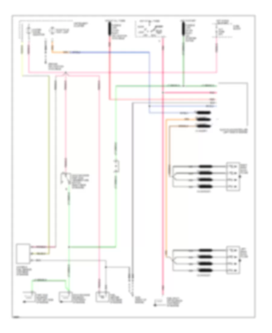
5.7L (VIN K), Engine Performance Wiring Diagrams, A/T P/G Cutaway (3 of 3) for GMC Vandura G1994 2500
List of elements for 5.7L (VIN K), Engine Performance Wiring Diagrams, A/T P/G Cutaway (3 of 3) for GMC Vandura G1994 2500:
- 1-2 shift soleniod
- 2-3 shift soleniod
- Bh conn pin h2
- Data link connector (behind left side of shipping panel)
- Electronic 4-speed automatic overdrive transmission
- Fuel pump and sender (in fuel tank)
- Fuel pump fuse 20a
- Fuel pump oil pressure switch (top rear of engine)
- Fuel pump prime connector (top of cowl)
- Fuel pump relay (lower left side of shipping panel)
- Fuse block
- G125 (at generator bracket)
- G125 (front of engine near thermostat)
- G402 (left frame rail near fuel tank)
- Hot at all times
- Nca
- Pnk
- Pressure control solenoid
- Range mode selector
- Red
- Torque converter clutch solenoid
- Trans- mission temp sensor
- Vehicle speed sensor (left rear of transmission)
- Vehicle speed sensor buffer (behind right side of i/p)
5.7L (VIN K), Engine Performance Wiring Diagrams, M/T Commercial Chassis (1 of 2) for GMC Vandura G1994 2500
List of elements for 5.7L (VIN K), Engine Performance Wiring Diagrams, M/T Commercial Chassis (1 of 2) for GMC Vandura G1994 2500:
- 5 volt ref
- A/c signal
- A10
- A11
- A12
- Air conditioning system
- B10
- B11
- B12
- Battery feed
- C10
- C11
- C12
- C13
- C14
- C15
- C16
- C250
- C251
- Crank signal
- Crnk fuse 10a
- D10
- D11
- D12
- D13
- D14
- D15
- D16
- Data link connector (behind left side of shipping panel)
- Diagnostic test terminal
- Ecm bat fuse 10a
- Ecm-crnk fuse 10a
- Ect signal
- Egr control
- Engine coolant temperature sensor (top front of engine)
- Fuel pump relay
- Fuel pump signal
- Fuse block
- G125 (front of engine)
- Hot at all times
- Hot in run, bulb test, or start
- Hot in start
- Iac a high
- Iac a low
- Iac b high
- Iac b low
- Ic bypass
- Ic control
- Ic reference high
- Ic reference low
- Idle air control actuator (top rear of engine)
- Ign ecm fused
- Inj fuse 7.5a
- Injector 1 control
- Injector 2 control
- Knock signal
- Malfunction indicator lamp
- Manifold absolute pressure sensor (top rear of engine)
- Map sensor ground
- Map signal
- Oxygen sensor ground
- Oxygen sensor signal
- Powertrain control module (left side of shipping panel)
- Red
- Sensor ground
- Serial data
- System ground
- Tan
- Throttle body fuel injector #1 (top of throttle body unit)
- Throttle body fuel injector #2 (top of throttle body unit)
- Throttle position sensor (top right side of engine)
- Tp signal
- Vss signal
5.7L (VIN K), Engine Performance Wiring Diagrams, M/T Commercial Chassis (2 of 2) for GMC Vandura G1994 2500
List of elements for 5.7L (VIN K), Engine Performance Wiring Diagrams, M/T Commercial Chassis (2 of 2) for GMC Vandura G1994 2500:
- (top rear
- 4.3l
- 5.7l
- Accy
- Alt fuse 20a
- Bulb test
- Distributor
- Egr electronic vacuum regulator solenoid valve (top right front of engine)
- Egr solenoid (top right side of engine)
- For tachometer
- Fuel pump and sender (in fuel tank)
- Fuel pump oil pressure switch (top rear of engine)
- Fuel pump prime connector
- Fuel pump relay (lower left side of shipping panel)
- Fuse block
- G125 (at generator bracket)
- G125 (front of engine
- G125 (front of engine)
- G402 (along left frame rail near fuel tank)
- G402 (left frame rail near fuel tank)
- Heated oxygen sensor (in exhaust manifold)
- Hot at all times
- Hot in run, bulb test, or start
- Ignition coil (top of engine near distributor)
- Ignition switch
- Instrument cluster
- Knock sensor (right side of engine)
- Knock sensor module (top right side of engine)
- Lock
- Malfunction (service engine soon) indicator
- Nca
- Of engine)
- Off
- Oxygen sensor (in exhaust manifold)
- Pnk
- Pnk b
- Provisions
- Red
- Run
- Start
- Vehicle speed sensor (left rear of transmission)
- Vehicle speed sensor buffer (behind right side of i/p)
6.5L
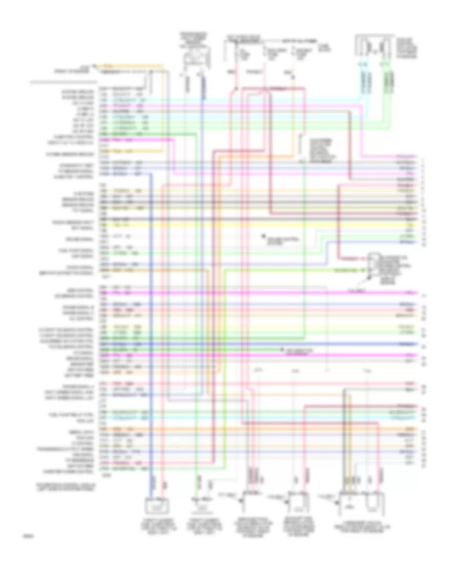
6.5L (VIN F), Engine Performance Wiring Diagrams (1 of 2) for GMC Vandura G1994 2500
List of elements for 6.5L (VIN F), Engine Performance Wiring Diagrams (1 of 2) for GMC Vandura G1994 2500:
- 1-2 shift sol
- 1-2 shift sol ctrl
- 2-3 shift sol
- 2-3 shift sol ctrl
- 5v ref
- A range mode selector
- Accelerator pedal position (app) module (top of accelerator bracket)
- App 1 sens 5v ref
- App 1 sens gnd
- App 1 sensor
- App 2 sens gnd
- App 2 sensor
- App 3 sens 5v ref
- App 3 sens gnd
- App 3 sensor
- App sens 1 sig
- App sens 2 sig
- B/h
- Baro sig
- Battery feed
- Block
- Boost sig
- C10
- C11
- C12
- C13
- C14
- C15
- C16
- Ckp sig
- Closure grd
- Control
- Cruise
- Cruise on/off sig
- D10
- D11
- D12
- D13
- D14
- D15
- D16
- Data link connector (no location available)
- E10
- E11
- E12
- E13
- E14
- E15
- E16
- Ect sig
- Electronic 4-speed automatic overdrive transmission
- Eng shut-off ctrl
- Engine coolant temperature (ect) sensor (right side of engine)
- Engine ground (no location available)
- Engine shut- off solenoid (top front of engine)
- F10
- F11
- F12
- F13
- F14
- F15
- F16
- Fuel inj ctrl
- Fuel inj sig
- Fuel solenoid (top front of engine)
- Fuel solenoid driver (top front of engine)
- Fuse
- Fusible link (no location available)
- Glow plug rly ctrl
- Hi resolution sig
- Hot at all times
- Hot in start or run
- Mil
- Optical sens 5v ref
- Optical sens cam sig
- Optical sens gnd
- Optical sensor and fuel temper- ature sensor (top front of engine)
- Pnk
- Powertrain control module (pcm) (no location available)
- Press ctrl sol
- Press ctrl sol lo
- Pressure control sol
- Range signal a
- Range signal b
- Range signal c
- Red
- Resume/accel sig
- Sensor gnd
- Serial data
- Set/coast sig
- System
- System gnd
- Tan
- Tcc brake sw
- Tcc sol
- Tcc sol ctrl (pwm)
- Trans fluid temp (tft) sensor
- Trans fluid temp sig
- Trans fuse 10a
- Trans input spd hi
- Trans input spd lo
- Trans output
- Trans output spd sig
- Transmission input speed sensor
- Vehicle speed sensor (left rear side of transmission)
- Vehicle speed sensor buffer (no location available)
- Vss
- Vss input
- Vss output
6.5L (VIN F), Engine Performance Wiring Diagrams (2 of 2) for GMC Vandura G1994 2500
List of elements for 6.5L (VIN F), Engine Performance Wiring Diagrams (2 of 2) for GMC Vandura G1994 2500:
- "service engine soon" lamp
- "service throttle" lamp
- (no location available)
- (on brake
- (upper rear of engine)
- A/c sig
- A10
- A11
- A12
- Air conditioning system
- All times
- Alt fuse 20a
- App 2 sens 5v ref
- App 3 sens sig
- B10
- B11
- B12
- Baro sensor (no location available)
- C red
- Crankshaft position sensor (top front of engine, inside
- Cruise ctrl brake sig
- Diagnostic request
- Ecm-crnk fuse 10a
- Fuel heater (no location available)
- Fuel pump (no location available)
- Fuel pump oil pressure switch
- Fuel pump relay (no location available)
- Fuel temp sig
- Fuse block
- Fusible link
- Fusible links
- Glow plug control relay (right rear top of engine)
- Glow plug sig
- Ground
- Ground (no location available)
- Hot at
- Hot at all times
- Hot in run, bulb test or start
- Hot in start or run
- Iat sig
- Ignition feed
- Injection pump)
- Injection timing stepper (its) motor (top front of engine)
- Instrument cluster
- Instrument clusters system
- Intake air temperature (iat) sensor (at front of engine)
- Its coil 1 hi
- Its coil 1 lo
- Its coil 2 hi
- Its coil 2 lo
- Left bank glow plugs
- Manifold absolute pressure sensor (no location available)
- Pedal
- Pnk
- Powertrain control module (pcm) (no location available)
- Red
- Right bank glow plugs
- Starting/ charging system
- Stop fuse 15a
- Stop lamp/ cruise control brake switch (on brake pedal support)
- Support)
- Switch
- Tan
- Tcc brake
- Wait lamp
- Wastegate sol ctrl
- Wastegate solenoid (left rear top of engine)
6.5L (VIN P), Engine Performance Wiring Diagrams (1 of 2) for GMC Vandura G1994 2500
List of elements for 6.5L (VIN P), Engine Performance Wiring Diagrams (1 of 2) for GMC Vandura G1994 2500:
- 1-2 shift sol
- 1-2 shift sol ctrl
- 2-3 shift sol
- 2-3 shift sol ctrl
- 3-2 shift sol
- 4 wheel drive low switch
- 5v ref
- A range mode selector
- Accelerator pedal position (app) module (top of accelerator bracket)
- Anti-lock brakes system
- App 1 sens 5v ref
- App 1 sens gnd
- App 1 sensor
- App 2 sens gnd
- App 2 sensor
- App 3 sens 5v ref
- App 3 sens gnd
- App 3 sensor
- App sens 1 sig
- App sens 2 sig
- B/h
- Battery feed
- C10
- C11
- C12
- C13
- C14
- C15
- C16
- Ckp sig
- Closure sig
- Cruise control system
- Cruise on/off sig
- D10
- D11
- D12
- D13
- D14
- D15
- D16
- Data link connector (under left side of i/p)
- E10
- E11
- E12
- E13
- E14
- E15
- E16
- Ecmb fuse 10a
- Ect sig
- Egr sol ctrl
- Electronic 4-speed automatic overdrive transmission
- Eng shut-off ctrl
- Engine coolant temperature (ect) sensor (right rear front of engine)
- Engine shut- off solenoid (top front of engine)
- F10
- F11
- F12
- F13
- F14
- F15
- F16
- Fpmp fuse 20a
- Fuel inj ctrl
- Fuel inj sig
- Fuel solenoid (top front of engine)
- Fuel solenoid driver (top front of engine)
- Fuse block
- Fwd low sw
- G117 (top right rear of engine)
- Glow plug rly ctrl
- Hi resolution sig
- Hot at all times
- Hot in start or run
- Mil
- Optical sens 5v ref
- Optical sens cam sig
- Optical sens gnd
- Optical sensor and fuel temper- ature sensor (top front of engine)
- Pnk
- Pnk/wht
- Powertrain control module (pcm) (under right end of i/p)
- Press ctrl sol
- Press ctrl sol (lo)
- Pressure control sol
- Range signal a
- Range signal b
- Range signal c
- Red
- Resume/accel sig
- Sensor gnd
- Serial data
- Set/coast sig
- Speed sensor (left rear side of transmission)
- System gnd
- Tan
- Tcc brake sw
- Tcc sol
- Tcc sol ctrl
- Trans fluid temp (tft) sensor
- Trans fluid temp sig
- Trans fuse 10a
- Trans output
- Trans output spd sig
- Vehicle speed sensor buffer (under right end of i/p)
- Vss
- Vss input
- Vss output
6.5L (VIN P), Engine Performance Wiring Diagrams (2 of 2) for GMC Vandura G1994 2500
List of elements for 6.5L (VIN P), Engine Performance Wiring Diagrams (2 of 2) for GMC Vandura G1994 2500:
- "service engine soon" lamp
- "service throttle" lamp
- (rear of right cylinder head)
- (under left side of i/p, near dlc)
- 3-2 shift sol ctrl
- A/c sig
- A10
- A11
- A12
- Air conditioning system
- App 2 sens 5v ref
- App 3 sens sig
- B/h
- B10
- B11
- B12
- Brk fuse 10a
- C203
- Crankshaft position sensor (top front of engine, inside
- Cruise ctrl brake sig
- Diagnostic request
- Ecmi fuse 10a
- Egr solenoid (left rear top of engine)
- Egr vent sol ctrl
- Egr vent solenoid (left rear top of engine)
- Fuel heater (top rear of engine)
- Fuel temp sig
- Fuse block
- Fusible link (12ga-
- Fusible links
- G117
- G206
- Gauges fuse 20a
- Glo plug fuse 5a
- Glow plug control relay (right rear top of engine)
- Glow plug sig
- Hot at all times
- Hot in start or run
- Hot in run
- Hot in run, bulb test or start
- Iat sig
- Ignition feed
- Injection pump)
- Injection timing stepper (its) motor (top front of engine)
- Instrument cluster
- Intake air temperature (iat) sensor (at front of engine)
- Its coil 1 hi
- Its coil 1 lo
- Its coil 2 hi
- Its coil 2 lo
- Left bank glow plugs
- Powertrain control module (pcm) (under right end of i/p)
- Red
- Right bank glow plugs
- Stop-hz fuse 20a
- Tan
- Tcc/ brake switch (on brake pedal support bracket)
- Wait lamp
6.5L (VIN Y), Engine Performance Wiring Diagrams for GMC Vandura G1994 2500
List of elements for 6.5L (VIN Y), Engine Performance Wiring Diagrams for GMC Vandura G1994 2500:
- "trans" lamp
- (12 ga-rust)
- (14 ga-rust)
- (18 ga-rust)
- (left side of i/p)
- (lower left front of engine)
- (right side of bulkhead connector)
- 1-2 shift sol
- 1-2 shift sol ctrl
- 2-3 shift sol
- 2-3 shift sol ctrl
- 5 volts ref
- A/c input
- A10
- A11
- A12
- Air condi- tioning system
- Air conditioning system
- B/h
- B10
- B11
- B12
- Battery feed
- Brake signal
- Brake/trans- mission shift interlock relay (on steering column)
- C10
- C11
- C12
- C13
- C14
- C15
- C16
- D10
- D11
- D12
- D13
- D14
- D15
- D16
- Data link connector (under left side of i/p)
- Diagnostic test
- Ecm bat fuse 10a
- Ecm i fuse 10a
- Electronic 4-speed automatic overdrive transmission
- Engine speed sensor (top rear of engine)
- Engine speed signal
- Fuse block
- Fusible link
- Fusible link (20 ga-
- Fusible links
- G110
- G202
- Gages fuse 20a
- Glow plug controller (left side of engine)
- Glow plug wait lamp
- Hot at all times
- Hot in crank
- Hot in run bulb test or start
- Hot in start or run
- Ignition
- Ignition switch
- Inputs
- Instrument cluster
- Left bank glow plugs
- Map sens
- Map sensor (center of cowl, in engine compt)
- Pcs hi
- Pcs lo
- Pnk
- Pnk a
- Pnk n
- Pressure control solenoid
- Range mode selector
- Range signal a
- Range signal b
- Range signal c
- Red
- Red p
- Right bank glow plugs
- Rust)
- Sensor ground
- Serial data
- Service trans output
- Starter motor (lower right rear of engine)
- System ground
- Tan
- Tcc control
- Tcc sol
- Tcc/brake switch (on brake pedal support)
- Throttle position sensor (right side of throttle body)
- Tp sensor input
- Tran- smission fluid temp (tft) sensor
- Trans fluid temp sig
- Trans fuse 10a
- Trans input spd hi
- Trans input spd lo
- Transmission control module (tcm) (below driver seat)
- Transmission input speed sensor (left front side of transmission)
- Vehicle spd output vss
- Vehicle speed input
- Vehicle speed sensor (rear of transmission)
- Vehicle speed sensor buffer (under right side of i/p)
6.5L (VIN Y), Engine Performance Wiring Diagrams, A/T for GMC Vandura G1994 2500
List of elements for 6.5L (VIN Y), Engine Performance Wiring Diagrams, A/T for GMC Vandura G1994 2500:
- (16 ga-rust)
- (18 ga-rust)
- (at generator bracket)
- (in i/p harness)
- (instrument cluster)
- 1-2 shift sol
- 1-2 shift sol ctrl
- 2-3 shift sol
- 2-3 shift sol ctrl
- 5 volts ref
- A/c input
- A10
- A11
- A12
- Accy
- Air condi- tioning system
- Alt fuse 20a
- B/h
- B10
- B11
- B12
- Battery feed
- Brake signal
- Bulb test
- C pnk
- C10
- C11
- C12
- C13
- C14
- C15
- C16
- Cold advance fast idle temperature switch (right rear of engine)
- Cold advance solenoid (top front of engine)
- D10
- D11
- D12
- D13
- D14
- D15
- D16
- Data link connector (behind left side shipping panel)
- Diagnostic test
- Diode
- Ecm bat fuse 10a
- Ecm crank fuse 10a
- Electronic 4-speed automatic overdrive transmission
- Engine speed sensor (top center of engine)
- Engine speed signal
- Fast idle solenoid (top left side of engine)
- Fuel heater (top rear of engine)
- Fuel shut- off solenoid (top front of engine)
- Fuse block
- Fusible link
- Fusible link (20 ga-
- Fusible links
- G125
- G125 (front of engine)
- Glow plug controller (left side of engine)
- Glow plug wait lamp
- Hot at all times
- Hot in crank
- Hot in run bulb test or start
- Ignition
- Inputs
- Instrument cluster
- Left bank glow plugs
- Lock
- Map sens
- Map sensor (left side of shipping panel)
- Nca
- Off
- Pcs hi
- Pcs lo
- Pnk
- Pnk d
- Pressure control solenoid
- Range mode selector
- Range signal a
- Range signal b
- Range signal c
- Red
- Red f
- Right bank glow plugs
- Run
- Rust)
- Sensor ground
- Serial data
- Service trans output
- Start
- System ground
- Tcc control
- Tcc sol
- Tcc/brake switch (on brake pedal support)
- Throttle position sensor (top center of engine)
- Tp sensor input
- Tran- smission fluid temp (tft) sensor
- Trans fluid temp sig
- Trans fuse 10a
- Trans input spd hi
- Trans input spd lo
- Trans lamp
- Transmission control module (tcm) (behind left side of shipping panel)
- Transmission input speed sensor (left side of transmission)
- Vehicle spd output vss
- Vehicle speed input
- Vehicle speed sensor (rear of transmission)
- Vehicle speed sensor buffer (under right side of i/p)
- Water- in-fuel indicator
- Water-in- fuel sensor (top rear of engine)
6.5L (VIN Y), Engine Performance Wiring Diagrams, M/T for GMC Vandura G1994 2500
List of elements for 6.5L (VIN Y), Engine Performance Wiring Diagrams, M/T for GMC Vandura G1994 2500:
- (18 ga-rust)
- (no location available)
- (on starter motor)
- Accy
- Alt fuse 20a
- Bulb test
- Cold advance fast idle temperature switch (right rear of engine)
- Cold advance solenoid (top front of engine)
- Fast idle solenoid (top left side of engine)
- Fuel heater (top rear of engine)
- Fuel shut- off solenoid (top front of engine)
- Fuse block
- Fusible link (12 ga-
- Fusible link (20 ga-
- Fusible links
- G125 (front of engine)
- Glow plug controller (left side of engine)
- Glow plug wait lamp
- Ground (no location available)
- Hot at all times
- Hot in run or start
- Hot in start
- Instrument cluster
- Left bank glow plugs
- Lock
- Nca
- Off
- Pnk
- Red
- Right bank glow plugs
- Run
- Rust)
- Start
- Water- in-fuel indicator
- Water-in fuel sensor (top rear of engine)
7.4L
7.4L (VIN N), Engine Performance Wiring Diagrams, A/T Commercial Chassis and Motorhome (1 of 3) for GMC Vandura G1994 2500
List of elements for 7.4L (VIN N), Engine Performance Wiring Diagrams, A/T Commercial Chassis and Motorhome (1 of 3) for GMC Vandura G1994 2500:
- 1-2 shift solenoid control
- 2-3 shift solenoid control
- 4.3l
- 4.3l only
- 5.7l
- 5.7l only
- 7.4l
- 7.4l only
- A/c signal
- A10
- A11
- A12
- A13
- A14
- A15
- A16
- Air condition- ing system
- B10
- B11
- B12
- B13
- B14
- B15
- B16
- Battery feed
- Brake signal
- C308
- C311
- Canister purge control
- Cruise control system
- Cruise signal
- Diagnostic test
- E10
- E11
- E12
- E13
- E14
- E15
- E16
- Ecm bat fuse 10a
- Ecm crnk fuse 10a
- Ect signal
- Egr control
- Egr electonic vacuum regulator soleniod valve (top right front of engine)
- Egr pintle position signal
- Evaporative canister purge control solenoid (top right side of engine)
- Exhaust gas recirculation valve solenoid (top right side of engine)
- F10
- F11
- F12
- F13
- F14
- F15
- F16
- Fuel pump relay ctrl
- Fuel pump signal
- Fuse block
- G125 (front of engine)
- Governor control
- Hot at all times
- Hot in run, bulb test, or start
- Iac "a" high
- Iac "a" low
- Iac "b" high
- Iac "b" low
- Ic bypass
- Ic control
- Ic ref hi
- Ic ref lo
- Idle air control actuator (top rear of engine)
- Idle speed actuator control solenoid (no location available)
- Idle speed actuator ctrl
- Ignition feed
- Inj fuse 7.5a
- Injector 1 control
- Injector 2 control
- Input speed signal high
- Input speed signal low
- Knock sensor input
- Knock signal
- Linear egr vacuum regulator solenoid valve (top front of engine)
- Map signal
- Mil control
- O2s 5.7l & 7.4l h2os 4.3l
- Oxygen sensor ground
- Pcs high
- Pcs low
- Pnk
- Powertrain control module (left side of shipping panel)
- Range signal a
- Range signal b
- Range signal c
- Red
- Sensor ground
- Sensor ref
- Serial data
- System ground
- Tan
- Tcc solenoid control
- Tft signal
- Throttle body fuel injector #1 (top of throttle body unit)
- Throttle body fuel injector #2 (top of throttle body unit)
- Tp reference
- Tp sensor signal
- Transmission input speed sensor (no location)
- Transmission output speed
- Vss signal
7.4L (VIN N), Engine Performance Wiring Diagrams, A/T Commercial Chassis and Motorhome (2 of 3) for GMC Vandura G1994 2500
List of elements for 7.4L (VIN N), Engine Performance Wiring Diagrams, A/T Commercial Chassis and Motorhome (2 of 3) for GMC Vandura G1994 2500:
- (center rear
- 4.3l and 7.4l
- 5.7l
- Accy
- Alt fuse 20a
- Bulb test
- Distributor
- Engine coolant temperature sensor (top front of engine)
- Fuse block
- G125 (at generator bracket)
- Hot at all times
- Hot in run, bulb test, or start
- Ignition coil (top right rear of engine)
- Ignition switch
- Instrument cluster
- Knock sensor (left rear of engine, near oil pressure sender)
- Knock sensor module (top right side of engine)
- Lock
- Malfunction (service engine soon) indicator
- Manifold absolute pressure sensor (above valve cover)
- Nca
- Of engine)
- Off
- Pnk
- Pnk b
- Pnk/
- Provisions for tachometer
- Red
- Run
- Start
- Tcc/brake switch (on brake pedal support bracket)
- Throttle position sensor (on throttle body)
- Trans fuse 10a
7.4L (VIN N), Engine Performance Wiring Diagrams, A/T Commercial Chassis and Motorhome (3 of 3) for GMC Vandura G1994 2500
List of elements for 7.4L (VIN N), Engine Performance Wiring Diagrams, A/T Commercial Chassis and Motorhome (3 of 3) for GMC Vandura G1994 2500:
- 1-2 shift soleniod
- 2-3 shift soleniod
- 4.3l
- 5.7l and 7.4l
- Bh conn pin h2
- Data link connector (behind left side of shipping panel)
- Ecm-bat fuse 10a
- Electronic 4-speed automatic overdrive transmission
- Fuel pump and sender (in fuel tank)
- Fuel pump oil pressure switch (top rear of engine)
- Fuel pump prime connector (no location available)
- Fuel pump relay (lower left side of shipping panel)
- Fuse block
- G125 (at generator bracket)
- G125 (front of engine near thermostat)
- G402 (left frame rail near fuel tank)
- Heated oxygen sensor (in exhaust manifold)
- Hot at all times
- Nca
- Oxygen sensor (in exhaust manifold)
- Pnk
- Pressure control solenoid
- Range mode selector
- Red
- Torque converter clutch solenoid
- Trans- mission temp sensor
- Vehicle speed sensor (left rear of transmission)
- Vehicle speed sensor buffer (behind right side of i/p)
7.4L (VIN N), Engine Performance Wiring Diagrams, A/T P/G Cutaway (1 of 3) for GMC Vandura G1994 2500
List of elements for 7.4L (VIN N), Engine Performance Wiring Diagrams, A/T P/G Cutaway (1 of 3) for GMC Vandura G1994 2500:
- 1-2 shift solenoid control
- 2-3 shift solenoid control
- 5.7l
- 5.7l only
- 7.4l
- 7.4l only
- A/c signal
- A10
- A11
- A12
- A13
- A14
- A15
- A16
- Air condition- ing system
- B10
- B11
- B12
- B13
- B14
- B15
- B16
- Battery feed
- Brake signal
- C308
- C311
- Canister purge control
- Diagnostic test
- E10
- E11
- E12
- E13
- E14
- E15
- E16
- Ecm bat fuse 10a
- Ecm-i fuse 20a
- Ect signal
- Egr control
- Egr pintle position signal
- Evaporative canister purge control solenoid (top right side of engine)
- Exhaust gas recirculation valve solenoid (top right side of engine)
- F10
- F11
- F12
- F13
- F14
- F15
- F16
- Fuel pump relay ctrl
- Fuel pump signal
- Fuse block
- G125 (at generator bracket)
- G125 (front of engine)
- Hot at all times
- Hot in run, bulb test, or start
- Iac "a" high
- Iac "a" low
- Iac "b" high
- Iac "b" low
- Ic bypass
- Ic control
- Ic ref hi
- Ic ref lo
- Idle air control actuator (top rear of engine)
- Idle speed actuator control solenoid (no location available)
- Idle speed actuator ctrl
- Ignition feed
- Injector 1 control
- Injector 2 control
- Input speed signal high
- Input speed signal low
- Knock signal
- Linear egr vacuum regulator solenoid valve (top front of engine)
- Map signal
- Mil control
- Nca
- O2s
- Oxygen sensor (in exhaust manifold)
- Oxygen sensor ground
- Pcs high
- Pcs low
- Pnk
- Powertrain control module (left side of shipping panel)
- Range signal a
- Range signal b
- Range signal c
- Red
- Sensor ground
- Sensor ref
- Serial data
- System ground
- Tan
- Tcc solenoid control
- Tft signal
- Throttle body fuel injector #1 (top of throttle body unit)
- Throttle body fuel injector #2 (top of throttle body unit)
- Tp reference
- Tp sensor signal
- Transmission input speed sensor (left side of transmission)
- Transmission output speed
- Vss signal
7.4L (VIN N), Engine Performance Wiring Diagrams, A/T P/G Cutaway (2 of 3) for GMC Vandura G1994 2500
List of elements for 7.4L (VIN N), Engine Performance Wiring Diagrams, A/T P/G Cutaway (2 of 3) for GMC Vandura G1994 2500:
- (center rear
- Accy
- Bulb test
- Distributor
- Engine coolant temperature sensor (top front of engine)
- Fuse block
- Gages fuse 20a
- Hot at all times
- Hot in run, bulb test, or start
- Ignition coil (top right rear of engine)
- Ignition switch
- Instrument cluster
- Knock sensor (left rear of engine, near oil pressure sender)
- Lock
- Malfunction (service engine soon) indicator
- Manifold absolute pressure sensor (above valve cover)
- Nca
- Of engine)
- Off
- Pnk
- Pnk b
- Pnk/
- Provisions for tachometer
- Red
- Run
- Start
- Tcc/brake switch (on brake pedal support bracket)
- Throttle position sensor (on throttle body)
- Trans fuse 10a
7.4L (VIN N), Engine Performance Wiring Diagrams, A/T P/G Cutaway (3 of 3) for GMC Vandura G1994 2500
List of elements for 7.4L (VIN N), Engine Performance Wiring Diagrams, A/T P/G Cutaway (3 of 3) for GMC Vandura G1994 2500:
- 1-2 shift soleniod
- 2-3 shift soleniod
- Bh conn pin h2
- Data link connector (behind left side of shipping panel)
- Electronic 4-speed automatic overdrive transmission
- Fuel pump and sender (in fuel tank)
- Fuel pump fuse 20a
- Fuel pump oil pressure switch (top rear of engine)
- Fuel pump prime connector (top of cowl)
- Fuel pump relay (lower left side of shipping panel)
- Fuse block
- G125 (at generator bracket)
- G125 (front of engine near thermostat)
- G402 (left frame rail near fuel tank)
- Hot at all times
- Nca
- Pnk
- Pressure control solenoid
- Range mode selector
- Red
- Torque converter clutch solenoid
- Trans- mission temp sensor
- Vehicle speed sensor (left rear of transmission)
- Vehicle speed sensor buffer (behind right side of i/p)
EXTERIOR LIGHTS
Exterior Light Wiring Diagram, with Quad Halogen Headlamps for GMC Vandura G1994 2500
List of elements for Exterior Light Wiring Diagram, with Quad Halogen Headlamps for GMC Vandura G1994 2500:
- * two/door cab van
- 2/door cab van
- 30a
- Auxiliary lead
- Backup lamp switch (top of steering column)
- Backup lamps
- Battery junction block (left side cowl, near bulkhead connector)
- Block)
- Brake switch (on brake pedal support)
- Bulbs are case grounded
- C220
- C260
- C261
- Fuse block: i/p
- G108 (on left radiator support)
- G109 (on right radiator support)
- G202 (at bus bar ground support, right side of bulkhead connector)
- G998 (right rear of vehicle)
- G999 (left rear of vehicle)
- Hazard
- Hazard flasher (left side of i/p, near fuse panel)
- Head
- Hot at all times
- Hot in run, bulb test or start
- Inline fuse
- Instrument cluster
- Left backup lamp
- Left front marker lamp
- Left front park lamp
- Left front park/ turn lamp
- Left license lamp
- Left side marker lamp
- Left tail/stop/ turn lamp
- Left turn indicator
- Light switch assembly
- Normal
- Off
- Park
- Red
- Right backup lamp
- Right front marker lamp
- Right front park lamp
- Right front park/ turn lamp
- Right license lamp
- Right side marker lamp
- Right tail/stop/ turn lamp
- Right turn indicator
- Standard van
- Standard van only
- Stop/hz fuse 20a
- Tail lps fuse 20a
- Trailer tow
- Turn b/u fuse 20a
- Turn left
- Turn right
- Turn signal flasher
- Turn signal switch (left side of steering column)
- W/ heavy duty trailer option
- Warning system (audio alarm module)
Exterior Light Wiring Diagram, without Quad Halogen Headlamps for GMC Vandura G1994 2500
List of elements for Exterior Light Wiring Diagram, without Quad Halogen Headlamps for GMC Vandura G1994 2500:
- * two-door cab van
- 2-door cab van
- 30a
- Auxiliary lead
- Backup lamp switch (top of steering column)
- Backup lamps
- Battery junction block (left side cowl, near bulkhead connector)
- Block)
- Brake switch (on brake pedal support)
- Bulbs are case grounded
- C220
- C260
- C261
- Fuse block: i/p
- G108 (on left radiator support)
- G109 (on right radiator support)
- G202 (at bus bar ground support, right side of bulkhead connector)
- G998 (right rear of vehicle)
- G999 (left rear of vehicle)
- Hazard
- Hazard flasher (left side of i/p, near fuse panel)
- Head
- Hot at all times
- Hot in run, bulb test or start
- Inline fuse
- Instrument cluster
- Left backup lamp
- Left front marker lamp
- Left front park/ turn lamps
- Left license lamp
- Left side marker lamp
- Left tail/stop/ turn lamp
- Left turn indicator
- Light switch assembly
- Normal
- Off
- Park
- Red
- Right backup lamp
- Right front marker lamp
- Right front park/ turn lamps
- Right license lamp
- Right side marker lamp
- Right tail/stop/ turn lamp
- Right turn indicator
- Standard van
- Standard van only
- Stop-hz fuse 20a
- Tail lps fuse 20a
- Trailer tow
- Turn b/u fuse 20a
- Turn left
- Turn right
- Turn signal flasher
- Turn signal switch (left side of steering column)
- W/ daytime running lights
- W/ heavy duty trailer option
- W/o daytime running lights
- Warning system (audio alarm module)
GROUND DISTRIBUTION
Ground Distribution Wiring Diagram (1 of 2) for GMC Vandura G1994 2500
List of elements for Ground Distribution Wiring Diagram (1 of 2) for GMC Vandura G1994 2500:
- (all except l05 & l19 engines)
- (all others)
- (diesel)
- (except
- (l05 w/ mt1 above 8500# gvw & l19)
- (l19 w/ a/c)
- (l19 w/c60 only)
- (l19 w/c60)
- (w/ e54, w/o a31 & de9)
- (w/ e54, w/o a31 and de9)
- (w/ gasoline engines)
- (w/ l05 & l19 engines)
- (w/ l19 engines)
- (w/ quad headlamps)
- (w/ single headlamps)
- (w/o daytime running lamps)
- (with daytime running lamps)
- (with l05 & l19 engines)
- 4wal module
- A/c comp- ressor
- A12
- Anti-lock brakes pump motor
- Auxiliary cooling fan
- Battery (gasoline)
- Blower motor
- Braided copper strap
- Bus bar
- Cruise control module
- Cruise control servo
- Data link connector
- Door lock delay module
- Door lock delay relay
- Door lock relay
- Egr electronic vacuum regulator valve solenoid
- Forward battery
- Front left park and turn signal lamp
- Front right park and turn signal lamp
- Fuel pump relay
- G108 (left front of engine compartment, on radiator support)
- G108 g108 (left front of (left front of engine engine compartment, on compartment, on radiator support) radiator support)
- G109 (right front of engine compartment, on radiator support)
- G112 (lower left side of engine, near power steering pump)
- G117 (at rear of engine, near distributor)
- G117 (on right rear of cylinder head)
- G117 (right rear of engine, on right cylinder head)
- G123 (right side of cowl)
- G123 (right frame rail, near engine)
- G125 (at a/c compressor bracket)
- G125 (front of engine, near thermostat)
- G202 (at bus bar ground)
- Governor module
- Headlamp delay switch
- Heated oxygen sensor
- High blower relay
- Hot fuel handling module
- Keyless entry delay set switch
- Keyless entry module
- L19 w/c60)
- Left headlamp
- Left high beam headlamp
- Left low beam headlamp
- Left park lamp
- Left power window switch
- Outside power mirror control switch
- Power antenna relay
- Powertrain control module (pcm)
- Rear battery
- Rear blower switch
- Rear window defogger switch
- Right headlamp
- Right high beam headlamp
- Right low beam headlamp
- Right park lamp
- Tan
- Timer relay
- Windshield washer pump
Ground Distribution Wiring Diagram (2 of 2) for GMC Vandura G1994 2500
List of elements for Ground Distribution Wiring Diagram (2 of 2) for GMC Vandura G1994 2500:
- (right rear of vehicle)
- (w/ diesel engines)
- 4wal module
- Anti-lock brake pump motor
- Audio alarm module
- Body builder front marker lamp
- Body builder rear marker lamp
- Brake/ transmission shift interlock solenoid
- C14
- C311
- Cigarette lighter
- Coolant level indicator
- Data link connector
- Daytime running lamps module (canadian only)
- Daytime running lamps relay (canadian only)
- Engine coolant level indicator module
- Flow switch (brakes)
- Fuel heater
- G# n/a (at rear of vehicle)
- G108 (left front of engine compartment, on radiator support)
- G110 (lower left front of engine)
- G116 (at bus bar ground support)
- G117 (on right rear of cylinder head)
- G909 (top rear of vehicle, near a/c)
- G998
- G998 (right rear of vehicle)
- G999 (left rear of vehicle)
- G999 (left rear of vehicle, near taillamp)
- Glow plug lamp indicator
- Glow plug module
- Hd trailer tow package
- Heater control lamp
- Instrument cluster
- Left backup lamp
- Left grid defogger
- Left side marker lamp
- Left tail/ stop and turn lamp signal
- Light switch
- Nca
- Powertrain control module (pcm)
- Radio
- Rear a/c blower motor
- Right backup lamp
- Right grid defogger
- Right side marker lamp
- Right tail/ stop and turn lamp signal
- Safety belt retractor switch
- Vehicle speed sensor buffer
- Water-in fuel sensor
- Windshield washer pump
- Windshield wiper motor module
Ground Distribution Wiring Diagram, Commercial Chassis for GMC Vandura G1994 2500
List of elements for Ground Distribution Wiring Diagram, Commercial Chassis for GMC Vandura G1994 2500:
- manual transmission
- (at generator bracket)
- (rear of cylinder head)
- (right frame rail, near battery)
- (right rear of engine)
- ** with schoolbus equipment
- A12
- Battery (gasoline engines)
- Brake/ transmission shift interlock relay
- Brake/ transmission shift interlock solenoid
- C212
- C250
- C251
- C252
- Convenience center
- Data link conn- ector
- Data link connector
- Daytime running lamp module
- Daytime running lamp relay
- Egr electronic vacuum regulator solenoid valve
- Engine coolant level sensor
- For left side marker
- For right side marker
- Fuel cycle module
- Fuel heater
- Fuel pump
- Fuel pump relay
- G# n/a (in i/p harness)
- G# n/a (in forward lamps harness)
- G# n/a (in i/p harness)
- G# n/a (in rear lamps harness)
- G#s n/a (in forward lamps harness)
- G105
- G109 (right side of radiator support)
- G110 (front of left cylinder head)
- G117
- G119 (front of right cylinder head)
- G125
- G125 (at generator bracket)
- G125 (front of engine)
- G125 (front of engine)
- G402 (along left frame rail, near fuel tank)
- Glow plug controller
- Heated oxygen sensor
- I/p cluster
- Knock sensor system module
- Left (or rear ) battery
- Left high/ low headlamp
- Not used
- Panel dimmer switch
- Park brake switch
- Powertrain control module (pcm)
- Provisions provisions
- Right (or front ) battery
- Right high/ low headlamp
- Starter relay
- Tan
- Transmission control module
- Transmission range indicator lamp
- Vehicle speed sensor buffer
- W/ automatic transmission
- W/ automatic transmissions
- W/ daytime running lights
- W/ diesel engine
- W/ diesel engines
- W/ gasoline engines
- W/ l05 engine
- W/ schoolbus equipment
- Washer pump
- Water- in-fuel sensor
- Wiper motor
Ground Distribution Wiring Diagram, Cutaway Chassis for GMC Vandura G1994 2500
List of elements for Ground Distribution Wiring Diagram, Cutaway Chassis for GMC Vandura G1994 2500:
- (canada only)
- A/c compressor
- A/c compressor pressure cycling switch
- A12
- Audio alarm module
- Battery
- Blower motor
- Blower relay
- Brake/ shift interlock relay
- Brake/ transmission shift interlock solenoid
- Bus bar ground
- C228
- C236a
- C250
- Cigarette lighter
- Cruise control module
- Data link conn- ector
- Daytime running lamps module
- Daytime running lamps relay
- Egr electronic vacuum regulator valve solenoid
- Flow switch (brakes)
- Fuel pump
- Fuel pump relay
- G110 (left lower front of engine)
- G111 (engine compartment behind battery)
- G111 (engine compartment, behind battery)
- G114 (at rear of left cylinder head)
- G123 (engine compartment, above right headlamp)
- G125 (top right front of engine at thermostat housing)
- G202 (at bus bar ground)
- G402 (along left frame rail, on rear crossmember)
- Heater control lamp
- In-line diode
- Instrument cluster
- Left high beam headlamp
- Left horn
- Left low beam headlamp
- Left park and turn lamp
- Left park lamp
- Left power window switch
- Left side marker lamp
- Left tail stop and turn lamp
- License lamp ground (from body builder)
- Light switch
- Power door lock relay
- Powertrain control module (pcm)
- Provisions for clearance lamps
- Provisions for rear marker lamps
- Radio
- Right high beam headlamp
- Right horn
- Right low beam headlamp
- Right park and turn lamp
- Right park lamp
- Right side marker lamp
- Right tail stop and turn lamp
- Safety belt retractor switch
- Tan
- Vehicle speed sensor buffer
- Windshield washer pump
- Windshield wiper motor module
Ground Distribution Wiring Diagram, Motorhome Chassis for GMC Vandura G1994 2500
List of elements for Ground Distribution Wiring Diagram, Motorhome Chassis for GMC Vandura G1994 2500:
- (right frame rail near battery)
- A/c compressor clutch
- A12
- Audio alarm module
- Auxilliary cooling fan
- Auxilliary cooling fan coolant pressure switch
- Battery
- Brake/ transmission shift interlock relay
- Brake/ transmission shift interlock solenoid
- C212
- C250
- Cruise control module
- Data link conn- ector
- Daytime running lamps module
- Daytime running lamps relay
- Fuel pump
- Fuel pump relay
- G# n/a (at left shipping panel)
- G# n/a (at left rear frame rail)
- G#s n/a (in forward lamps harness)
- G105
- G117 (right rear of engine)
- G125 (top right front of engine)
- G402 (at left rear frame rail)
- Headlamp dimmer switch
- I/p cluster
- Left high beam headlamp
- Left high/low beam headlamp
- Powertrain control module (pcm)
- Provisions for left side marker lamp
- Provisions for right side marker lamp
- Right high beam headlamp
- Right high/low beam headlamp
- Tan
- Transmission range indicator lamp
- Vehicle speed sensor buffer
- W/ daytime running lights
- Wiper washer switch
HEADLIGHTS
Headlamps Wiring Diagram, Commercial Chassis for GMC Vandura G1994 2500
List of elements for Headlamps Wiring Diagram, Commercial Chassis for GMC Vandura G1994 2500:
- (in forward lamps harness)
- (in i/p harness)
- Head
- Headlamp dimmer switch
- Hi beam indicator
- Hot at all times
- Instrument cluster
- Left hi headlamp assembly
- Light switch
- Off
- Park
- Right hi headlamp assembly
- Tan
- Tan b
- Tan c
Headlamps Wiring Diagram, Commercial Chassis with DRL for GMC Vandura G1994 2500
List of elements for Headlamps Wiring Diagram, Commercial Chassis with DRL for GMC Vandura G1994 2500:
- (at park brake, under left side of i/p)
- (in forward lamps harness)
- (in i/p harness)
- Bulb check
- Daytime running lamp indicator
- Daytime running lamps module (in i/p harness)
- Daytime running lamps relay (in i/p harness)
- Fog lamps
- Fuse block
- Ground
- Head
- Headlamp dimmer switch
- Headlight switch assembly
- Hi beam feed
- Hi beam indicator
- Horn/dm fuse 15a
- Hot at all times
- Hot in run
- Htr fuse 25a
- Ignition
- Instrument cluster
- Lamp feed
- Left headlamp assembly
- Off
- Output to relay
- Park
- Park brake warning switch
- Provisions for fog lamps
- Right headlamp assembly
- Tan
Headlamps Wiring Diagram, Cutaway Chassis for GMC Vandura G1994 2500
List of elements for Headlamps Wiring Diagram, Cutaway Chassis for GMC Vandura G1994 2500:
- (at bus
- Bar ground)
- G111 (engine compartment, behind battery)
- G202
- Head
- Headlamp dimmer switch
- Hi beam indicator
- Hot at all times
- Instrument cluster
- Left high beam headlamp assembly
- Left low beam headlamp assembly
- Light switch
- Off
- Park
- Right high beam headlamp assembly
- Right low beam headlamp assembly
- Tan
- Tan a
Headlamps Wiring Diagram, Cutaway Chassis with DRL for GMC Vandura G1994 2500
List of elements for Headlamps Wiring Diagram, Cutaway Chassis with DRL for GMC Vandura G1994 2500:
- (on park brake support bracket)
- Bulb check
- C12
- C17
- Daytime running lamp indicator
- Daytime running lamps module (behind left side of i/p)
- Daytime running lamps relay (behind left side of i/p, above steering column)
- Drl fuse 10a
- Fuse block
- G111 (engine compartment, behind battery)
- G202 (at bus bar ground)
- Gauges fuse 20a
- Ground
- Head
- Headlamp dimmer switch
- Headlight switch assembly
- Hi beam feed
- Hi beam indicator
- Hot at all times
- Hot in run or start
- Ignition
- Instrument cluster
- Lamp feed
- Left high beam headlamp
- Left low beam headlamp
- Off
- Output to relay
- Park
- Park brake warning switch
- Right high beam headlamp
- Right low beam headlamp
- Tan
Headlamps Wiring Diagram, Motor Home Chassis for GMC Vandura G1994 2500
List of elements for Headlamps Wiring Diagram, Motor Home Chassis for GMC Vandura G1994 2500:
- (at left shipping panel)
- (forward lamps harness)
- Head
- Headlamp dimmer switch
- Hi beam indicator
- Hot at all times
- Instrument cluster
- Left hi headlamp assembly
- Left lower head- lamp (w/ hpr)
- Light switch
- Off
- Park
- Right hi headlamp assembly
- Right lower head- lamp (w/ hpr)
- Tan
- Tan c
Headlamps Wiring Diagram, Motor Home Chassis with DRL for GMC Vandura G1994 2500
List of elements for Headlamps Wiring Diagram, Motor Home Chassis with DRL for GMC Vandura G1994 2500:
- (at left shipping panel)
- (at park brake, under left side of i/p)
- (in forward lamps harness)
- Bulb check
- Daytime running lamp cutoff relay (w/ hpr) (location not available)
- Daytime running lamp indicator
- Daytime running lamps module (in i/p harness)
- Daytime running lamps relay (in i/p harness)
- Fog lamps
- Fuse block
- G114 (left rear of engine)
- Ground
- Head
- Headlamp dimmer switch
- Headlight switch assembly
- Hi beam feed
- Hi beam indicator
- Horn/dm fuse 15a
- Hot at all times
- Hot in run or start
- Htr fuse 25a
- Ignition
- Instrument cluster
- Lamp feed
- Left headlamp assembly
- Left lower headlamp (w/ hpr)
- Off
- Output to relay
- Park
- Park brake warning switch
- Provisions for fog lamps
- Right headlamp assembly
- Right lower headlamp (w/ hpr)
- Tan
Headlamps Wiring Diagram, with Composite Lamps for GMC Vandura G1994 2500
List of elements for Headlamps Wiring Diagram, with Composite Lamps for GMC Vandura G1994 2500:
- (behind left side of i/p)
- G108 (on left radiator support)
- G109 (on right radiator support)
- G202
- Head
- Headlamp dimmer switch
- Hi beam indicator
- Hot at all times
- Instrument cluster
- Left high beam headlamp assembly
- Left low beam headlamp assembly
- Light switch
- Off
- Park
- Right high beam headlamp assembly
- Right low beam headlamp assembly
- Tan
- Tan a
Headlamps Wiring Diagram, with Sealed Beam Lamps for GMC Vandura G1994 2500
List of elements for Headlamps Wiring Diagram, with Sealed Beam Lamps for GMC Vandura G1994 2500:
- G108 (on left radiator support)
- G109 (on right radiator support)
- G202 (behind left side of i/p)
- Head
- Headlamp dimmer switch
- Hi beam indicator
- Hot at all times
- Instrument cluster
- Left hi headlamp assembly
- Light switch
- Off
- Park
- Right hi headlamp assembly
- Tan
- Tan c
Headlamps/Fog Lamps Wiring Diagram, DRL with Composite Lamps for GMC Vandura G1994 2500
List of elements for Headlamps/Fog Lamps Wiring Diagram, DRL with Composite Lamps for GMC Vandura G1994 2500:
- (sheet metal ground)
- Accy
- Bulb check
- Bulb test
- Bus bar ground (location not available)
- C12
- C17
- Daytime running lamp indicator
- Daytime running lamps module (on left side of i/p)
- Daytime running lamps relay (on left side of i/p)
- Diode array module (under left side of i/p)
- Drl fuse 10a
- Fog lamp on indicator
- Fog lamp relay (behind left side of i/p)
- Fog lamp switch
- Fog lamps
- Fuse block
- G108 (on left radiator support)
- G109 (on right radiator support)
- G202 (behind left side of i/p)
- Gages fuse 20a
- Ground
- Head
- Headlamp dimmer switch
- Headlight switch assembly
- Hi beam feed
- Hi beam indicator
- Horn/dim fuse 20a
- Hot at all times
- Hot in run, or start
- Ignition
- Ignition switch
- Illum lamp
- Instr lps fuse 5a
- Instrument cluster
- Lamp feed
- Left fog lamp
- Left high beam headlamp
- Left low beam headlamp
- Lock
- Nca
- Off
- Output to relay
- Park
- Park brake switch (on park brake pedal support)
- Right fog lamp
- Right high beam headlamp
- Right low beam headlamp
- Run
- Start
- Tan
- Variable voltage w/ headlight switch in park or head & rheostat adjusted
Headlamps/Fog Lamps Wiring Diagram, DRL with Sealed Beam Lamps for GMC Vandura G1994 2500
List of elements for Headlamps/Fog Lamps Wiring Diagram, DRL with Sealed Beam Lamps for GMC Vandura G1994 2500:
- (sheet metal ground)
- Accy
- Bulb check
- Bulb test
- Bus bar ground (location not available)
- C12
- C17
- Daytime running lamp indicator
- Daytime running lamps module (on left side of i/p)
- Daytime running lamps relay (on left side of i/p)
- Diode array module (under left side of i/p)
- Drl fuse 10a
- Fog lamp on indicator
- Fog lamp relay (behind left side of i/p)
- Fog lamp switch
- Fog lamps
- Fuse block
- G109 (on right radiator support)
- G202 (behind left side of i/p)
- Gages fuse 20a
- Ground
- Head
- Headlamp dimmer switch
- Headlight switch assembly
- Hi beam feed
- Hi beam indicator
- Horn/dim fuse 20a
- Hot at all times
- Hot in run, or start
- Ignition
- Ignition switch
- Illum lamp
- Instr lps fuse 5a
- Instrument cluster
- Lamp feed
- Left fog lamp
- Left headlamp assembly
- Lock
- Nca
- Off
- Output to relay
- Park
- Park brake switch (on park brake pedal support)
- Right fog lamp
- Right headlamp assembly
- Run
- Start
- Tan
- Variable voltage w/ headlight switch in park or head & rheostat adjusted
HORN
Horn Wiring Diagram for GMC Vandura G1994 2500
List of elements for Horn Wiring Diagram for GMC Vandura G1994 2500:
- (behind left side of
- Dome lamps
- Fuse block
- Horn (left side of radiator support)
- Horn relay
- Horn switch
- Horn/dm fuse 25a
- Hot at all times
- I/p, near fuse block)
- Turn signal switch
- W/z62 only
Horn Wiring Diagram, Cutaway Chassis for GMC Vandura G1994 2500
List of elements for Horn Wiring Diagram, Cutaway Chassis for GMC Vandura G1994 2500:
- (in i/p harness)
- A-note horn (on left radiator support)
- F-note horn (on left radiator support)
- Fuse block
- G111 (left front of engine compartment, behind battery)
- Horn relay
- Horn switch
- Horn/dm fuse 15a
- Hot at all times
- Turn signal switch
INSTRUMENT CLUSTER
Instrument Cluster Wiring Diagram for GMC Vandura G1994 2500
List of elements for Instrument Cluster Wiring Diagram for GMC Vandura G1994 2500:
- (above steering column)
- Air bag ind.
- Audio alarm module (right side of i/p)
- Brake fluid level switch (rear of engine compt)
- Brake ind.
- C152
- C201
- C230
- C255
- C301
- Coolant temp.
- Coolant temp. gauge
- D201
- Daytime running lamps module (left side of i/p)
- Daytime running lights ind.
- Diagnostic energy reserve module (center of i/p)
- Diesel
- Diesel only
- Diode array module (left side of i/p)
- Engine coolant level indicator module (left side of i/p)
- Engine coolant level sensor (right rear of radiator)
- Engine coolant temperature sender (rear of engine)
- Exterior lights system
- Fasten belts ind.
- Four wheel antilock brake module (right door sill)
- Fuel gauge
- Fuel level
- Fuel pump and sender (part of fuel tank)
- Fuel tank sender (part of fuel tank)
- Fuse block
- G120 (right side of engine)
- G202 (left side of i/p)
- Gasoline
- Gasoline only
- Gauges fuse 20a
- Gnd
- Headlights system
- Hi beam ind.
- Hot in start or run
- Hot w/ lamp switch in park or head
- Ign
- Ignition switch
- Illum.
- Illum. lamps
- Instrument cluster
- Left turn ind.
- Low coolant ind. (diesel)
- Lps fuse 5a
- Mal- function ind.
- Nca
- Oil press. gauge
- Oil press. signal
- Oil pressure sender (front of engine)
- Oil pressure switch/fuel pump switch (front of engine)
- Park brake switch
- Pnk
- Powertrain control module (right side of i/p)
- Right turn ind.
- Solid state
- Speed- ometer
- Tan
- Tan/
- Vehicle speed
- Vehicle speed sensor (attached to rear of transmission)
- Vehicle speed sensor buffer module (right side of i/p)
- Volt- meter
- W/ daytime running lamps (canada only)
- W/o daytime running lamps
Instrument Cluster Wiring Diagram, Commercial Chassis for GMC Vandura G1994 2500
List of elements for Instrument Cluster Wiring Diagram, Commercial Chassis for GMC Vandura G1994 2500:
- (in i/p harness)
- *a5-4.3l(m/t) & 5.7l(m/t) e6-4.3l(a/t), 5.7l(a/t) & 7.4l
- Accy
- Alarm (in hydro- boost warning harness)
- Alt fuse 20a
- Audio alarm module (convenience center)
- Brake fluid level switch (rear of engine compt)
- Bulb test
- C251
- C253
- C292
- C299
- Coolant temp.
- Coolant temp. gauge
- Daytime running lamps module
- Daytime running lamps module (in i/p harness)
- Daytime running lamps relay
- Daytime running lights ind. (w/ drl)
- Diesel only
- Engine coolant level indicator module (in i/p harness)
- Engine coolant level indicator probe (in radiator)
- Engine coolant temperature sender (left side of engine)
- Exterior lights system
- Fasten belts ind.
- Flasher unit (in hydro- boost warning harness)
- Flow switch (at power brake booster module)
- Fuel gauge
- Fuel level
- Fuel pump & sender (top rear of engine)
- Fuel pump/ oil pressure switch & sender (left side of engine)
- Fuse block
- G125 (front of engine)
- Gauges fuse 20a
- Glow plug controller (rear of engine)
- Glow plugs ind. (diesel)
- Gnd
- Headlights system
- Hi beam ind.
- Hot in run
- Hot in run, bulb test or start
- Hot w/ lamp switch in park or head
- Hydro- boost pressure warning switch (in hydro- boost warning harness)
- I/p ground (in i/p harness)
- Ign
- Ignition switch
- Illum.
- Illum. lamps
- Instr-lps fuse 5a
- Instrument cluster
- Left turn ind.
- Lock
- Low coolant ind. (diesel)
- Mal- function ind.
- Off
- Oil press. gauge
- Oil press. signal
- Park brake ind.
- Park brake switch
- Pnk
- Powertrain control module (left side of shipping panel)
- Right turn ind.
- Run
- Service brakes ind.
- Service trans- mission ind. (diesel)
- Solid state
- Speed- ometer
- Start
- Tan
- Tan/
- Transmission control module (left side of shipping panel)
- Vehicle speed
- Vehicle speed sensor (left rear of transmission)
- Vehicle speed sensor buffer module (right side of i/p)
- Volt- meter
- W/ drl
- W/o drl
- Water in fuel ind. (diesel)
- Water-in-fuel sensor (rear of engine)
Instrument Cluster Wiring Diagram, Cutaway Chassis for GMC Vandura G1994 2500
List of elements for Instrument Cluster Wiring Diagram, Cutaway Chassis for GMC Vandura G1994 2500:
- (7.4l-top right front of engine)
- (along left frame rail, on rear crossmember)
- (at bus bar ground)
- (in fuel tank)
- Audio alarm module (convenience
- Brake ind.
- Brake pressure warning switch (on left frame rail)
- Brake warning alarm buzzer (behind left side of i/p, near fuse block)
- C208
- C301
- Center)
- Coolant temp.
- Coolant temp. gauge
- Daytime running lamps ind. (w/ drl)
- Daytime running lamps module (behind left side of i/p, above steering column)
- Daytime running lamps relay (behind left side of i/p, above steering column)
- Electronic delay module (behind left side of i/p,
- Engine coolant temperature sensor (5.7l-lower left side of engine)
- Exterior lights system
- Flow switch (near power steering pump)
- Fuel gauge
- Fuel level
- Fuel pump & sender
- Fuel pump oil pressure switch & sender (5.7l-top rear of engine) (7.4l-lower left side of engine)
- Fuse block
- G202
- G409
- Gages fuse 20a
- Gnd
- Headlights system
- Hi beam ind.
- Hot in run, bulb test or start
- Hot w/ lamp switch in park or head
- Hydro-boost pressure warning switch (near master cylinder)
- Ign
- Ignition switch
- Illum.
- Illum. lamp
- Illum. lamps
- In-line diode (behind left side of i/p, above fuse block)
- In-line diode (behind left side of i/p, above steering column)
- Instr lps fuse 5a
- Instrument cluster
- Left turn ind.
- Low coolant ind. (not used)
- Mal- function ind.
- Oil press. gauge
- Oil press. signal
- On park brake support bracket)
- Output speed sensor (left rear of transmission)
- Park brake warning switch
- Pnk/
- Powertrain control module (under driver's seat)
- Resistor (1.5k ohms, 0.5 watt)
- Right turn ind.
- Safety belt ind.
- Sheet metal ground
- Speed- ometer
- Tan
- Vehicle speed
- Vehicle speed sensor buffer (behind left side of i/p)
- Volt- meter
- W/ drl
- W/o drl
Instrument Cluster Wiring Diagram, Motorhome Chassis for GMC Vandura G1994 2500
List of elements for Instrument Cluster Wiring Diagram, Motorhome Chassis for GMC Vandura G1994 2500:
- (at left shipping panel)
- (in fuel tank)
- (left front of engine)
- (left rear frame rail)
- (right frame rail, near battery)
- (top right side of
- Accy
- Alt fuse 20a
- Audio alarm module (convenience center)
- Brake ind.
- Brake pressure warning switch (near master cylinder)
- Bulb test
- C205
- C251
- Coolant temp.
- Coolant temp. gauge
- Daytime running lamps module
- Daytime running lamps module (top right side of
- Daytime running lamps relay
- Daytime running lights ind. (w/ drl)
- Engine coolant temperature sender
- Exterior lights system
- Fuel gauge
- Fuel level
- Fuel pump & sender
- Fuse block
- G101
- G409
- Gnd
- Headlights system
- Hi beam ind.
- Hot in run, bulb test or start
- Hot w/ lamp switch in park or head
- I/p ground
- Ign
- Ignition switch
- Illum.
- Illum. lamps
- Instr-lps fuse 5a
- Instrument cluster
- Left turn ind.
- Lock
- Mal- function ind.
- Off
- Oil press. gauge
- Oil press. signal
- Oil pressure switch & sender (top rear of engine)
- Park brake ind.
- Park brake warning switch
- Powertrain control module (left side of i/p, behind shipping panel)
- Right turn ind.
- Run
- Safety belt ind.
- Shipping harness)
- Speed- ometer
- Start
- Tan
- Tan/
- Vehicle speed
- Vehicle speed sensor (on output shaft of transmission)
- Vehicle speed sensor buffer (inside left side of shipping panel)
- Volt- meter
- W/ drl
- W/o drl
INTERIOR LIGHTS
Courtesy Lamps Wiring Diagram, Base for GMC Vandura G1994 2500
List of elements for Courtesy Lamps Wiring Diagram, Base for GMC Vandura G1994 2500:
- Battery junction block
- Dome switch
- Front dome lamp
- Fuse block
- Fusible link (20 ga-rust)
- G201 (right kick panel)
- G202 (left side of i/p)
- Horn/dm fuse 20a
- Hot at all times
- In line underhood lamp fuse 5a
- Left door jamb switch
- Light switch
- Nca
- Rear dome lamp
- Red
- Right door jamb switch
- Side door jamb switch
- Underhood lamp
- W/ wu3
Courtesy Lamps Wiring Diagram, with Auxiliary Lighting for GMC Vandura G1994 2500
List of elements for Courtesy Lamps Wiring Diagram, with Auxiliary Lighting for GMC Vandura G1994 2500:
- Battery junction block
- Dome switch
- Front dome & reading lamps
- Front dome lamp
- Fuse block
- Fusible link (20 ga-rust)
- G201 (right kick panel)
- G202 (left side of i/p)
- Horn/dm fuse 20a
- Hot at all times
- In line underhood lamp fuse 5a
- Interior lighting control switch
- Left front door jamb switch
- Left step- well lamp
- Left vanity mirror lamp
- Light switch
- Nca
- Rear dome & reading lamps
- Rear dome lamp
- Rear door jamb switch
- Red
- Right front door jamb switch
- Right step- well lamp
- Right vanity mirror lamp
- Side door jamb switch
- Underhood lamp
- W/ tr9
- W/o tr9
Instrument Illumination Wiring Diagram for GMC Vandura G1994 2500
List of elements for Instrument Illumination Wiring Diagram for GMC Vandura G1994 2500:
- (5) bulbs
- Audio alarm module
- C261
- Dim
- Fuse block
- G200 (left side of i/p)
- Head
- Headlight switch assembly
- Heater & a/c control illumination lamps
- High
- Hot at all times
- I/p lps fuse 5a
- Instrument cluster
- Light switch
- Lights on input
- Off
- Panel dimmer switch assembly
- Park
- Radio
- Solid state
- Tail lps fuse 20a
Interior Light Wiring Diagram, Commercial Chassis for GMC Vandura G1994 2500
List of elements for Interior Light Wiring Diagram, Commercial Chassis for GMC Vandura G1994 2500:
- (5) bulbs
- C17
- C261
- Dim
- Exterior lights system
- Fuse block
- G200 (left side of i/p)
- Head
- Headlight switch assembly
- Heater & a/c control illumination lamps
- High
- Horn/dm fuse 15a
- Hot at all times
- I/p lps fuse 5a
- Instrument cluster
- Light switch
- Off
- Panel dimmer switch assembly
- Park
- Provisions for dome lamps
- Tail lps fuse 20a
Interior Light Wiring Diagram, Cutaway Chassis for GMC Vandura G1994 2500
List of elements for Interior Light Wiring Diagram, Cutaway Chassis for GMC Vandura G1994 2500:
- (6) bulbs
- Audio alarm module
- C17
- C261
- Dim
- Dome switch
- Front dome lamp
- Fuse block
- G200 (left side of i/p)
- Head
- Headlight switch assembly
- High
- Horn/dm fuse 20a
- Hot at all times
- I/p lps fuse 5a
- Instrument cluster
- Left door jamb switch
- Light switch
- Lights on input
- Off
- Panel dimmer switch assembly
- Park
- Provisions for rear dome lamp
- Radio
- Solid state
- Tail lps fuse 20a
- Trans- mission range indicator lamp
Interior Light Wiring Diagram, Motorhome Chassis for GMC Vandura G1994 2500
List of elements for Interior Light Wiring Diagram, Motorhome Chassis for GMC Vandura G1994 2500:
- (6) bulbs
- C218
- Dim
- Dome lamp
- Dome switch
- Exterior lights system
- Fuse block
- G114 (left rear of engine)
- G200 (left side of i/p)
- Head
- Headlight switch assembly
- High
- Horn/dm fuse 15a
- Hot at all times
- I/p lps fuse 5a
- Instrument cluster
- Light switch
- Off
- Panel dimmer switch assembly
- Park
- Tail lps fuse 20a
- Transmission range indicator lamp
POWER ANTENNA
Power Antenna Wiring Diagram for GMC Vandura G1994 2500
List of elements for Power Antenna Wiring Diagram for GMC Vandura G1994 2500:
- (behind left side of i/p, near steering column)
- 10a
- Antenna
- Bus bar ground
- C1/a
- C1/b
- C1/c
- C2/a
- C2/b
- C2/c
- Circuit breaker
- Coaxial cable
- Down
- Fuse block
- Horn- dm fuse 20a
- Hot at all times
- In-line fuse (no location available)
- Pnk
- Power antenna
- Power antenna relay
- Radio
- Red
POWER DISTRIBUTION
Power Distribution Wiring Diagram, Commercial Chassis (Diesel) (1 of 2) for GMC Vandura G1994 2500
List of elements for Power Distribution Wiring Diagram, Commercial Chassis (Diesel) (1 of 2) for GMC Vandura G1994 2500:
- (warning systems)
- Acc-radio fuse 10a
- Accy
- Battery junction block
- Body builder's
- Brake warning system
- Bulb test
- C16
- C298
- C299
- Clutch start switch
- Daytime running lamps
- Daytime running lamps relay
- Ecm-bat fuse 10a
- Engine coolant level indicator module
- From panel dimmer switch
- From park brake warning switch
- Fuel pump oil pressure switch
- Fuel pump relay
- Fuse block
- Fuse block & glow plug controller
- Fusible link e
- Fusible link f
- Gages fuse 20a
- Generator
- Hazard flasher
- Headlight switch assembly
- Horn relay
- Horn/dm fuse 15a
- Htr fuse 25a
- I/p cluster
- Ignition switch
- Instr-lps fuse 5a
- Instrument cluster printed circuit
- Junction block
- Left rear battery
- Link a fusible
- Link b fusible
- Link c fusible
- Link d fusible
- Lock
- Module
- Off
- Pnk
- Powertrain control module (pcm)
- Provisions for dome lamps
- Red
- Relay
- Right front battery
- Rst 10ga
- Rst 12ga
- Rst 14ga
- Rst 16ga
- Run
- Shunt
- Start
- Starter relay
- Starter solenoid
- Stop- hz fuse 15a
- Stoplamp switch
- Tail lps fuse 20a
- To glow plug controller
- Transmission range indicator lamp
- W/ auto transmission
- W/ manual transmission only
- Wiper fuse 25a
- Wiper motor
- Wiper switch
Power Distribution Wiring Diagram, Commercial Chassis (Diesel) (2 of 2) for GMC Vandura G1994 2500
List of elements for Power Distribution Wiring Diagram, Commercial Chassis (Diesel) (2 of 2) for GMC Vandura G1994 2500:
- Alt fuse 20a
- Audio alarms
- Backup lamp switch (auto trans)
- Backup lamp switch (manual trans)
- C128
- C16
- C190
- Cold advance fast idle temperature switch
- Ecm-crank fuse 10a
- From fusible link a
- From ignition switch
- Fuel heater
- Fuse block
- Generator
- Glow plug controller
- I/p cluster
- Pnk
- Red
- Tcc/ brake switch
- Tcm
- Trans fuse 10a
- Transmission
- Transmission only
- Turn signal flasher
- Turn-b/u fuse 15a
- Vehicle speed sensor buffer
- Water-in-fuel sensor
- With automatic *
- With automatic transmission only
- With manual transmission only
Power Distribution Wiring Diagram, Commercial Chassis (Gasoline) (1 of 2) for GMC Vandura G1994 2500
List of elements for Power Distribution Wiring Diagram, Commercial Chassis (Gasoline) (1 of 2) for GMC Vandura G1994 2500:
- (warning systems)
- 15a
- Acc bus
- Acc-radio fuse 10a
- Accy
- Alt, ecm-crank, turn-b/u, injector fuses
- Alt, ecm-crank, turn-b/u, trans, injector fuses
- Automatic transmission
- B batt bus
- Battery
- Battery junction block
- Body builder's
- Brake warning system
- Bulb test
- C16
- C298
- C299
- Clutch pedal switch
- Crank fuse 10a
- Daytime running lamps
- Daytime running lamps relay
- Ecm-bat fuse 10a
- Fuel cycle module
- Fuel pump oil pressure switch
- Fuel pump relay
- Fuse block
- Fusible
- Fusible link c rst 10ga
- Gages fuse 20a
- Generator
- Hazard flasher
- Headlight switch assembly
- Horn relay
- Horn/dm fuse
- Htr bus
- Htr fuse 25a
- I/p cluster
- Ignition switch
- Instr-lps fuse 5a
- Junction block
- Lock
- Manual transmission
- Module
- Off
- Panel dimmer switch (interior lights system)
- Park brake warning switch
- Pnk
- Powertrain control module (pcm)
- Powertrain control module (pcm) (with manual transmission only)
- Provisions for dome lamps
- Red
- Relay
- Rst 14ga link b
- Rst 16ga fusible link d
- Rst 16ga link a fusible
- Run
- Shunt
- Start
- Starter solenoid
- Stop-hz fuse 15a
- Stoplamp switch
- Tail lps fuse 20a
- Trans
- Transmission range indicator lamp
- W/ auto
- Wiper fuse 25a
- Wiper motor
- Wiper switch
- With manual transmission only
Power Distribution Wiring Diagram, Commercial Chassis (Gasoline) (2 of 2) for GMC Vandura G1994 2500
List of elements for Power Distribution Wiring Diagram, Commercial Chassis (Gasoline) (2 of 2) for GMC Vandura G1994 2500:
- (auto trans)
- (except vin k w/ manual transmission)
- (manual trans)
- All others
- Alt fuse 20a
- Audio alarm module
- Backup lamp switch
- Convenience center
- E15
- Ecm-crank fuse 10a
- Egr electronic vacuum
- Egr solenoid
- Evaporative canister purge solenoid
- Fuse block
- Generator
- Heated oxygen sensor (vin z w/ manual transmission)
- I/p cluster
- Idle speed control actuator
- Ignition coil
- Ignition switch
- Inj fuse 7.5a
- Injector #1
- Injector #2
- Knock sensor system (w/ manual transmission)
- Pcm
- Pnk
- Red
- Regulator solenoid valve (vin k only)
- Tcc/ brake switch
- Trans fuse 10a
- Transmission
- Turn signal flasher
- Turn-b/u fuse 15a
- Vehicle speed sensor buffer
- Vehicle speed sensor buffer (vin k w/ manual transmission)
- Vin k with heavy duty automatic transmission
- Vin n w/ automatic transmission
- W/ automatic transmission
Power Distribution Wiring Diagram, Cutaway Chassis (1 of 2) for GMC Vandura G1994 2500
List of elements for Power Distribution Wiring Diagram, Cutaway Chassis (1 of 2) for GMC Vandura G1994 2500:
- 20a
- 30a
- Accy
- Audio alarm module
- Backup lamp switch
- Battery
- Battery junction block
- Bulb test
- C112
- C214
- C215
- Cigarette lighter
- Daytime running lamps relay
- Dome lamp
- Door lock relay
- Drl fuse 10a
- E16
- Fuel pump
- Fuel pump fuse 20a
- Fuel pump oil pressure switch
- Fuse block
- Fusible
- Fusible link
- G202 (at bus bar ground)
- Generator
- Hazard flasher
- Heater blower switch
- Heater control lamps
- Horn relay
- Horn/dm fuse
- Htr a/c fuse 25a
- Ignition switch
- Instr-lps fuse 5a
- Instrument cluster printed circuit
- Left door lock switch
- Left power window switch
- Light switch
- Link
- Lock
- Off
- Pnk
- Powertrain control module (pcm)
- Pwr acc circuit breaker
- Pwr wdo circuit breaker 30a
- Radio
- Radio fuse 10a
- Red
- Right door lock switch
- Right power window switch
- Rst 10ga
- Rst 14ga
- Rst 16ga
- Rst 18ga
- Run
- Shunt
- Start
- Starter solenoid
- Stop-hz fuse 20a
- Stoplamp switch
- Tail lps fuse
- To emci, gages & trans fuses and ignition coil
- Transmission range indicator lamp
- Turn signal flasher
- Turn-b/u fuse 20a
- Windshield wiper motor module
- Windshield wiper/ washer switch
- Wiper fuse 25a
Power Distribution Wiring Diagram, Cutaway Chassis (2 of 2) for GMC Vandura G1994 2500
List of elements for Power Distribution Wiring Diagram, Cutaway Chassis (2 of 2) for GMC Vandura G1994 2500:
- Audio alarm module
- Brake warning alarm buzzer
- C118
- C304
- Daytime running lamps module
- Daytime running lamps relay
- E15
- Ecmi fuse 20a
- Egr electronic vacuum regulator solenoid valve
- Evaporative emissions canister purge valve
- F15
- Fuse block
- Gages fuse 10a
- Generator
- Idle speed control actuator
- Ignition coil
- Ignition switch
- Injector #1
- Injector #2
- Instrument cluster
- Mt1 transmission
- Pnk
- Powertrain control module (pcm)
- Powertrain control module (pcm) (vin k only)
- Red
- Shunt
- Tcc/ brake switch
- Trans fuse 10a
- Vehicle speed sensor buffer
- Vin n only
Power Distribution Wiring Diagram, Diesel (1 of 3) for GMC Vandura G1994 2500
List of elements for Power Distribution Wiring Diagram, Diesel (1 of 3) for GMC Vandura G1994 2500:
- (l57) (l49)
- A12 c1
- Assembly
- Auxilliary cooling fan control relay
- Auxilliary fuse block
- Base models
- Bat
- Batt bus
- Battery junction block
- Brake fuse 10a
- Bus
- C10
- C116a
- C220
- C245
- C301 c392
- C307
- C312 a
- C465
- Cigarette lighter
- Control module
- Daytime running lamps relay
- Drl fuse 10a
- Ecmb fuse 10a
- Electronic injection pump (driver)
- Forward battery
- Four- wheel antilock brake module
- Fpmp fuse 20a
- From ignition switch
- Front dome lamp
- Fuel shut off solenoid
- Fuse block
- Fusible
- G202 (at bus bar ground support, right side of bulkhead connector)
- Generator
- Glow plug control module
- Glow plug controller
- Headlight
- High blower relay
- Horn relay
- Horn- dm fuse 30a
- In- line fuse 30a
- In- line fuse 3a
- Interior lighting control switch
- Left visor mirror lamp
- Link
- Link
- Module
- Motor
- Pnk
- Power mirror control switch
- Powertrain
- Pulse wiper/ washer switch
- Pwr acc
- Radio
- Radio fuse 15a
- Rear battery
- Rear dome lamp
- Red
- Right visor mirror lamp
- Rst 12ga
- Rst 16ga
- Rst 20ga
- Shunt
- Starter
- Switch
- Tail lps fuse 20a
- To ignition switch
- To stop-hz fuse & pwr acc circuit breaker (fuse block)
- To trailer wiring
- Vehicle speed sensor buffer
- W/ l49 engine v8 vin p
- W/ l57 engine v8 vin y
- Windshield
- Wiper fuse 25a
- Wiper motor
- With dome and stepwell lamps only
Power Distribution Wiring Diagram, Diesel (2 of 3) for GMC Vandura G1994 2500
List of elements for Power Distribution Wiring Diagram, Diesel (2 of 3) for GMC Vandura G1994 2500:
- (heater only, heater a/c)
- Accy
- Audio alarm
- Aux htr
- Aux htr a/c fuse 25a
- Bulb test
- Bus
- C124
- C201 b
- C211 b
- C217
- C218
- C288
- C292
- Door lock delay relay
- Door lock relay
- Door lock relay module
- Drl module
- F c
- From fusible link
- Fuse block
- Hazard flasher
- Heater a/c blower switch
- Htr a/c fuse 20a
- Ignition switch
- Inst lps
- Inst lps fuse 5a
- Keyless entry module
- Left front door lock switch
- Left power window switch
- Light switch
- Lock
- Module
- Off
- Pnk
- Pwr acc
- Pwr acc circuit breaker 30a
- Pwr wdo
- Pwr wdo circuit brker 30a
- Rear auxilliary heater blower motor
- Rear defogger timer relay
- Red
- Right front door lock switch
- Right power window switch
- Run
- Start
- Starter solenoid
- Stop- hz fuse 20a
- Stoplamp switch
- To airbag, ecm 1, trans, turn-b/u and gages fuses (fuse block)
- To brk fuse (auxilliary fuse block)
- To fpmp fuse (auxilliary fuse block)
- To interior lights system
- To sir crank fuse (fuse block)
- To wiper & radio fuses (fuse block)
- W/ yaz sliding door
Power Distribution Wiring Diagram, Diesel (3 of 3) for GMC Vandura G1994 2500
List of elements for Power Distribution Wiring Diagram, Diesel (3 of 3) for GMC Vandura G1994 2500:
- (heavy duty ) electronic
- * v8 vin y
- 3a (w/ airbag only) 5a (w/ fuel pump relay only)
- 4-speed automatic
- A10
- Audio alarm module
- Auxiliary cooling fan control relay
- B10
- Backup lamps switch
- Brake warning alarm
- Buzzer
- C16
- C203
- C253
- C263
- C379
- Cruise control activator switch
- Daytime running lamps module
- Daytime running lamps relay
- Diagnostic energy reserve module
- Ecm i fuse 10a
- From fusible link (engine controls system)
- From ignition switch
- Fuel heater
- Fuel pump relay
- Fuse block
- Gages fuse 20a
- Glo plug fuse 5a
- Glow plug control module
- Ign bus
- Instrument cluster
- Instrument cluster printed circuit
- Keyless entry module
- Overdrive transmission
- Pnk
- Powertrain control module (pcm)
- Printed circuit
- Rear window defogger switch
- Rear window defogger timer relay
- Sensor arming module
- Shunt
- Sir crank fuse
- Sir fuse 10a
- Tcc/ brake switch
- Tcc/ brake switch (vin p)
- Trans fuse 10a
- Turn b/u fuse 20a
- Turn signal flasher
Power Distribution Wiring Diagram, Gasoline (1 of 4) for GMC Vandura G1994 2500
List of elements for Power Distribution Wiring Diagram, Gasoline (1 of 4) for GMC Vandura G1994 2500:
- (with remote keyless entry and lighted visor)
- Accy
- Anti- lock
- Assembly
- Auxiliary cooling fan control relay (vin n & w/ air conditioner only)
- Auxiliary fuse block
- Bat
- Batt bus
- Battery
- Block
- Brk fuse 10a
- Bulb test
- Bus
- C10
- C105
- C192
- C201
- C211
- C220
- C245
- C312
- C313
- Control module
- Daytime running lamps relay
- Dome lamp interrupt switch
- Drl fuse 10a
- Drl module
- E16
- Ecmb fuse 15a
- Four- wheel antilock brake module
- Fpmp fuse 20a
- Front dome lamp
- Fuel pump oil pressure switch and sender
- Fuel pump relay
- Fuse block
- Fusible
- Fusible link rust 16ga
- G202 (at bus bar ground support, right side of bulkhead connector)
- Generator
- Headlight
- High blower relay
- Horn relay
- Horn/ dm fuse 30a
- Ignition coil
- Ignition switch
- In- line fuse 3a
- In-line fuse 30a
- Junction
- Link
- Link
- Lock
- Module
- Module (4wal)
- Motor
- Off
- Pnk
- Power mirror control switch
- Powertrain
- Pulse wiper/ washer switch
- Pwr acc
- Radio
- Radio fuse 15a
- Rear dome lamp
- Red
- Rst 12ga
- Rst 16ga
- Rst 20ga
- Run
- Shunt
- Start
- Starter
- Starter solenoid
- Switch
- Tail lps fuse 20a
- To aux htr a/c, htr a/c fuses & pwr wdo circuit breaker
- To sir (or airbag), trans, ecmi, turn-b/u & gages fuses
- To sir crank fuse
- To stop-hz fuse & pwr acc circuit breaker
- Trailer wiring
- Vehicle speed sensor buffer
- Windshield
- Wiper fuse 25a
- Wiper motor
Power Distribution Wiring Diagram, Gasoline (2 of 4) for GMC Vandura G1994 2500
List of elements for Power Distribution Wiring Diagram, Gasoline (2 of 4) for GMC Vandura G1994 2500:
- (heater only, heater a/c)
- Audio alarm
- Aux htr
- Aux htr a/c fuse 25a
- Bus
- C217
- C218
- C288
- C292
- C295
- Door lock delay relay
- Door lock relay
- Door lock relay module
- From fusible link
- From ignition switch
- Fuse block
- Hazard flasher
- Heater a/c blower switch
- Htr a/c fuse 20a
- Inst lps fuse 5a
- Keyless entry module
- Left door lock switch
- Left power window switch
- Light switch
- Module
- Pnk
- Pwr acc
- Pwr acc circuit brker 30a
- Pwr wdo
- Pwr wdo circuit breaker 30a
- Rear auxilliary heater blower motor
- Rear defogger timer relay
- Red
- Right door lock switch
- Right power window switch
- Stop- hz fuse 20a
- Stoplamp switch
- To interior lights system
- W/ yaz sliding door
Power Distribution Wiring Diagram, Gasoline (3 of 4) for GMC Vandura G1994 2500
List of elements for Power Distribution Wiring Diagram, Gasoline (3 of 4) for GMC Vandura G1994 2500:
- (vin k and h only)
- (vin z only)
- (w/ mt1 transmission)
- A10
- Audio alarm module
- B10
- Back up lamp switch
- Brake warning alarm
- Buzzer
- C216
- C263
- Daytime running lamps module
- Daytime running lamps relay
- Diagnostic energy reserve module
- E15
- Ecmi fuse 10a
- Egr electronic vacuum regulator solenoid valve
- Exhaust gas recirculation solenoid
- F15
- From ignition switch (vin h, k & z)
- Fuse block
- Gages fuse 20a
- Generator
- Heated oxygen sensor
- Ign bus
- Injector
- Instrument cluster
- Keyless entry module
- Mt1 (or m30)
- Pnk
- Powertrain control module (pcm)
- Rear window defogger timer relay
- Sensor arming module
- Shunt
- Sir (or airbag) fuse 10a
- Sir crank fuse 3a
- Trans fuse 15a
- Transmission
- Turn b/u fuse 20a
- Turn signal flasher
- W/ mt1 transmission only
Power Distribution Wiring Diagram, Gasoline (4 of 4) for GMC Vandura G1994 2500
List of elements for Power Distribution Wiring Diagram, Gasoline (4 of 4) for GMC Vandura G1994 2500:
- A10
- Air bag fuse 10a
- Audio alarm module
- Auxiliary cooling fan control relay
- B10
- Backup lamp switch
- Brake warning alarm
- Buzzer
- C216
- C263
- Daytime running lamps module
- Daytime running lamps relay
- Diagnostic energy reserve module
- E15
- Ecmi fuse 10a
- Electronic 4-speed overdrive
- Evaporator canister purge control solenoid
- F15
- From ignition switch (vin n)
- Fuse block
- Gages fuse 20a
- Generator
- Governor control module
- Ign bus
- In line fuse 10a
- Injector
- Instrument cluster printed circuit
- Linear egr solenoid
- Pnk
- Powertrain control module (pcm)
- Rear window defogger timer relay
- Red
- Sensor arming module
- Sir crank fuse 3a
- Trans fuse 15a
- Transmission
- Turn b/u fuse 20a
- Turn signal flasher
Power Distribution Wiring Diagram, Motorhome Chassis (1 of 2) for GMC Vandura G1994 2500
List of elements for Power Distribution Wiring Diagram, Motorhome Chassis (1 of 2) for GMC Vandura G1994 2500:
- 15a
- Acc-radio fuse 10a
- Accy
- Audio alarm
- Audio alarm module
- Aux
- Aux circuit breaker 30a
- Auxiliary cooling
- Auxiliary cooling fan relay
- Battery
- Battery junction block
- Brake pressure warning switch
- Bulb test
- C201
- C277
- Daytime running lamps
- Daytime running lamps relay
- Dome lamp
- E16
- Ecm-bat fuse 10a
- Fan relay
- From panel dimmer switch assembly (interior lights system)
- Fuel pump oil pressure switch
- Fuel pump relay
- Fuse block
- Fusible
- Fusible link
- Gages fuse 20a
- Generator
- Hazard flasher
- Headlight switch assembly
- Horn relay
- Horn/dm fuse
- Htr fuse 25a
- I/p cluster
- Ignition switch
- Instr-lps fuse 5a
- Instrument cluster
- Link
- Lock
- Lps bus
- Module
- Off
- Park brake warning switch
- Pnk
- Powertrain control module (pcm)
- Pwr circuit breaker 30a
- Red
- Relay
- Rst 10ga
- Rst 14ga
- Rst 16ga
- Rst 18ga
- Run
- Shunt
- Start
- Starter motor
- Stop-hz fuse 15a
- Stoplamp switch
- Tail lps fuse 20a
- To alt, ecm-crank, turn-b/u, trans & injector fuses and ignition coil
- Transmission position indicator lamp
- Wiper fuse 25a
- Wiper switch
Power Distribution Wiring Diagram, Motorhome Chassis (2 of 2) for GMC Vandura G1994 2500
List of elements for Power Distribution Wiring Diagram, Motorhome Chassis (2 of 2) for GMC Vandura G1994 2500:
- Alt fuse 20a
- Audio alarm module
- Backup lamp switch
- Cruise control brake switch
- Cruise control module
- Cruise control switch
- E15
- Ecm-crank fuse 10a
- Evaporative emissions canister purge solenoid
- F15
- Fuse block
- Generator
- Idle speed control actuator
- Ignition coil
- Ignition switch
- Inj fuse 7.5a
- Injector #1
- Injector #2
- Instrument cluster printed circuit
- Linear egr solenoid valve
- Pnk
- Powertrain control module (pcm)
- Red
- Tcc/ stoplamp switch
- Trans fuse 10a
- Transmission
- Turn signal flasher
- Turn-b/u fuse 15a
- Vehicle speed sensor buffer
POWER DOOR LOCKS
Door Lock Wiring Diagram, with Swing Out Side Door for GMC Vandura G1994 2500
List of elements for Door Lock Wiring Diagram, with Swing Out Side Door for GMC Vandura G1994 2500:
- Bus bar ground (near fuse block)
- C292
- Door contact buttons
- Door lock delay module (behind i/p, right side of steering column)
- Door lock delay relay (behind left side of i/p)
- Door lock relay (behind left side of i/p)
- Fuse block
- Hot at all times
- Left door lock motor
- Left door lock switch
- Lock
- Pwr acc circuit breaker 30a
- Rear door lock motor
- Right door lock motor
- Right door lock switch
- Side door lock motor
- Sliding side door jamb switch (on right "b" pillar)
- Solid state
- Tan
- Unlock
Door Lock Wiring Diagram, without Swing Out Side Door for GMC Vandura G1994 2500
List of elements for Door Lock Wiring Diagram, without Swing Out Side Door for GMC Vandura G1994 2500:
- Bus bar ground (near fuse block)
- Fuse block
- Hot at all times
- Left door lock motor
- Left door lock switch
- Lock
- Power door lock relay (near base of right "a" pillar)
- Pwr acc circuit breaker 30a
- Rear door lock motor
- Right door lock motor
- Right door lock switch
- Side door lock motor
- Tan
- Unlock
Keyless Entry Wiring Diagram for GMC Vandura G1994 2500
List of elements for Keyless Entry Wiring Diagram for GMC Vandura G1994 2500:
- (behind left side of i/p)
- (no location available)
- Bus bar ground (near fuse block)
- C292
- C294a
- C296
- Data link connector
- Diesel engine
- Door lock relay (behind left side of i/p)
- Fuse block
- Gages fuse 15a
- Gas engine
- Head lights system
- Headlamp delay switch
- Hot at all times
- Hot in run or start
- Keyless entry delay set switch (behind left side of i/p)
- Keyless entry module (behind right side of i/p)
- Left door jamb switch
- Left door lock motor
- Left door lock switch
- Lock
- Pwr acc circuit breaker 30a
- Rear door lock motor
- Right door jamb switch
- Right door lock motor
- Right door lock switch
- Side door lock motor
- Solid state
- Tan
- Unlock
Power Door Lock Wiring Diagram for GMC Vandura G1994 2500
List of elements for Power Door Lock Wiring Diagram for GMC Vandura G1994 2500:
- Bus bar ground (near fuse block)
- Door lock relay (behind left side of i/p)
- Fuse block
- Hot at all times
- Left door lock motor
- Left door lock switch
- Lock
- Pwr acc circuit breaker 30a
- Right door lock motor
- Right door lock switch
- Tan
- Unlock
POWER MIRRORS
Power Mirror Wiring Diagram for GMC Vandura G1994 2500
List of elements for Power Mirror Wiring Diagram for GMC Vandura G1994 2500:
-
-
-
- left outside power mirror
- Down
- Fuse block
- G201 (at bus bar ground)
- Horn/dm fuse 25a
- Hot at all times
- In-line fuse
- Left
- Left/ right motor
- Power mirror control switch
- Right
- Right outside power mirror
- Up/ down motor
POWER WINDOWS
Power Window Wiring Diagram for GMC Vandura G1994 2500
List of elements for Power Window Wiring Diagram for GMC Vandura G1994 2500:
- Fuse block
- G202 (at bus bar ground
- Hot in run
- Left front switch
- Left front window motor
- Left power window master switch
- Pnk
- Pnk a
- Pwr wdo circuit breaker 30a
- Right front switch
- Right front window motor
- Right front window switch
- Tan
RADIO
2-Speaker System Wiring Diagram for GMC Vandura G1994 2500
List of elements for 2-Speaker System Wiring Diagram for GMC Vandura G1994 2500:
- Antenna
- Antenna input
- Bat+
- Bus bar ground
- C10
- C243
- C245
- Coaxial cable
- Fuse block (under left side of dash)
- Ground
- Horn/dm fuse 20a
- Hot at all times
- Hot in accy or run
- Hot in park or head
- Inst lps
- Inst lps fuse 5a
- Interior lights system
- Left front speaker
- Lights switch
- Lt frt spkr
- Power
- Radio
- Radio fuse 10a
- Right front speaker
- Rt frt spkr
- Tan
Radio Wiring Diagrams, with CD Player or Cassette for GMC Vandura G1994 2500
List of elements for Radio Wiring Diagrams, with CD Player or Cassette for GMC Vandura G1994 2500:
- Antenna
- Antenna input
- Bat+
- Bus bar ground
- C10
- C17
- C18
- C19
- C20
- C243
- C244
- C245
- Coaxial cable
- Fuse block (under left side of dash)
- Horn-dm fuse 20a
- Hot at all times
- Hot in accy or run
- Hot in park or head
- Inst lps
- Inst lps fuse 5a
- Interior lights system
- Left front speaker
- Left rear speaker
- Light sw
- Lt frt spkr
- Lt rear spkr
- Pnk
- Power
- Power antenna system
- Pwr antenna
- Radio
- Radio fuse 10a
- Right front speaker
- Right rear speaker
- Rt frt spkr
- Rt rear spkr
- Tan
SHIFT INTERLOCKS
Shift Interlock Wiring Diagram for GMC Vandura G1994 2500
List of elements for Shift Interlock Wiring Diagram for GMC Vandura G1994 2500:
- (at bus bar ground support)
- (closed in park)
- 1994 vftc c
- Backup lamp switch (on steering
- Brake shift interlock relay (on steering column)
- Brake shift interlock solenoid (on steering column)
- Column)
- Engine controls system
- Fuse block
- G206
- Gages fuse 20a
- Hot in acc or run
- Hot in start or run
- Tcc/brake switch (on brake pedal support bracket)
- Turn b/u fuse 20a
Shift Interlock Wiring Diagram, Commercial Chassis for GMC Vandura G1994 2500
List of elements for Shift Interlock Wiring Diagram, Commercial Chassis for GMC Vandura G1994 2500:
- (closed in park) (on steering
- Backup lamp switch
- Brake shift interlock relay (on steering column)
- Brake/transmission shift interlock solenoid (on steering column)
- Column)
- E13
- Fuse block
- G200 (at bus bar ground)
- Hot in acc or run
- Hot in start or run
- Powertrain contol module (left side of vehicle, behind shipping panel)
- Tcc/ brake switch (on brake pedal support bracket)
- Trans fuse 10a
- Turn b/u fuse 15a
Shift Interlock Wiring Diagram, Cutaway Chassis for GMC Vandura G1994 2500
List of elements for Shift Interlock Wiring Diagram, Cutaway Chassis for GMC Vandura G1994 2500:
- (closed in park) (on steering
- Backup lamp switch
- Brake shift interlock relay (on steering column)
- Brake/transmission shift interlock solenoid (on steering column)
- Column)
- E13
- Fuse block
- G200 (at bus bar ground)
- Hot in acc or run
- Hot in start or run
- Powertrain control module (left side of vehicle, behind shipping panel)
- Tcc/ brake switch (on brake pedal support bracket)
- Trans fuse 10a
- Turn b/u fuse 15a
- Turn signal flasher (on fuse block)
Shift Interlock Wiring Diagram, Motorhome Chassis for GMC Vandura G1994 2500
List of elements for Shift Interlock Wiring Diagram, Motorhome Chassis for GMC Vandura G1994 2500:
- (closed in park) (on steering
- Backup lamp switch
- Brake shift interlock relay (on steering column)
- Brake/transmission shift interlock solenoid (on steering column)
- Column)
- E13
- Fuse block
- G200 (at bus bar ground)
- Hot in acc or run
- Hot in start or run
- Powertrain control module (left side of vehicle, behind shipping panel)
- Tcc/ brake switch (on brake pedal support bracket)
- Trans fuse 10a
- Turn b/u fuse 15a
- Turn signal flasher (on fuse block)
STARTING/CHARGING
4.3L
4.3L (VIN Z), Charging Wiring Diagram for GMC Vandura G1994 2500
List of elements for 4.3L (VIN Z), Charging Wiring Diagram for GMC Vandura G1994 2500:
- (behind left side of i/p, near bus bar ground)
- (closes with low or high voltage; gen fault)
- (left front of engine compartment, on radiator support)
- (lower left side, of engine, near
- (not
- (not used)
- Bat
- Battery
- Battery junction block (left side of cowl, near bulkhead connector)
- C196
- C261
- Field (rotor)
- Fuse block
- Fusible link (12 ga. rust)
- G108
- G112
- G202 *
- Gauges fuse 20a
- Generator (right front of engine)
- Hot in start or run
- Instrument cluster
- Power steering
- Pump)
- Rectifier bridge
- Red
- Regulator solid-state
- Starter motor (lower right rear of engine)
- Stator
- Sw bat
- Turn on input
- Used)
- Volt sense input
- Volt- meter
4.3L (VIN Z), Starting Wiring Diagram for GMC Vandura G1994 2500
List of elements for 4.3L (VIN Z), Starting Wiring Diagram for GMC Vandura G1994 2500:
- (left front of engine compartment, on radiator support)
- (lower left side of engine, near power steering pump)
- (lower right rear of engine)
- Accy
- Battery
- Battery junction block (left side of cowl, near bulkhead connector)
- Bulb test
- C201
- C211
- Fusible link (14 ga.
- G108
- G112
- Hold-in winding
- Ignition switch
- Lock
- Off
- Pull-in winding
- Red
- Run
- Rust)
- Solenoid contacts
- Start
- Starter motor
- Starter solenoid
Charging Wiring Diagram, Commercial Chassis (Diesel) for GMC Vandura G1994 2500
List of elements for Charging Wiring Diagram, Commercial Chassis (Diesel) for GMC Vandura G1994 2500:
- (closes with low or high voltage; gen fault)
- (in i/p harness)
- (left side of shipping panel)
- (not
- (not used)
- (right front cylinder head)
- (right side of radiator support)
- Alt fuse 20a
- Bat
- Battery
- Battery junction block
- C205
- Field (rotor)
- Fuse block
- G109
- G119
- G201
- Generator (right front of engine)
- Hot in run, bulb test or start
- Instrument cluster
- Power distribution
- Rectifier bridge
- Red
- Regulator solid-state
- Stator
- Sw bat
- Turn on input
- Used)
- Volt sense input
- Volt- meter
Charging Wiring Diagram, Commercial Chassis (Gasoline) for GMC Vandura G1994 2500
List of elements for Charging Wiring Diagram, Commercial Chassis (Gasoline) for GMC Vandura G1994 2500:
- (at generator bracket) g114 (on right frame rail rear of engine (school bus ground)
- (closes with low or high voltage; gen fault)
- (in i/p harness)
- (left side of shipping panel)
- (not
- (not used)
- (rear of cylinder head) (school bus ground)
- (right side of radiator support)
- Alt fuse 20a
- Bat
- Battery
- Battery junction block
- C205
- Field (rotor)
- Fuse block
- G101
- G109
- G115
- G201
- Generator (right front of engine)
- Hot in run, bulb test or start
- Instrument cluster
- Power distribution
- Rectifier bridge
- Red
- Regulator solid-state
- Stator
- Sw bat
- Turn on input
- Used)
- Volt sense input
- Volt- meter
Charging Wiring Diagram, Cutaway Chassis for GMC Vandura G1994 2500
List of elements for Charging Wiring Diagram, Cutaway Chassis for GMC Vandura G1994 2500:
- (at bus bar ground)
- (closes with low or high voltage; gen fault)
- (engine compartment, behind battery
- (left lower
- (left side of shipping panel)
- (not
- (not used)
- Bat
- Battery
- Battery junction block
- C17
- Engine)
- Field (rotor)
- Front of
- Fuse block
- Fusible link (10 ga-rust)
- G110
- G111
- G202
- Gages fuse 20a
- Generator (right front of engine)
- Hot in run or start
- Instrument cluster
- Rectifier bridge
- Red
- Regulator solid-state
- Starter circuit
- Stator
- Sw bat
- Turn on input
- Used)
- Volt sense input
- Volt- meter
Charging Wiring Diagram, Motor Home Chassis for GMC Vandura G1994 2500
List of elements for Charging Wiring Diagram, Motor Home Chassis for GMC Vandura G1994 2500:
- (at left shipping panel)
- (closes with low or high voltage; gen fault)
- (left side of shipping panel)
- (not
- (not used)
- Aalt fuse 20a
- Bat
- Battery
- Battery junction block
- Field (rotor)
- Fuse block
- G111 (engine compartment behind battery
- Generator (right front of engine)
- Hot in run or start
- Instrument cluster
- Rectifier bridge
- Red
- Regulator solid-state
- Starter circuit
- Stator
- Sw bat
- Turn on input
- Used)
- Volt sense input
- Volt- meter
Starting Wiring Diagram, Commercial Chassis (Diesel) for GMC Vandura G1994 2500
List of elements for Starting Wiring Diagram, Commercial Chassis (Diesel) for GMC Vandura G1994 2500:
- (at generator bracket) g114
- (lower right side of engine)
- (on clutch pedal
- (on right frame rail rear of engine) (school bus ground)
- (right side of radiator support)
- A/t
- Accy
- Bat
- Battery
- Battery junction block (left side of
- Bulb test
- C298
- C299
- Clutch start switch
- Fusible link (20 ga. rust)
- Fusible link c (16 ga. rust)
- Fusible link e (20 ga. rust)
- G100
- G101
- G115 (rear of cylinder head) (school bus
- G125 (front of engine)
- Generator (front of engine)
- Glow plug controller (top rear of engine)
- Ground)
- Hold-in winding
- Ignition switch
- Lock
- M/t
- Off
- Pull-in winding
- Red
- Run
- Shipping panel)
- Solenoid contacts
- Start
- Starter motor
- Starter relay (lower left side of engine)
- Starter solenoid
- Support bracket)
Starting Wiring Diagram, Commercial Chassis (Gasoline) for GMC Vandura G1994 2500
List of elements for Starting Wiring Diagram, Commercial Chassis (Gasoline) for GMC Vandura G1994 2500:
- (at generator bracket) g114
- (lower right side of engine)
- (on clutch pedal
- (on right frame rail rear of engine) (school bus ground)
- (right side of radiator support)
- A/t
- Accy
- Bat
- Battery
- Battery junction block (left side of
- Bulb test
- C298
- C299
- Clutch start switch
- Fusible link b (14 ga. rust)
- Fusible link e (20 ga. rust)
- G100
- G101
- G115 (rear of cylinder head) (school bus
- Generator (front of engine)
- Ground)
- Hold-in winding
- Ignition switch
- Lock
- M/t
- Off
- Power distribution (fuse block)
- Pull-in winding
- Red
- Run
- Shipping panel)
- Solenoid contacts
- Start
- Starter motor
- Starter solenoid
- Support bracket)
Starting Wiring Diagram, Cutaway Chassis for GMC Vandura G1994 2500
List of elements for Starting Wiring Diagram, Cutaway Chassis for GMC Vandura G1994 2500:
- (left lower front of engine)
- (lower right side of engine)
- Accy
- Battery
- Battery junction block (left side of
- Bulb test
- C214
- C215
- Distribution
- Fusible link (16 ga rust)
- G110
- G111 (engine compartment behind battery)
- Hold-in winding
- Ignition switch
- Lock
- Off
- Power red
- Pull-in winding
- Red
- Run
- Solenoid contacts
- Start
- Starter motor
- Starter solenoid
Starting Wiring Diagram, Motor Home Chassis for GMC Vandura G1994 2500
List of elements for Starting Wiring Diagram, Motor Home Chassis for GMC Vandura G1994 2500:
- (lower right side of engine)
- (right frame rail near battery)
- Accy
- Bat
- Battery
- Battery junction block (left side of
- Bulb test
- C201
- C277
- Fusible link b (14 ga. rust)
- Fusible link e (20 ga. rust)
- G105
- Generator (front of engine)
- Hold-in winding
- Ignition switch
- Lock
- Off
- Pull-in winding
- Red
- Run
- Solenoid contacts
- Start
- Starter motor
- Starter solenoid
5.0L
5.0L (VIN H), Charging Wiring Diagram for GMC Vandura G1994 2500
List of elements for 5.0L (VIN H), Charging Wiring Diagram for GMC Vandura G1994 2500:
- (behind left side of i/p, near bus bar ground)
- (closes with low or high voltage; gen fault)
- (left front of engine compartment, on radiator support)
- (lower left side, of engine, near
- (not
- (not used)
- Bat
- Battery
- Battery junction block (left side of cowl, near bulkhead connector)
- C196
- C261
- Field (rotor)
- Fuse block
- Fusible link (12 ga. rust)
- G108
- G112
- G202 *
- Gauges fuse 20a
- Generator (right front of engine)
- Hot in start or run
- Instrument cluster
- Power steering
- Pump)
- Rectifier bridge
- Red
- Regulator solid-state
- Starter motor (lower right rear of engine)
- Stator
- Sw bat
- Turn on input
- Used)
- Volt sense input
- Volt- meter
5.0L (VIN H), Starting Wiring Diagram for GMC Vandura G1994 2500
List of elements for 5.0L (VIN H), Starting Wiring Diagram for GMC Vandura G1994 2500:
- (left front of engine compartment, on radiator support)
- (lower left side of engine, near power steering pump)
- (lower right rear of engine)
- Accy
- Battery
- Battery junction block (left side of cowl, near bulkhead connector)
- Bulb test
- C201
- C211
- Fusible link (14 ga.
- G108
- G112
- Hold-in winding
- Ignition switch
- Lock
- Off
- Pull-in winding
- Red
- Run
- Rust)
- Solenoid contacts
- Start
- Starter motor
- Starter solenoid
Charging Wiring Diagram, Commercial Chassis (Diesel) for GMC Vandura G1994 2500
List of elements for Charging Wiring Diagram, Commercial Chassis (Diesel) for GMC Vandura G1994 2500:
- (closes with low or high voltage; gen fault)
- (in i/p harness)
- (left side of shipping panel)
- (not
- (not used)
- (right front cylinder head)
- (right side of radiator support)
- Alt fuse 20a
- Bat
- Battery
- Battery junction block
- C205
- Field (rotor)
- Fuse block
- G109
- G119
- G201
- Generator (right front of engine)
- Hot in run, bulb test or start
- Instrument cluster
- Power distribution
- Rectifier bridge
- Red
- Regulator solid-state
- Stator
- Sw bat
- Turn on input
- Used)
- Volt sense input
- Volt- meter
Charging Wiring Diagram, Commercial Chassis (Gasoline) for GMC Vandura G1994 2500
List of elements for Charging Wiring Diagram, Commercial Chassis (Gasoline) for GMC Vandura G1994 2500:
- (at generator bracket) g114 (on right frame rail rear of engine (school bus ground)
- (closes with low or high voltage; gen fault)
- (in i/p harness)
- (left side of shipping panel)
- (not
- (not used)
- (rear of cylinder head) (school bus ground)
- (right side of radiator support)
- Alt fuse 20a
- Bat
- Battery
- Battery junction block
- C205
- Field (rotor)
- Fuse block
- G101
- G109
- G115
- G201
- Generator (right front of engine)
- Hot in run, bulb test or start
- Instrument cluster
- Power distribution
- Rectifier bridge
- Red
- Regulator solid-state
- Stator
- Sw bat
- Turn on input
- Used)
- Volt sense input
- Volt- meter
Charging Wiring Diagram, Cutaway Chassis for GMC Vandura G1994 2500
List of elements for Charging Wiring Diagram, Cutaway Chassis for GMC Vandura G1994 2500:
- (at bus bar ground)
- (closes with low or high voltage; gen fault)
- (engine compartment, behind battery
- (left lower
- (left side of shipping panel)
- (not
- (not used)
- Bat
- Battery
- Battery junction block
- C17
- Engine)
- Field (rotor)
- Front of
- Fuse block
- Fusible link (10 ga-rust)
- G110
- G111
- G202
- Gages fuse 20a
- Generator (right front of engine)
- Hot in run or start
- Instrument cluster
- Rectifier bridge
- Red
- Regulator solid-state
- Starter circuit
- Stator
- Sw bat
- Turn on input
- Used)
- Volt sense input
- Volt- meter
Charging Wiring Diagram, Motor Home Chassis for GMC Vandura G1994 2500
List of elements for Charging Wiring Diagram, Motor Home Chassis for GMC Vandura G1994 2500:
- (at left shipping panel)
- (closes with low or high voltage; gen fault)
- (left side of shipping panel)
- (not
- (not used)
- Aalt fuse 20a
- Bat
- Battery
- Battery junction block
- Field (rotor)
- Fuse block
- G111 (engine compartment behind battery
- Generator (right front of engine)
- Hot in run or start
- Instrument cluster
- Rectifier bridge
- Red
- Regulator solid-state
- Starter circuit
- Stator
- Sw bat
- Turn on input
- Used)
- Volt sense input
- Volt- meter
Starting Wiring Diagram, Commercial Chassis (Diesel) for GMC Vandura G1994 2500
List of elements for Starting Wiring Diagram, Commercial Chassis (Diesel) for GMC Vandura G1994 2500:
- (at generator bracket) g114
- (lower right side of engine)
- (on clutch pedal
- (on right frame rail rear of engine) (school bus ground)
- (right side of radiator support)
- A/t
- Accy
- Bat
- Battery
- Battery junction block (left side of
- Bulb test
- C298
- C299
- Clutch start switch
- Fusible link (20 ga. rust)
- Fusible link c (16 ga. rust)
- Fusible link e (20 ga. rust)
- G100
- G101
- G115 (rear of cylinder head) (school bus
- G125 (front of engine)
- Generator (front of engine)
- Glow plug controller (top rear of engine)
- Ground)
- Hold-in winding
- Ignition switch
- Lock
- M/t
- Off
- Pull-in winding
- Red
- Run
- Shipping panel)
- Solenoid contacts
- Start
- Starter motor
- Starter relay (lower left side of engine)
- Starter solenoid
- Support bracket)
Starting Wiring Diagram, Commercial Chassis (Gasoline) for GMC Vandura G1994 2500
List of elements for Starting Wiring Diagram, Commercial Chassis (Gasoline) for GMC Vandura G1994 2500:
- (at generator bracket) g114
- (lower right side of engine)
- (on clutch pedal
- (on right frame rail rear of engine) (school bus ground)
- (right side of radiator support)
- A/t
- Accy
- Bat
- Battery
- Battery junction block (left side of
- Bulb test
- C298
- C299
- Clutch start switch
- Fusible link b (14 ga. rust)
- Fusible link e (20 ga. rust)
- G100
- G101
- G115 (rear of cylinder head) (school bus
- Generator (front of engine)
- Ground)
- Hold-in winding
- Ignition switch
- Lock
- M/t
- Off
- Power distribution (fuse block)
- Pull-in winding
- Red
- Run
- Shipping panel)
- Solenoid contacts
- Start
- Starter motor
- Starter solenoid
- Support bracket)
Starting Wiring Diagram, Cutaway Chassis for GMC Vandura G1994 2500
List of elements for Starting Wiring Diagram, Cutaway Chassis for GMC Vandura G1994 2500:
- (left lower front of engine)
- (lower right side of engine)
- Accy
- Battery
- Battery junction block (left side of
- Bulb test
- C214
- C215
- Distribution
- Fusible link (16 ga rust)
- G110
- G111 (engine compartment behind battery)
- Hold-in winding
- Ignition switch
- Lock
- Off
- Power red
- Pull-in winding
- Red
- Run
- Solenoid contacts
- Start
- Starter motor
- Starter solenoid
Starting Wiring Diagram, Motor Home Chassis for GMC Vandura G1994 2500
List of elements for Starting Wiring Diagram, Motor Home Chassis for GMC Vandura G1994 2500:
- (lower right side of engine)
- (right frame rail near battery)
- Accy
- Bat
- Battery
- Battery junction block (left side of
- Bulb test
- C201
- C277
- Fusible link b (14 ga. rust)
- Fusible link e (20 ga. rust)
- G105
- Generator (front of engine)
- Hold-in winding
- Ignition switch
- Lock
- Off
- Pull-in winding
- Red
- Run
- Solenoid contacts
- Start
- Starter motor
- Starter solenoid
5.7L
5.7L (VIN K), Charging Wiring Diagram for GMC Vandura G1994 2500
List of elements for 5.7L (VIN K), Charging Wiring Diagram for GMC Vandura G1994 2500:
- (behind left side of i/p, near bus bar ground)
- (closes with low or high voltage; gen fault)
- (left front of engine compartment, on radiator support)
- (lower left side, of engine, near
- (not
- (not used)
- Bat
- Battery
- Battery junction block (left side of cowl, near bulkhead connector)
- C196
- C261
- Field (rotor)
- Fuse block
- Fusible link (12 ga. rust)
- G108
- G112
- G202 *
- Gauges fuse 20a
- Generator (right front of engine)
- Hot in start or run
- Instrument cluster
- Power steering
- Pump)
- Rectifier bridge
- Red
- Regulator solid-state
- Starter motor (lower right rear of engine)
- Stator
- Sw bat
- Turn on input
- Used)
- Volt sense input
- Volt- meter
5.7L (VIN K), Starting Wiring Diagram for GMC Vandura G1994 2500
List of elements for 5.7L (VIN K), Starting Wiring Diagram for GMC Vandura G1994 2500:
- (left front of engine compartment, on radiator support)
- (lower left side of engine, near power steering pump)
- (lower right rear of engine)
- Accy
- Battery
- Battery junction block (left side of cowl, near bulkhead connector)
- Bulb test
- C201
- C211
- Fusible link (14 ga.
- G108
- G112
- Hold-in winding
- Ignition switch
- Lock
- Off
- Pull-in winding
- Red
- Run
- Rust)
- Solenoid contacts
- Start
- Starter motor
- Starter solenoid
Charging Wiring Diagram, Commercial Chassis (Diesel) for GMC Vandura G1994 2500
List of elements for Charging Wiring Diagram, Commercial Chassis (Diesel) for GMC Vandura G1994 2500:
- (closes with low or high voltage; gen fault)
- (in i/p harness)
- (left side of shipping panel)
- (not
- (not used)
- (right front cylinder head)
- (right side of radiator support)
- Alt fuse 20a
- Bat
- Battery
- Battery junction block
- C205
- Field (rotor)
- Fuse block
- G109
- G119
- G201
- Generator (right front of engine)
- Hot in run, bulb test or start
- Instrument cluster
- Power distribution
- Rectifier bridge
- Red
- Regulator solid-state
- Stator
- Sw bat
- Turn on input
- Used)
- Volt sense input
- Volt- meter
Charging Wiring Diagram, Commercial Chassis (Gasoline) for GMC Vandura G1994 2500
List of elements for Charging Wiring Diagram, Commercial Chassis (Gasoline) for GMC Vandura G1994 2500:
- (at generator bracket) g114 (on right frame rail rear of engine (school bus ground)
- (closes with low or high voltage; gen fault)
- (in i/p harness)
- (left side of shipping panel)
- (not
- (not used)
- (rear of cylinder head) (school bus ground)
- (right side of radiator support)
- Alt fuse 20a
- Bat
- Battery
- Battery junction block
- C205
- Field (rotor)
- Fuse block
- G101
- G109
- G115
- G201
- Generator (right front of engine)
- Hot in run, bulb test or start
- Instrument cluster
- Power distribution
- Rectifier bridge
- Red
- Regulator solid-state
- Stator
- Sw bat
- Turn on input
- Used)
- Volt sense input
- Volt- meter
Charging Wiring Diagram, Cutaway Chassis for GMC Vandura G1994 2500
List of elements for Charging Wiring Diagram, Cutaway Chassis for GMC Vandura G1994 2500:
- (at bus bar ground)
- (closes with low or high voltage; gen fault)
- (engine compartment, behind battery
- (left lower
- (left side of shipping panel)
- (not
- (not used)
- Bat
- Battery
- Battery junction block
- C17
- Engine)
- Field (rotor)
- Front of
- Fuse block
- Fusible link (10 ga-rust)
- G110
- G111
- G202
- Gages fuse 20a
- Generator (right front of engine)
- Hot in run or start
- Instrument cluster
- Rectifier bridge
- Red
- Regulator solid-state
- Starter circuit
- Stator
- Sw bat
- Turn on input
- Used)
- Volt sense input
- Volt- meter
Charging Wiring Diagram, Motor Home Chassis for GMC Vandura G1994 2500
List of elements for Charging Wiring Diagram, Motor Home Chassis for GMC Vandura G1994 2500:
- (at left shipping panel)
- (closes with low or high voltage; gen fault)
- (left side of shipping panel)
- (not
- (not used)
- Aalt fuse 20a
- Bat
- Battery
- Battery junction block
- Field (rotor)
- Fuse block
- G111 (engine compartment behind battery
- Generator (right front of engine)
- Hot in run or start
- Instrument cluster
- Rectifier bridge
- Red
- Regulator solid-state
- Starter circuit
- Stator
- Sw bat
- Turn on input
- Used)
- Volt sense input
- Volt- meter
Starting Wiring Diagram, Commercial Chassis (Diesel) for GMC Vandura G1994 2500
List of elements for Starting Wiring Diagram, Commercial Chassis (Diesel) for GMC Vandura G1994 2500:
- (at generator bracket) g114
- (lower right side of engine)
- (on clutch pedal
- (on right frame rail rear of engine) (school bus ground)
- (right side of radiator support)
- A/t
- Accy
- Bat
- Battery
- Battery junction block (left side of
- Bulb test
- C298
- C299
- Clutch start switch
- Fusible link (20 ga. rust)
- Fusible link c (16 ga. rust)
- Fusible link e (20 ga. rust)
- G100
- G101
- G115 (rear of cylinder head) (school bus
- G125 (front of engine)
- Generator (front of engine)
- Glow plug controller (top rear of engine)
- Ground)
- Hold-in winding
- Ignition switch
- Lock
- M/t
- Off
- Pull-in winding
- Red
- Run
- Shipping panel)
- Solenoid contacts
- Start
- Starter motor
- Starter relay (lower left side of engine)
- Starter solenoid
- Support bracket)
Starting Wiring Diagram, Commercial Chassis (Gasoline) for GMC Vandura G1994 2500
List of elements for Starting Wiring Diagram, Commercial Chassis (Gasoline) for GMC Vandura G1994 2500:
- (at generator bracket) g114
- (lower right side of engine)
- (on clutch pedal
- (on right frame rail rear of engine) (school bus ground)
- (right side of radiator support)
- A/t
- Accy
- Bat
- Battery
- Battery junction block (left side of
- Bulb test
- C298
- C299
- Clutch start switch
- Fusible link b (14 ga. rust)
- Fusible link e (20 ga. rust)
- G100
- G101
- G115 (rear of cylinder head) (school bus
- Generator (front of engine)
- Ground)
- Hold-in winding
- Ignition switch
- Lock
- M/t
- Off
- Power distribution (fuse block)
- Pull-in winding
- Red
- Run
- Shipping panel)
- Solenoid contacts
- Start
- Starter motor
- Starter solenoid
- Support bracket)
Starting Wiring Diagram, Cutaway Chassis for GMC Vandura G1994 2500
List of elements for Starting Wiring Diagram, Cutaway Chassis for GMC Vandura G1994 2500:
- (left lower front of engine)
- (lower right side of engine)
- Accy
- Battery
- Battery junction block (left side of
- Bulb test
- C214
- C215
- Distribution
- Fusible link (16 ga rust)
- G110
- G111 (engine compartment behind battery)
- Hold-in winding
- Ignition switch
- Lock
- Off
- Power red
- Pull-in winding
- Red
- Run
- Solenoid contacts
- Start
- Starter motor
- Starter solenoid
Starting Wiring Diagram, Motor Home Chassis for GMC Vandura G1994 2500
List of elements for Starting Wiring Diagram, Motor Home Chassis for GMC Vandura G1994 2500:
- (lower right side of engine)
- (right frame rail near battery)
- Accy
- Bat
- Battery
- Battery junction block (left side of
- Bulb test
- C201
- C277
- Fusible link b (14 ga. rust)
- Fusible link e (20 ga. rust)
- G105
- Generator (front of engine)
- Hold-in winding
- Ignition switch
- Lock
- Off
- Pull-in winding
- Red
- Run
- Solenoid contacts
- Start
- Starter motor
- Starter solenoid
6.5L
6.5L (VIN P), Charging Wiring Diagram for GMC Vandura G1994 2500
List of elements for 6.5L (VIN P), Charging Wiring Diagram for GMC Vandura G1994 2500:
- (behind left side of i/p, near bus bar ground)
- (closes with low or high voltage; gen fault)
- (left front of engine compartment, on radiator support)
- (lower left side, of engine, near
- (not
- (not used)
- Bat
- Battery junction block (left side of cowl, near bulkhead connector)
- C116
- C196
- C261
- Field (rotor)
- Forward battery
- Fuse block
- Fusible link (12 ga. rust)
- G108
- G112
- G202 *
- Gauges fuse 20a
- Generator (right front of engine)
- Glow plug controller (left side of engine)
- Hot in start or run
- Instrument cluster
- Power steering
- Pump)
- Rear battery
- Rectifier bridge
- Red
- Regulator solid-state
- Starter solenoid (lower right rear of engine, on starter motor)
- Stator
- Sw bat
- Turn on input
- Used)
- Volt sense input
- Volt- meter
6.5L (VIN P), Starting Wiring Diagram for GMC Vandura G1994 2500
List of elements for 6.5L (VIN P), Starting Wiring Diagram for GMC Vandura G1994 2500:
- (left front of engine compart- ment, on radiator support)
- (lower left side of engine, near power steering pump)
- (lower right side of engine)
- Accy
- Battery junction block (left side of cowl, engine
- Bulb test
- C194
- C201
- C211
- Forward battery
- Fusible link (14 ga.
- Fusible link (20 ga. rust)
- G108
- G112
- Glow plug controller (left side of engine)
- Hold-in winding
- Ignition switch
- Lock
- Near bulkhead connector)
- Off
- Pull-in winding
- Rear battery
- Red
- Run
- Rust)
- Solenoid contacts
- Start
- Starter motor
- Starter solenoid
6.5L (VIN Y), Charging Wiring Diagram for GMC Vandura G1994 2500
List of elements for 6.5L (VIN Y), Charging Wiring Diagram for GMC Vandura G1994 2500:
- (behind left side of i/p, near bus bar ground)
- (closes with low or high voltage; gen fault)
- (left front of engine compartment, on radiator support)
- (lower left side, of engine, near
- (not
- (not used)
- Bat
- Battery junction block (left side of cowl, near bulkhead connector)
- C116
- C196
- C261
- Field (rotor)
- Forward battery
- Fuse block
- Fusible link (12 ga. rust)
- G108
- G112
- G202 *
- Gauges fuse 20a
- Generator (right front of engine)
- Glow plug controller (left side of engine)
- Hot in start or run
- Instrument cluster
- Power steering
- Pump)
- Rear battery
- Rectifier bridge
- Red
- Regulator solid-state
- Starter solenoid (lower right rear of engine, on starter motor)
- Stator
- Sw bat
- Turn on input
- Used)
- Volt sense input
- Volt- meter
6.5L (VIN Y), Starting Wiring Diagram for GMC Vandura G1994 2500
List of elements for 6.5L (VIN Y), Starting Wiring Diagram for GMC Vandura G1994 2500:
- (left front of engine compart- ment, on radiator support)
- (lower left side of engine, near power steering pump)
- (lower right side of engine)
- Accy
- Battery junction block (left side of cowl, engine
- Bulb test
- C194
- C201
- C211
- Forward battery
- Fusible link (14 ga.
- Fusible link (20 ga. rust)
- G108
- G112
- Glow plug controller (left side of engine)
- Hold-in winding
- Ignition switch
- Lock
- Near bulkhead connector)
- Off
- Pull-in winding
- Rear battery
- Red
- Run
- Rust)
- Solenoid contacts
- Start
- Starter motor
- Starter solenoid
Charging Wiring Diagram, Commercial Chassis (Diesel) for GMC Vandura G1994 2500
List of elements for Charging Wiring Diagram, Commercial Chassis (Diesel) for GMC Vandura G1994 2500:
- (closes with low or high voltage; gen fault)
- (in i/p harness)
- (left side of shipping panel)
- (not
- (not used)
- (right front cylinder head)
- (right side of radiator support)
- Alt fuse 20a
- Bat
- Battery
- Battery junction block
- C205
- Field (rotor)
- Fuse block
- G109
- G119
- G201
- Generator (right front of engine)
- Hot in run, bulb test or start
- Instrument cluster
- Power distribution
- Rectifier bridge
- Red
- Regulator solid-state
- Stator
- Sw bat
- Turn on input
- Used)
- Volt sense input
- Volt- meter
Charging Wiring Diagram, Commercial Chassis (Gasoline) for GMC Vandura G1994 2500
List of elements for Charging Wiring Diagram, Commercial Chassis (Gasoline) for GMC Vandura G1994 2500:
- (at generator bracket) g114 (on right frame rail rear of engine (school bus ground)
- (closes with low or high voltage; gen fault)
- (in i/p harness)
- (left side of shipping panel)
- (not
- (not used)
- (rear of cylinder head) (school bus ground)
- (right side of radiator support)
- Alt fuse 20a
- Bat
- Battery
- Battery junction block
- C205
- Field (rotor)
- Fuse block
- G101
- G109
- G115
- G201
- Generator (right front of engine)
- Hot in run, bulb test or start
- Instrument cluster
- Power distribution
- Rectifier bridge
- Red
- Regulator solid-state
- Stator
- Sw bat
- Turn on input
- Used)
- Volt sense input
- Volt- meter
Charging Wiring Diagram, Cutaway Chassis for GMC Vandura G1994 2500
List of elements for Charging Wiring Diagram, Cutaway Chassis for GMC Vandura G1994 2500:
- (at bus bar ground)
- (closes with low or high voltage; gen fault)
- (engine compartment, behind battery
- (left lower
- (left side of shipping panel)
- (not
- (not used)
- Bat
- Battery
- Battery junction block
- C17
- Engine)
- Field (rotor)
- Front of
- Fuse block
- Fusible link (10 ga-rust)
- G110
- G111
- G202
- Gages fuse 20a
- Generator (right front of engine)
- Hot in run or start
- Instrument cluster
- Rectifier bridge
- Red
- Regulator solid-state
- Starter circuit
- Stator
- Sw bat
- Turn on input
- Used)
- Volt sense input
- Volt- meter
Charging Wiring Diagram, Motor Home Chassis for GMC Vandura G1994 2500
List of elements for Charging Wiring Diagram, Motor Home Chassis for GMC Vandura G1994 2500:
- (at left shipping panel)
- (closes with low or high voltage; gen fault)
- (left side of shipping panel)
- (not
- (not used)
- Aalt fuse 20a
- Bat
- Battery
- Battery junction block
- Field (rotor)
- Fuse block
- G111 (engine compartment behind battery
- Generator (right front of engine)
- Hot in run or start
- Instrument cluster
- Rectifier bridge
- Red
- Regulator solid-state
- Starter circuit
- Stator
- Sw bat
- Turn on input
- Used)
- Volt sense input
- Volt- meter
Starting Wiring Diagram, Commercial Chassis (Diesel) for GMC Vandura G1994 2500
List of elements for Starting Wiring Diagram, Commercial Chassis (Diesel) for GMC Vandura G1994 2500:
- (at generator bracket) g114
- (lower right side of engine)
- (on clutch pedal
- (on right frame rail rear of engine) (school bus ground)
- (right side of radiator support)
- A/t
- Accy
- Bat
- Battery
- Battery junction block (left side of
- Bulb test
- C298
- C299
- Clutch start switch
- Fusible link (20 ga. rust)
- Fusible link c (16 ga. rust)
- Fusible link e (20 ga. rust)
- G100
- G101
- G115 (rear of cylinder head) (school bus
- G125 (front of engine)
- Generator (front of engine)
- Glow plug controller (top rear of engine)
- Ground)
- Hold-in winding
- Ignition switch
- Lock
- M/t
- Off
- Pull-in winding
- Red
- Run
- Shipping panel)
- Solenoid contacts
- Start
- Starter motor
- Starter relay (lower left side of engine)
- Starter solenoid
- Support bracket)
Starting Wiring Diagram, Commercial Chassis (Gasoline) for GMC Vandura G1994 2500
List of elements for Starting Wiring Diagram, Commercial Chassis (Gasoline) for GMC Vandura G1994 2500:
- (at generator bracket) g114
- (lower right side of engine)
- (on clutch pedal
- (on right frame rail rear of engine) (school bus ground)
- (right side of radiator support)
- A/t
- Accy
- Bat
- Battery
- Battery junction block (left side of
- Bulb test
- C298
- C299
- Clutch start switch
- Fusible link b (14 ga. rust)
- Fusible link e (20 ga. rust)
- G100
- G101
- G115 (rear of cylinder head) (school bus
- Generator (front of engine)
- Ground)
- Hold-in winding
- Ignition switch
- Lock
- M/t
- Off
- Power distribution (fuse block)
- Pull-in winding
- Red
- Run
- Shipping panel)
- Solenoid contacts
- Start
- Starter motor
- Starter solenoid
- Support bracket)
Starting Wiring Diagram, Cutaway Chassis for GMC Vandura G1994 2500
List of elements for Starting Wiring Diagram, Cutaway Chassis for GMC Vandura G1994 2500:
- (left lower front of engine)
- (lower right side of engine)
- Accy
- Battery
- Battery junction block (left side of
- Bulb test
- C214
- C215
- Distribution
- Fusible link (16 ga rust)
- G110
- G111 (engine compartment behind battery)
- Hold-in winding
- Ignition switch
- Lock
- Off
- Power red
- Pull-in winding
- Red
- Run
- Solenoid contacts
- Start
- Starter motor
- Starter solenoid
Starting Wiring Diagram, Motor Home Chassis for GMC Vandura G1994 2500
List of elements for Starting Wiring Diagram, Motor Home Chassis for GMC Vandura G1994 2500:
- (lower right side of engine)
- (right frame rail near battery)
- Accy
- Bat
- Battery
- Battery junction block (left side of
- Bulb test
- C201
- C277
- Fusible link b (14 ga. rust)
- Fusible link e (20 ga. rust)
- G105
- Generator (front of engine)
- Hold-in winding
- Ignition switch
- Lock
- Off
- Pull-in winding
- Red
- Run
- Solenoid contacts
- Start
- Starter motor
- Starter solenoid
7.4L
7.4L (VIN N), Charging Wiring Diagram for GMC Vandura G1994 2500
List of elements for 7.4L (VIN N), Charging Wiring Diagram for GMC Vandura G1994 2500:
- (behind left side of i/p, near bus bar ground)
- (closes with low or high voltage; gen fault)
- (left front of engine compartment, on radiator support)
- (lower left side, of engine, near
- (not
- (not used)
- Bat
- Battery
- Battery junction block (left side of cowl, near bulkhead connector)
- C196
- C261
- Field (rotor)
- Fuse block
- Fusible link (12 ga. rust)
- G108
- G112
- G202 *
- Gauges fuse 20a
- Generator (right front of engine)
- Hot in start or run
- Instrument cluster
- Power steering
- Pump)
- Rectifier bridge
- Red
- Regulator solid-state
- Starter motor (lower right rear of engine)
- Stator
- Sw bat
- Turn on input
- Used)
- Volt sense input
- Volt- meter
7.4L (VIN N), Starting Wiring Diagram for GMC Vandura G1994 2500
List of elements for 7.4L (VIN N), Starting Wiring Diagram for GMC Vandura G1994 2500:
- (left front of engine compartment, on radiator support)
- (lower left side of engine, near power steering pump)
- (lower right rear of engine)
- Accy
- Battery
- Battery junction block (left side of cowl, near bulkhead connector)
- Bulb test
- C201
- C211
- Fusible link (14 ga.
- G108
- G112
- Hold-in winding
- Ignition switch
- Lock
- Off
- Pull-in winding
- Red
- Run
- Rust)
- Solenoid contacts
- Start
- Starter motor
- Starter solenoid
Charging Wiring Diagram, Commercial Chassis (Diesel) for GMC Vandura G1994 2500
List of elements for Charging Wiring Diagram, Commercial Chassis (Diesel) for GMC Vandura G1994 2500:
- (closes with low or high voltage; gen fault)
- (in i/p harness)
- (left side of shipping panel)
- (not
- (not used)
- (right front cylinder head)
- (right side of radiator support)
- Alt fuse 20a
- Bat
- Battery
- Battery junction block
- C205
- Field (rotor)
- Fuse block
- G109
- G119
- G201
- Generator (right front of engine)
- Hot in run, bulb test or start
- Instrument cluster
- Power distribution
- Rectifier bridge
- Red
- Regulator solid-state
- Stator
- Sw bat
- Turn on input
- Used)
- Volt sense input
- Volt- meter
Charging Wiring Diagram, Commercial Chassis (Gasoline) for GMC Vandura G1994 2500
List of elements for Charging Wiring Diagram, Commercial Chassis (Gasoline) for GMC Vandura G1994 2500:
- (at generator bracket) g114 (on right frame rail rear of engine (school bus ground)
- (closes with low or high voltage; gen fault)
- (in i/p harness)
- (left side of shipping panel)
- (not
- (not used)
- (rear of cylinder head) (school bus ground)
- (right side of radiator support)
- Alt fuse 20a
- Bat
- Battery
- Battery junction block
- C205
- Field (rotor)
- Fuse block
- G101
- G109
- G115
- G201
- Generator (right front of engine)
- Hot in run, bulb test or start
- Instrument cluster
- Power distribution
- Rectifier bridge
- Red
- Regulator solid-state
- Stator
- Sw bat
- Turn on input
- Used)
- Volt sense input
- Volt- meter
Charging Wiring Diagram, Cutaway Chassis for GMC Vandura G1994 2500
List of elements for Charging Wiring Diagram, Cutaway Chassis for GMC Vandura G1994 2500:
- (at bus bar ground)
- (closes with low or high voltage; gen fault)
- (engine compartment, behind battery
- (left lower
- (left side of shipping panel)
- (not
- (not used)
- Bat
- Battery
- Battery junction block
- C17
- Engine)
- Field (rotor)
- Front of
- Fuse block
- Fusible link (10 ga-rust)
- G110
- G111
- G202
- Gages fuse 20a
- Generator (right front of engine)
- Hot in run or start
- Instrument cluster
- Rectifier bridge
- Red
- Regulator solid-state
- Starter circuit
- Stator
- Sw bat
- Turn on input
- Used)
- Volt sense input
- Volt- meter
Charging Wiring Diagram, Motor Home Chassis for GMC Vandura G1994 2500
List of elements for Charging Wiring Diagram, Motor Home Chassis for GMC Vandura G1994 2500:
- (at left shipping panel)
- (closes with low or high voltage; gen fault)
- (left side of shipping panel)
- (not
- (not used)
- Aalt fuse 20a
- Bat
- Battery
- Battery junction block
- Field (rotor)
- Fuse block
- G111 (engine compartment behind battery
- Generator (right front of engine)
- Hot in run or start
- Instrument cluster
- Rectifier bridge
- Red
- Regulator solid-state
- Starter circuit
- Stator
- Sw bat
- Turn on input
- Used)
- Volt sense input
- Volt- meter
Starting Wiring Diagram, Commercial Chassis (Diesel) for GMC Vandura G1994 2500
List of elements for Starting Wiring Diagram, Commercial Chassis (Diesel) for GMC Vandura G1994 2500:
- (at generator bracket) g114
- (lower right side of engine)
- (on clutch pedal
- (on right frame rail rear of engine) (school bus ground)
- (right side of radiator support)
- A/t
- Accy
- Bat
- Battery
- Battery junction block (left side of
- Bulb test
- C298
- C299
- Clutch start switch
- Fusible link (20 ga. rust)
- Fusible link c (16 ga. rust)
- Fusible link e (20 ga. rust)
- G100
- G101
- G115 (rear of cylinder head) (school bus
- G125 (front of engine)
- Generator (front of engine)
- Glow plug controller (top rear of engine)
- Ground)
- Hold-in winding
- Ignition switch
- Lock
- M/t
- Off
- Pull-in winding
- Red
- Run
- Shipping panel)
- Solenoid contacts
- Start
- Starter motor
- Starter relay (lower left side of engine)
- Starter solenoid
- Support bracket)
Starting Wiring Diagram, Commercial Chassis (Gasoline) for GMC Vandura G1994 2500
List of elements for Starting Wiring Diagram, Commercial Chassis (Gasoline) for GMC Vandura G1994 2500:
- (at generator bracket) g114
- (lower right side of engine)
- (on clutch pedal
- (on right frame rail rear of engine) (school bus ground)
- (right side of radiator support)
- A/t
- Accy
- Bat
- Battery
- Battery junction block (left side of
- Bulb test
- C298
- C299
- Clutch start switch
- Fusible link b (14 ga. rust)
- Fusible link e (20 ga. rust)
- G100
- G101
- G115 (rear of cylinder head) (school bus
- Generator (front of engine)
- Ground)
- Hold-in winding
- Ignition switch
- Lock
- M/t
- Off
- Power distribution (fuse block)
- Pull-in winding
- Red
- Run
- Shipping panel)
- Solenoid contacts
- Start
- Starter motor
- Starter solenoid
- Support bracket)
Starting Wiring Diagram, Cutaway Chassis for GMC Vandura G1994 2500
List of elements for Starting Wiring Diagram, Cutaway Chassis for GMC Vandura G1994 2500:
- (left lower front of engine)
- (lower right side of engine)
- Accy
- Battery
- Battery junction block (left side of
- Bulb test
- C214
- C215
- Distribution
- Fusible link (16 ga rust)
- G110
- G111 (engine compartment behind battery)
- Hold-in winding
- Ignition switch
- Lock
- Off
- Power red
- Pull-in winding
- Red
- Run
- Solenoid contacts
- Start
- Starter motor
- Starter solenoid
Starting Wiring Diagram, Motor Home Chassis for GMC Vandura G1994 2500
List of elements for Starting Wiring Diagram, Motor Home Chassis for GMC Vandura G1994 2500:
- (lower right side of engine)
- (right frame rail near battery)
- Accy
- Bat
- Battery
- Battery junction block (left side of
- Bulb test
- C201
- C277
- Fusible link b (14 ga. rust)
- Fusible link e (20 ga. rust)
- G105
- Generator (front of engine)
- Hold-in winding
- Ignition switch
- Lock
- Off
- Pull-in winding
- Red
- Run
- Solenoid contacts
- Start
- Starter motor
- Starter solenoid
SUPPLEMENTAL RESTRAINTS
Supplemental Restraint Wiring Diagram for GMC Vandura G1994 2500
List of elements for Supplemental Restraint Wiring Diagram for GMC Vandura G1994 2500:
- (above transmission,
- (at derm module
- (below fuse
- (below i/p, left
- 2.49k
- 5.10k
- 8.45k
- A10
- A11
- A12
- Air bag fuse 10a
- Air bag indicator
- Arming sensor module
- At center crossmember)
- Audio alarm module
- B10
- B11
- B12
- Block)
- Bracket)
- Data link connector
- Diagnostic energy reserve module (behind left side of i/p, near fuse block)
- Fuse block
- G210
- G210 (at derm module bracket)
- G220 (at derm module bracket)
- Gages fuse 20a
- Hot in run, bulb test or start
- Hot in start
- Instrument cluster
- Left discriminating sensor, (along front crossmember below radiator)
- Of steering column)
- Right discriminating sensor, (along front crossmember below radiator)
- Seat belt sw input
- Shorting bar
- Sir crank fuse 3a
- Solid state
- Steering wheel inflator module (in steering wheel)
TRANSMISSION
4.3L
4.3L (VIN Z), Transmission Wiring Diagram, 4L60-E for GMC Vandura G1994 2500
List of elements for 4.3L (VIN Z), Transmission Wiring Diagram, 4L60-E for GMC Vandura G1994 2500:
- (left i/p, near convenience center) data link connector (partial)
- (top rear of park brake bracket)
- (under drivers' seat)
- 1-2 shift sol
- 1-2 shift sol cntrl
- 12 volt batt in
- 12 volt ignition in
- 2-3 cntrl sol cntrl
- 2-3 shift sol
- 2-3 shift sol cntrl
- 3-2 control solenoid
- 5 volt return b
- 5 volt sensor ref
- A12
- A14
- A15
- All times
- B10
- Coolant temp in
- Coolant temp sensor (top front of engine, on intake manifold)
- Cruise control in
- Cruise control module
- Dlc
- E10
- E13
- E15
- E16
- Electronic 4-speed automatic overdrive transmission
- F10
- F12
- F13
- F14
- Fuse brake 10a
- Fuse ecm ign 10a
- Fuse ecmb 10a
- Fuse trans 15a
- G117 (right rear of engine)
- G125 (thermostat housing)
- Ground
- Hot at
- Hot in run
- Hot in run, bulb
- I/p fuse block
- Module (pcm)
- Oxygen sens ground
- Pcm ground
- Pcm trans range a
- Pcm trans range b
- Pcm trans range c
- Pnk
- Powertrain control
- Press cntrl sol hi
- Press cntrl sol lo
- Pressure control sol
- Range mode selector
- Red
- Sensor ground
- Serial data
- Stop lamp switch in
- Tan
- Tcc cntrl
- Tcc sol
- Tcc/brake switch (on brake pedal support arm)
- Test or start
- Throttle position sensor (top of engine, on throttle body)
- Tps in
- Trans oss hi
- Trans temp sensor in
- Trans- mission temp
- Vehicle speed sensor (left rear of transmission)
- Vehicle speed sensor buffer (park brake support bracket)
- Vss in
4.3L (VIN Z), Transmission Wiring Diagram, 4L80-E for GMC Vandura G1994 2500
List of elements for 4.3L (VIN Z), Transmission Wiring Diagram, 4L80-E for GMC Vandura G1994 2500:
- (left i/p, near convenience center) data link connector (partial)
- (under drivers' seat)
- 1-2 shift sol
- 1-2 shift sol cntrl
- 12 volt batt in
- 12 volt ignition in
- 2-3 shift sol
- 2-3 shift sol cntrl
- 5 volt return b
- 5 volt sensor ref
- A12
- A14
- A15
- All times
- Brake signal
- Coolant temp in
- Coolant temp sensor (top front of engine)
- Dlc
- E11
- E13
- E15
- E16
- Electronic 4-speed automatic overdrive transmission
- F10
- F12
- F13
- F14
- F15
- Fuse brake 10a
- Fuse ecm ign 10a
- Fuse ecmb 10a
- Fuse trans 15a
- G117 (right rear of engine)
- G125 (thermostat housing)
- Ground
- Hot at
- Hot in run
- Hot in run, bulb
- I/p fuse block
- Module (pcm)
- Output speed sensor (left rear of transmission)
- Oxygen sens ground
- Pcm ground
- Pcm trans range a
- Pcm trans range b
- Pcm trans range c
- Pcs hi
- Pcs lo
- Pnk
- Powertrain control
- Pressure control sol
- Range mode selector
- Red
- Sensor ground
- Serial data
- Tan
- Tcc sol
- Tcc sol cntrl
- Tcc/brake switch (on brake pedal support arm)
- Test or start
- Throttle position sensor (top of engine, on throttle body)
- Tps in
- Trans fluid temp sens
- Trans input spd sens
- Trans input speed sensor (left front of transmission)
- Trans oss hi
- Trans- mission temp
- Vehicle speed sensor buffer (park brake support bracket)
- Vss in
5.0L
5.0L (VIN H), Transmission Wiring Diagram, 4L60-E for GMC Vandura G1994 2500
List of elements for 5.0L (VIN H), Transmission Wiring Diagram, 4L60-E for GMC Vandura G1994 2500:
- (left i/p, near convenience center) data link connector (partial)
- (top rear of park brake bracket)
- (under drivers' seat)
- 1-2 shift sol
- 1-2 shift sol cntrl
- 12 volt batt in
- 12 volt ignition in
- 2-3 cntrl sol cntrl
- 2-3 shift sol
- 2-3 shift sol cntrl
- 3-2 control solenoid
- 5 volt return b
- 5 volt sensor ref
- A12
- A14
- A15
- All times
- B10
- Coolant temp in
- Coolant temp sensor (top front of engine, on intake manifold)
- Cruise control in
- Cruise control module
- Dlc
- E10
- E13
- E15
- E16
- Electronic 4-speed automatic overdrive transmission
- F10
- F12
- F13
- F14
- Fuse brake 10a
- Fuse ecm ign 10a
- Fuse ecmb 10a
- Fuse trans 15a
- G117 (right rear of engine)
- G125 (thermostat housing)
- Ground
- Hot at
- Hot in run
- Hot in run, bulb
- I/p fuse block
- Module (pcm)
- Oxygen sens ground
- Pcm ground
- Pcm trans range a
- Pcm trans range b
- Pcm trans range c
- Pnk
- Powertrain control
- Press cntrl sol hi
- Press cntrl sol lo
- Pressure control sol
- Range mode selector
- Red
- Sensor ground
- Serial data
- Stop lamp switch in
- Tan
- Tcc cntrl
- Tcc sol
- Tcc/brake switch (on brake pedal support arm)
- Test or start
- Throttle position sensor (top of engine, on throttle body)
- Tps in
- Trans oss hi
- Trans temp sensor in
- Trans- mission temp
- Vehicle speed sensor (left rear of transmission)
- Vehicle speed sensor buffer (park brake support bracket)
- Vss in
5.7L
5.7L (VIN K), Transmission Wiring Diagram, 4L60-E for GMC Vandura G1994 2500
List of elements for 5.7L (VIN K), Transmission Wiring Diagram, 4L60-E for GMC Vandura G1994 2500:
- (left i/p, near convenience center) data link connector (partial)
- (top rear of park brake bracket)
- (under drivers' seat)
- 1-2 shift sol
- 1-2 shift sol cntrl
- 12 volt batt in
- 12 volt ignition in
- 2-3 cntrl sol cntrl
- 2-3 shift sol
- 2-3 shift sol cntrl
- 3-2 control solenoid
- 5 volt return b
- 5 volt sensor ref
- A12
- A14
- A15
- All times
- B10
- Coolant temp in
- Coolant temp sensor (top front of engine, on intake manifold)
- Cruise control in
- Cruise control module
- Dlc
- E10
- E13
- E15
- E16
- Electronic 4-speed automatic overdrive transmission
- F10
- F12
- F13
- F14
- Fuse brake 10a
- Fuse ecm ign 10a
- Fuse ecmb 10a
- Fuse trans 15a
- G117 (right rear of engine)
- G125 (thermostat housing)
- Ground
- Hot at
- Hot in run
- Hot in run, bulb
- I/p fuse block
- Module (pcm)
- Oxygen sens ground
- Pcm ground
- Pcm trans range a
- Pcm trans range b
- Pcm trans range c
- Pnk
- Powertrain control
- Press cntrl sol hi
- Press cntrl sol lo
- Pressure control sol
- Range mode selector
- Red
- Sensor ground
- Serial data
- Stop lamp switch in
- Tan
- Tcc cntrl
- Tcc sol
- Tcc/brake switch (on brake pedal support arm)
- Test or start
- Throttle position sensor (top of engine, on throttle body)
- Tps in
- Trans oss hi
- Trans temp sensor in
- Trans- mission temp
- Vehicle speed sensor (left rear of transmission)
- Vehicle speed sensor buffer (park brake support bracket)
- Vss in
5.7L (VIN K), Transmission Wiring Diagram, 4L80-E for GMC Vandura G1994 2500
List of elements for 5.7L (VIN K), Transmission Wiring Diagram, 4L80-E for GMC Vandura G1994 2500:
- (left i/p, near convenience center) data link connector (partial)
- (under drivers' seat)
- 1-2 shift sol
- 1-2 shift sol cntrl
- 12 volt batt in
- 12 volt ignition in
- 2-3 shift sol
- 2-3 shift sol cntrl
- 5 volt return b
- 5 volt sensor ref
- A12
- A14
- A15
- All times
- Brake signal
- Coolant temp in
- Coolant temp sensor (top front of engine)
- Dlc
- E11
- E13
- E15
- E16
- Electronic 4-speed automatic overdrive transmission
- F10
- F12
- F13
- F14
- F15
- Fuse brake 10a
- Fuse ecm ign 10a
- Fuse ecmb 10a
- Fuse trans 15a
- G117 (right rear of engine)
- G125 (thermostat housing)
- Ground
- Hot at
- Hot in run
- Hot in run, bulb
- I/p fuse block
- Module (pcm)
- Output speed sensor (left rear of transmission)
- Oxygen sens ground
- Pcm ground
- Pcm trans range a
- Pcm trans range b
- Pcm trans range c
- Pcs hi
- Pcs lo
- Pnk
- Powertrain control
- Pressure control sol
- Range mode selector
- Red
- Sensor ground
- Serial data
- Tan
- Tcc sol
- Tcc sol cntrl
- Tcc/brake switch (on brake pedal support arm)
- Test or start
- Throttle position sensor (top of engine, on throttle body)
- Tps in
- Trans fluid temp sens
- Trans input spd sens
- Trans input speed sensor (left front of transmission)
- Trans oss hi
- Trans- mission temp
- Vehicle speed sensor buffer (park brake support bracket)
- Vss in
6.5L
6.5L (VIN F), Transmission Wiring Diagram, 4L80-E for GMC Vandura G1994 2500
List of elements for 6.5L (VIN F), Transmission Wiring Diagram, 4L80-E for GMC Vandura G1994 2500:
- (tft)
- (under right end of i/p)
- 1-2 shift sol
- 1-2 shift sol ctrl
- 2-3 shift sol
- 2-3 shift sol ctrl
- 4 wheel drive low sig
- A12
- Accelerator pedal position (app) module (top of acce- lerator bracket)
- Alt fuse 20a
- App #1
- App #1 sensor 5v ref
- App #1 sensor ground
- App #1 sensor sig
- App #2
- App #2 sensor 5v ref
- App #2 sensor sig
- App #3
- App #3 sensor 5v ref
- App #3 sensor ground
- App #3 sensor sig
- B10
- Battery feed
- Bracket)
- C11
- C12
- C13
- C14
- C15
- D11
- Data link connector (below left side of i/p)
- Diagnostic request
- E10
- E11
- E13
- Ecm-bat fuse 10a
- Ecm-crank fuse 10a
- Ect sig
- Electronic 4-speed automatic overdrive transmission
- Engine coolant temperature (ect) sensor (right side of engine)
- Fuse block
- G117 (right rear of engine)
- Hot at all times
- Hot in run, bulb
- Hot in start or run
- Ignition feed
- Pnk
- Powertrain control module
- Pressure control solenoid
- Pressure ctrl sol hi
- Pressure ctrl sol lo
- Range mode selector
- Range signal "a"
- Range signal "b"
- Range signal "c"
- Red
- Sensor
- Sensor ground
- Serial data
- Speed sensor (left rear side of transmission)
- System ground
- Tan
- Tan d
- Tcc sol
- Tcc sol ctrl
- Tcc/ brake switch (on brake pedal support
- Tcc/brake sw
- Test or start
- Trans fluid temp
- Trans fluid temp sig
- Trans fuse 10a
- Trans output spd sig
- Transfer case switch
- Vehicle speed sensor buffer module (under right end of i/p)
- Vehicle speed sig
6.5L (VIN P), Transmission Wiring Diagram, 4L60-E for GMC Vandura G1994 2500
List of elements for 6.5L (VIN P), Transmission Wiring Diagram, 4L60-E for GMC Vandura G1994 2500:
- (tft)
- (under right end of i/p)
- 1-2 shift sol
- 1-2 shift sol ctrl
- 2-3 shift sol
- 2-3 shift sol ctrl
- 3-2 control sol
- 3-2 shift sol
- 4 wheel drive low sig
- A12
- Accelerator pedal position (app) module (top of accel- erator bracket)
- App #1
- App #1 sensor 5v ref
- App #1 sensor ground
- App #1 sensor sig
- App #2
- App #2 sensor 5v ref
- App #2 sensor ground
- App #2 sensor sig
- App #3
- App #3 sensor 5v ref
- App #3 sensor ground
- App #3 sensor sig
- B10
- Battery feed
- Bracket)
- Brk fuse 10a
- C11
- C12
- C13
- C14
- C15
- D11
- Data link connector (below left side of i/p)
- Diagnostic request
- E10
- E13
- Ecm b fuse 10a
- Ecm i fuse 10a
- Ect sig
- Electronic 4-speed automatic overdrive transmission
- Engine coolant temperature (ect) sensor (right side of engine)
- Fuse block
- G117 (right rear of engine)
- Hot at all times
- Hot in run
- Hot in start or run
- Ingnition feed
- Pnk
- Pnk e
- Powertrain control module
- Pressure control solenoid
- Pressure ctrl sol hi
- Pressure ctrl sol lo
- Range mode selector
- Range signal "a"
- Range signal "b"
- Range signal "c"
- Red
- Sensor
- Sensor ground
- Serial data
- Speed sensor (left rear side of transmission)
- System ground
- Tan d
- Tan j
- Tcc sol
- Tcc sol ctrl
- Tcc/ brake switch (on brake pedal support
- Tcc/brake sw
- Trans fluid temp
- Trans fluid temp sig
- Trans fuse 10a
- Trans output spd sig
- Transfer case switch
- Vehicle speed sensor buffer (under right end of i/p)
- Vehicle speed sig
6.5L (VIN Y), Transmission Wiring Diagram, 4L80-E for GMC Vandura G1994 2500
List of elements for 6.5L (VIN Y), Transmission Wiring Diagram, 4L80-E for GMC Vandura G1994 2500:
- (below left side of i/p)
- (partial)
- 2-3 control output
- 3-2 control solenoid
- 5 volts ref
- A10
- A11
- A12
- B10
- B11
- B12
- Battery power
- Brake switch input
- Brake/ transmission shift interlock relay (on steering column)
- C10
- C11
- C12
- C13
- C14
- C15
- C16
- C300
- C301
- D10
- D11
- D12
- D13
- D14
- D15
- D16
- Data link connector
- Dlc input
- Ecm1 fuse 10a
- Ecmb fuse 10a
- Engine speed sensor (top rear of engine)
- Engine speed sensor in
- Force motor hi
- Force motor low
- Fuse block: i/p
- G110 (lower left front of engine)
- G117 (right rear of engine)
- Gages fuse 20a
- Heavy duty electronic 4-speed automatic overdrive transmission
- Hot at all times
- Hot in run or start
- Ignition
- Instrument cluster system
- Manifold absolute pressure sensor (rear of engine compt, center of safety wall)
- Map sensor input
- Pnk
- Pnk n
- Pressure control solenoid
- Range mode selector
- Range mode selector a
- Range mode selector b
- Range mode selector c
- Red
- Red p
- Sensor ground
- Service trans output
- Shift sol a
- Shift sol b
- Shift solenoid a output
- Shift solenoid b output
- Speed sensor input
- System ground
- Tcc sol
- Tcc/brake switch (below left side of i/p, above brake pedal)
- Throttle postition sensor (on injection pump)
- Tp sensor input
- Trans- mission temp
- Transmission control module (tcm) (below driver's seat)
- Transmission input speed sensor (left side of transmission)
- Transmission speed input
- Transmission temp input
- Vehicle speed sensor buffer
7.4L
7.4L (VIN N), Transmission Wiring Diagram, 4L80-E for GMC Vandura G1994 2500
List of elements for 7.4L (VIN N), Transmission Wiring Diagram, 4L80-E for GMC Vandura G1994 2500:
- (left i/p, near convenience center) data link connector (partial)
- (under drivers' seat)
- 1-2 shift sol
- 1-2 shift sol cntrl
- 12 volt batt in
- 12 volt ignition in
- 2-3 shift sol
- 2-3 shift sol cntrl
- 5 volt return b
- 5 volt sensor ref
- A12
- A14
- A15
- All times
- Brake signal
- Coolant temp in
- Coolant temp sensor (top front of engine)
- Dlc
- E11
- E13
- E15
- E16
- Electronic 4-speed automatic overdrive transmission
- F10
- F12
- F13
- F14
- F15
- Fuse brake 10a
- Fuse ecm ign 10a
- Fuse ecmb 10a
- Fuse trans 15a
- G117 (right rear of engine)
- G125 (thermostat housing)
- Ground
- Hot at
- Hot in run
- Hot in run, bulb
- I/p fuse block
- Module (pcm)
- Output speed sensor (left rear of transmission)
- Oxygen sens ground
- Pcm ground
- Pcm trans range a
- Pcm trans range b
- Pcm trans range c
- Pcs hi
- Pcs lo
- Pnk
- Powertrain control
- Pressure control sol
- Range mode selector
- Red
- Sensor ground
- Serial data
- Tan
- Tcc sol
- Tcc sol cntrl
- Tcc/brake switch (on brake pedal support arm)
- Test or start
- Throttle position sensor (top of engine, on throttle body)
- Tps in
- Trans fluid temp sens
- Trans input spd sens
- Trans input speed sensor (left front of transmission)
- Trans oss hi
- Trans- mission temp
- Vehicle speed sensor buffer (park brake support bracket)
- Vss in
WARNING SYSTEMS
Warning System Wiring Diagrams for GMC Vandura G1994 2500
List of elements for Warning System Wiring Diagrams for GMC Vandura G1994 2500:
- Audio alarm module (below fuse block)
- C16
- C17
- Fasten belts indicator
- Fasten belts output
- Fuse block
- G202 (at bus bar ground)
- Gages fuse 20a
- Ground
- Hot at all times
- Hot in run or start
- Hot with headlight switch in park or head
- I/p cluster
- Ignition on input
- Inst lps fuse 5a
- Key-in warning
- Key-in warning buzzer switch (in left side of steering column)
- Left door jamb switch
- Lights on input
- Power input
- Safety belt buckle switch (in driver's safety belt buckle)
- Safety belt input
- Stop-hz fuse 20a
- Tan
Warning System Wiring Diagrams, Commercial Chassis for GMC Vandura G1994 2500
List of elements for Warning System Wiring Diagrams, Commercial Chassis for GMC Vandura G1994 2500:
- (in i/p harness)
- Alt fuse 20a
- Audio alarm module (below fuse block)
- Fasten belts indicator
- Fasten belts output
- Fuse block
- Ground
- Hot in run or start
- Ignition on input
- Instrument cluster
Warning System Wiring Diagrams, Cutaway Chassis for GMC Vandura G1994 2500
List of elements for Warning System Wiring Diagrams, Cutaway Chassis for GMC Vandura G1994 2500:
- Audio alarm module (below fuse block)
- C16
- C17
- Fasten belts indicator
- Fasten belts output
- Fuse block
- G202 (at bus bar ground)
- Gages fuse 20a
- Ground
- Hot at all times
- Hot in run or start
- Hot with headlight switch in park or head
- Ignition on input
- Inst lps fuse 5a
- Instrument cluster
- Key-in warning
- Key-in warning buzzer switch (in left side of steering column)
- Left door jamb switch
- Lights on input
- Power input
- Safety belt input
- Safety belt retractor switch (in driver's safety belt buckle)
- Stop-hz fuse 20a
- Tan
Warning System Wiring Diagrams, Motorhome Chassis for GMC Vandura G1994 2500
List of elements for Warning System Wiring Diagrams, Motorhome Chassis for GMC Vandura G1994 2500:
- (at left shipping panel)
- Audio alarm module (below fuse block)
- Fasten belts indicator
- Fasten belts output
- Fuse block
- Gauges fuse 20a
- Ground
- Horn/dm fuse 15a
- Hot at all times
- Hot in run or start
- Hot with headlight switch in park or head
- Ignition on input
- Instr-lps fuse 5a
- Instrument cluster
- Key-in warning
- Lights on input
- Power input
- Safety belt input
WIPER/WASHER
Front Washer/Wiper Wiring Diagram, Commercial Chassis for GMC Vandura G1994 2500
List of elements for Front Washer/Wiper Wiring Diagram, Commercial Chassis for GMC Vandura G1994 2500:
- Control area
- Delay/ speed/ wash control
- Fuse block
- Fusible link
- Hot in accy or run
- I/p ground (in i/p harness)
- Ign
- Low
- Mist
- Off
- Park switch
- Pnk
- Pulse
- Wash pulse switch
- Windshield washer pump
- Windshield wiper motor module
- Windshield wiper/ washer switch
- Wiper fuse 25a
Front Washer/Wiper Wiring Diagram, Cutaway for GMC Vandura G1994 2500
List of elements for Front Washer/Wiper Wiring Diagram, Cutaway for GMC Vandura G1994 2500:
- Control area
- Delay/ speed/ wash control
- Fuse block
- Fusible link
- G202 (left side of i/p)
- Hot in accy or run
- Ign
- Low
- Mist
- Off
- Park switch
- Pnk
- Pulse
- Wash pulse switch
- Windshield washer pump (left kick panel)
- Windshield wiper motor module (center of i/p)
- Windshield wiper/ washer switch
- Wiper fuse 25a
Front Wiper/Washer Wiring Diagram for GMC Vandura G1994 2500
List of elements for Front Wiper/Washer Wiring Diagram for GMC Vandura G1994 2500:
- Control area
- Delay/ speed/ wash control
- Fuse block
- Fusible link
- G117 (right rear of engine)
- Hot in accy or run
- I/p ground (in i/p harness)
- Ign
- Low
- Mist
- Off
- Park switch
- Pnk
- Pulse
- Wash pulse switch
- Windshield washer pump (left rear of engine compt)
- Windshield wiper motor module (center of i/p)
- Windshield wiper/ washer switch
- Wiper fuse 25a
Wiper/Washer Provisions Wiring Diagram, Motorhome Chassis for GMC Vandura G1994 2500
List of elements for Wiper/Washer Provisions Wiring Diagram, Motorhome Chassis for GMC Vandura G1994 2500:
- Fuse block
- G114 (left rear of engine)
- Hot in accy or run
- Mist
- Off
- Pnk
- Provisions for wiper/washer module
- Pulse
- Pulse wiper/ washer switch
- Wash pulse
- Wiper fuse 25a
- Wiper motor connector

 Čeština
 Dansk
Dansk Ελληνικά
 English
 English
 Español
 Suomi
Suomi Français
 Français
 עברית
עברית Hrvatski
 Magyar
 Italiano
 日本語
日本語 한국어
한국어 Nederlands
 Polski
 Português
 Português
 Română
 Русский
 Slovenčina
 Slovenščina
 Svenska
 Türkçe
 中文 (中国)