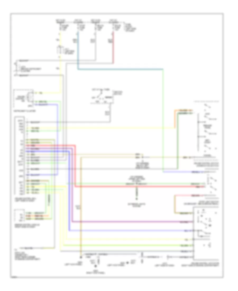
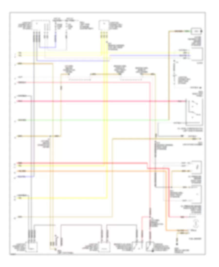
AIR CONDITIONING
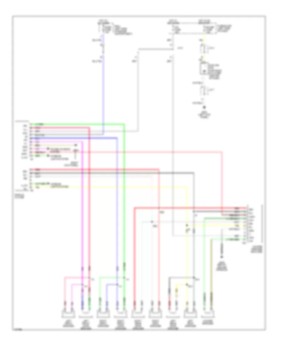
A/C Wiring Diagram (1 of 2) for Toyota Land Cruiser 1995
 https://portal-diagnostov.com/license.html
Automotive Electricians Portal FZCO
Automotive Electricians Portal FZCO
https://portal-diagnostov.com/license.html
https://portal-diagnostov.com/license.html
Automotive Electricians Portal FZCO
Automotive Electricians Portal FZCO
List of elements for A/C Wiring Diagram (1 of 2) for Toyota Land Cruiser 1995:
- (right side of i/p)
- 1994 vftc c
- A/c
- A/c amplifier (right side of i/p)
- A/c blower motor (right side of i/p)
- A/c cut relay (right side of i/p)
- A/c dual pressure switch (right front fender)
- A/c fuse 10a
- A/c magnetic clutch (right front of engine)
- A/c system amplifier (center of i/p)
- A/c thermistor (right side of i/p)
- Air inlet control servo motor (right side of i/p)
- Blower resistor (right side of i/p)
- Blower speed control relay (right side of i/p)
- Engine control module (right side of i/p)
- Fuse block (left side of i/p)
- G131 (air intake chamber)
- G200 (left kick panel)
- G203 (right kick panel)
- Gauge fuse 10a
- Heater blower motor (right side of i/p)
- Heater fusible link 30a
- Heater relay
- Hot at all times
- Hot in run or start
- Ignition switch (st2)
- J/c 2 (left side of i/p)
- J/c 4 (left side of i/p)
- J/c 6
- J/c 7 (right side of i/p)
- J/c 8 (right side of i/p)
- R/b 1 (left kick panel)
- Red
- Water temperature switch (left side of engine)
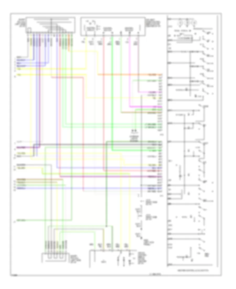
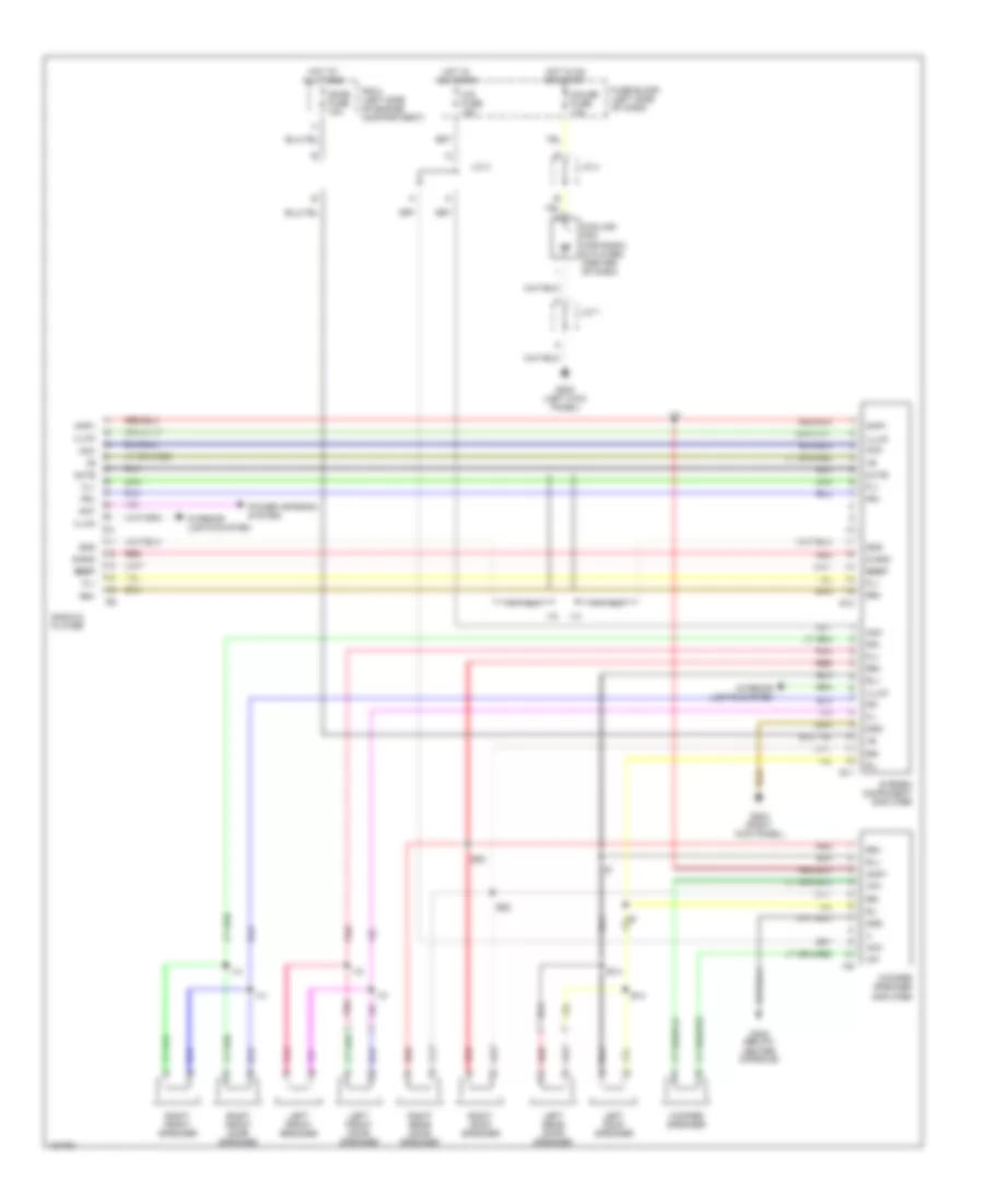
A/C Wiring Diagram (2 of 2) for Toyota Land Cruiser 1995
List of elements for A/C Wiring Diagram (2 of 2) for Toyota Land Cruiser 1995:
- 1994 vftc c
- A/c
- A10
- A11
- A12
- A13
- A14
- A15
- A16
- A17
- A18
- A19
- A20
- Air mix control servo motor (center of i/p)
- Air vent mode control servo motor (center of i/p)
- B/l
- B10
- B11
- B12
- B13
- B14
- B15
- B16
- B17
- B18
- Control circuit
- Control switch
- Def
- F/d
- Face
- Foot
- G200 (left kick panel)
- H10
- H11
- Heater control & a/c switch
- Interior lights system
- J/c 5 (right side of i/p)
- Off
- Rec/ frs
- Short pin (a/c) (left side of i/p)
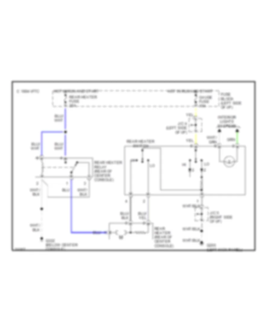
Rear Heater Wiring Diagram for Toyota Land Cruiser 1995
List of elements for Rear Heater Wiring Diagram for Toyota Land Cruiser 1995:
- 1994 vftc c
- Fuse block (left side of i/p)
- G200 (left kick panel)
- G302 (below center console)
- Gauge fuse 10a
- Hot in run and start
- Interior lights systems
- J/c 4 (left side of i/p)
- J/c 5 (right side of i/p)
- Rear heater (rear of center console)
- Rear heater fuse 20a
- Rear heater relay (rear of center console)
- Rear heater switch
ANTI-LOCK BRAKES
Anti-lock Brake Wiring Diagrams for Toyota Land Cruiser 1995
List of elements for Anti-lock Brake Wiring Diagrams for Toyota Land Cruiser 1995:
- (cowl harn, behind cluster) i7
- (cowl harn, left kick panel)
- (cowl harness, behind cluster)
- (floor harn, behind left side of rear bumper)
- (frame harn, left rear wheelhouse)
- A10
- A11
- A12
- A13
- A14
- A15
- A16
- A20
- A21
- A5/1
- A5/3
- A5/4
- A6/1
- A6/2
- A6/3
- A6/4
- A6/5
- A7/1
- A7/2
- A7/3
- A7/4
- A8/1
- A8/2
- A8/4
- A8/5
- A8/6
- Abs actuator (left side of engine compartment)
- Abs deceleration sensor (under right front seat)
- Abs ecu (left side of i/p)
- Abs fuse 60a
- Abs relay (left side of engine compartment)
- Abs warning ind
- Ast
- B10
- B11
- B12
- B13
- B14
- B15
- B16
- B17
- B18
- B19
- B20
- B21
- B22
- B23
- B24
- B25
- B26
- B28
- Bat
- Brake fluid level switch (brake fluid reservoir)
- Combination meter
- Data link connector 1 (right rear corner of engine compartment)
- Diff lock ind
- Diff lock indicator switch
- E23
- Ecu-b fuse 10a
- Ecu-ig fuse 15a
- Exi
- Fl+
- Fl-
- Fr+
- Fr-
- Fss
- Fuse block (left side of i/p)
- G200 (left kick panel)
- G203 (right kick panel)
- G206 (under center console)
- Gauge fuse 10a
- Gnd
- Gs1
- Gs2
- Gst
- Hot at all times
- Hot in run
- Ig1
- J/c 1 (left side of i/p)
- J/c 6 (behind left side of i/p)
- Left front abs speed sensor
- Left rear abs speed sensor
- Nca
- Parking brake switch (under front center of passenger compartment)
- Pkb
- Pnk
- R/b #2 (left side of engine compartment)
- Red
- Right front abs speed sensor
- Right rear abs speed sensor
- Rl+
- Rl-
- Rr+
- Rr-
- Rss
- Sfl
- Sfr
- Srr
- Stop fuse 10a
- Stop light switch (left side of i/p)
- Stp
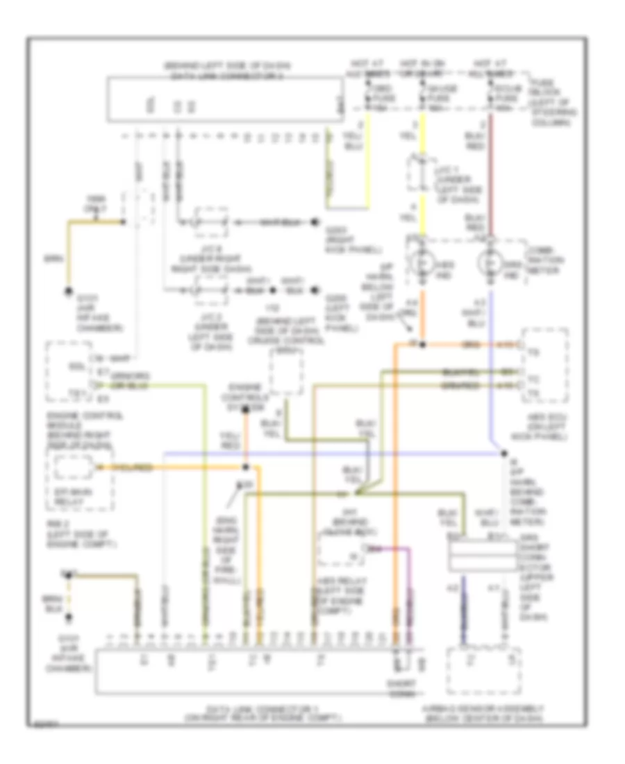
COMPUTER DATA LINES
Computer Data Lines for Toyota Land Cruiser 1995
List of elements for Computer Data Lines for Toyota Land Cruiser 1995:
- (behind left side of dash) cruise control ecu
- (behind left side of dash) data link connector 3
- (eng harn, right side of fire- wall)
- (i/p harn, below left side of dash)
- A13
- A15
- Abs ecu (on left kick panel)
- Abs ind
- Abs relay (left side of engine compt)
- Airbag sensor assembly (below center of dash)
- Bat
- Comb- ination meter
- Data link connector 1 (on right rear of engine compt)
- E17
- E20
- Ecu-b fuse 10a
- Efi main relay
- Engine control module (behind right side of dash)
- Engine controls system
- Fuse block (left of steering column)
- G131 (air intake chamber)
- G200 (left kick panel)
- G203 (right kick panel)
- Gauge fuse 10a
- Hot at all times
- Hot in on or start
- I12
- I6 (i/p harn, behind comb- ination meter)
- Ih1 (behind glove box)
- J/c 1 (under left side of dash)
- J/c 2 (under left side of dash)
- J/c 8 (under right right side dash)
- Obd fuse 15a
- Only
- R/b 2 (left side of engine compt)
- Sdl
- Short conn
- Srs ind
- Srs short conn- ector (upper left side of dash)
- Te1
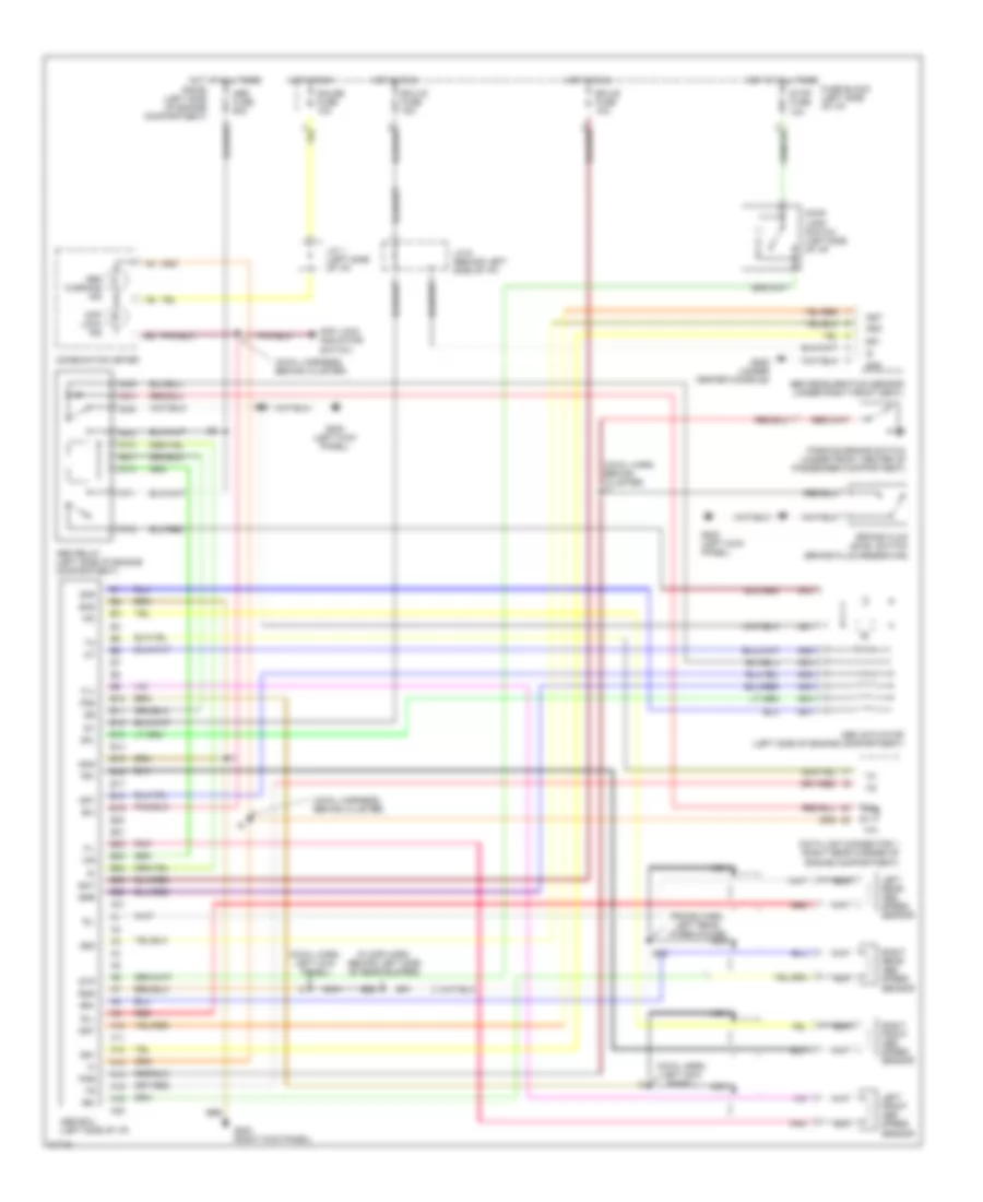
CRUISE CONTROL
Cruise Control Wiring Diagram for Toyota Land Cruiser 1995
List of elements for Cruise Control Wiring Diagram for Toyota Land Cruiser 1995:
- (1996)
- 11 e5
- 18 e7
- 9 e4
- Acc
- Batt
- Cancel
- Ccs
- Cms
- Cruise control actuator (right side of engine compartment)
- Cruise control ecu (left side of dash)
- Cruise control ind
- Cruise control switch (combination switch)
- Data link connector 1 (right rear corner of engine compartment)
- Ect
- Ecu-b fuse 10a
- Ecu-ig fuse 15a
- Engine control module (right side of dash)
- Exterior lights system
- Fuse block (left side of dash)
- G200 (left kick panel)
- G203 (right kick panel)
- Gauge fuse 10a
- Gnd
- Hot at all times
- Hot in on and acc
- I12
- I5 (i/p harness, below left side of dash)
- Idl
- Ignition switch
- Instrument cluster
- J/c 1 (left end of dash)
- J/c 2 (left side of dash)
- J/c 6 (behind instrument cluster)
- Main
- N&c
- Od1
- Off
- Pkb
- Red
- Resume/ accel
- Set/ coast
- Spd
- Start
- Stop fuse 10a
- Stop light switch (on bracket, above brake pedal)
- Stp+
- Stp-
- Vr1
- Vr2
- Vr3
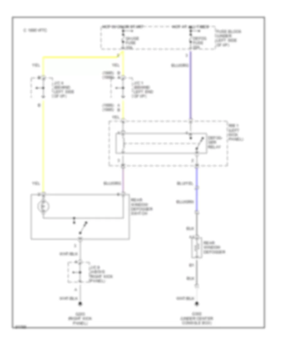
DEFOGGERS
Defogger Wiring Diagram for Toyota Land Cruiser 1995
List of elements for Defogger Wiring Diagram for Toyota Land Cruiser 1995:
- (1995) (1996)
- (1996) (1995)
- A b
- B a
- C 1995 vftc
- Defog fuse 20a
- Defog- ger relay
- Fuse block (under left side of i/p)
- G203 (right kick panel)
- G302 (under center console box)
- Gauge fuse 10a
- Hot at all times
- Hot in on or start
- J/c 1 (behind left end of i/p)
- J/c 4 (behind left side of i/p)
- J/c 8 (above right kick panel)
- R/b 1 (left kick panel)
- Rear window defogger
- Rear window defogger switch
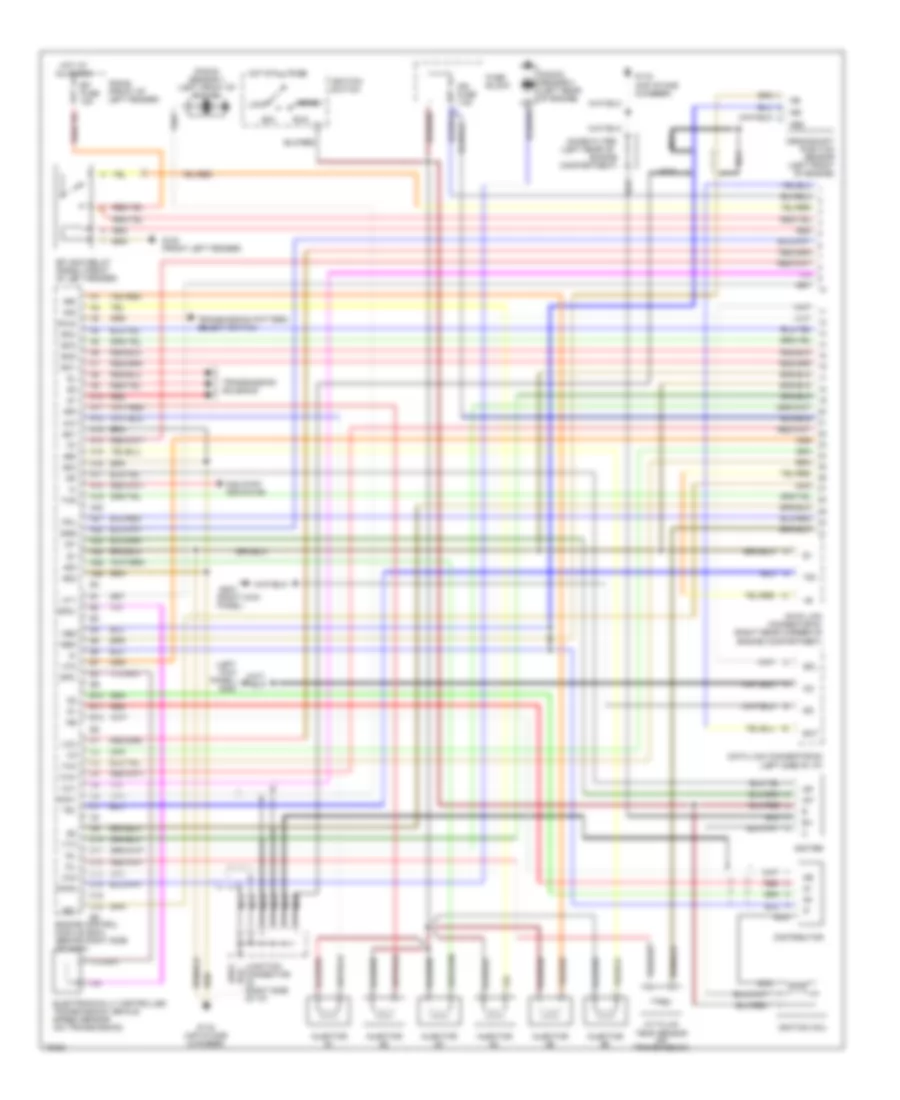
ENGINE PERFORMANCE
4.5L
4.5L, Engine Performance Wiring Diagrams (1 of 2) for Toyota Land Cruiser 1995
List of elements for 4.5L, Engine Performance Wiring Diagrams (1 of 2) for Toyota Land Cruiser 1995:
- #10
- #20
- #30
- #40
- #50
- #60
- (air intake chamber)
- (left kick panel) g200
- (left rear of
- (left side of i/p)
- (right kick panel)
- 2nd strt indicator
- A/t fluid temp sensor (on transmission)
- A10
- A11
- A12
- A13
- A14
- A15
- A16
- A17
- A18
- A19
- A20
- A21
- A22
- A23
- A24
- A25
- A26
- Acc
- B10
- B11
- B12
- Bat
- C10
- C11
- C12
- C13
- C14
- C15
- C16
- Compartment)
- Crankshaft position sensor (left front of engine)
- Data link connector #1 (right rear corner of engine compartment)
- Data link connector #3
- Distributor
- E01
- E02
- E03
- E21
- Efi fuse 15a
- Efi main relay (r/b #2) (front of left fender)
- Egr
- Electronically controlled transmission vehicle speed sensor (on transmission)
- Engine
- Engine control module (ecm) (behind right side of dash)
- Fpu
- Fuse block
- G100 (front left fender)
- G116
- G116 (air intake chamber)
- G203
- Hold
- Hot at all times
- Ht1
- Ht2
- Idl
- Igf
- Ign fuse 7.5a
- Igniter
- Ignition coil
- Ignition switch
- Igt
- Injector #1
- Injector #2
- Injector #3
- Injector #4
- Injector #5
- Injector #6
- Isc1
- Isc2
- Isc3
- Isc4
- Junction connector j9 (right side of i/p)
- Knk1
- Knk2
- Knock sensor 1 (left front of engine)
- Knock sensor 2 (left rear of engine)
- Lock
- Nca
- Ne-
- Ne2
- Ne2+
- Ne2-
- Noise filter
- Oil
- Ox1
- Ox2
- R/b #2 (front of left fender)
- Red
- Run
- Sdl
- Sp2+
- Sp2-
- Start
- Te1
- Tha
- Thg
- Thw
- Transmission pattern select switch
- Transmission solenoid
- Vcc
- Vta
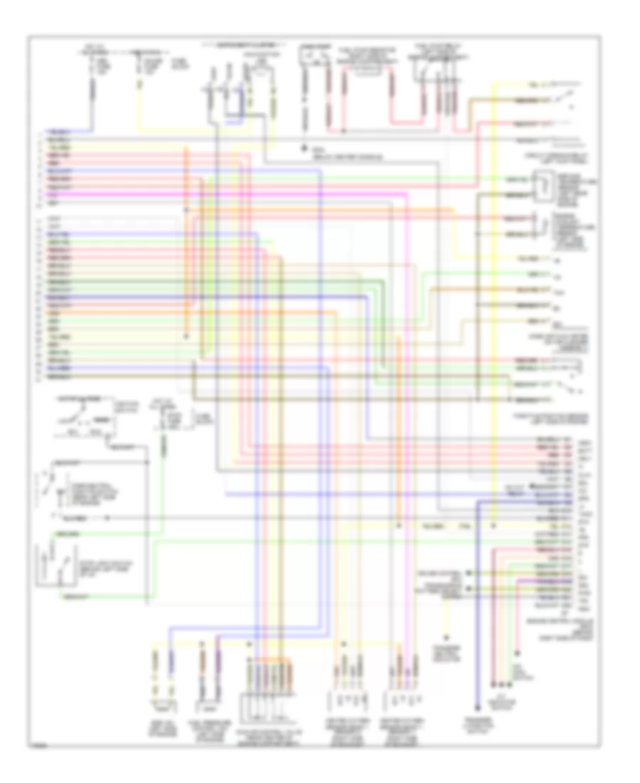
4.5L, Engine Performance Wiring Diagrams (2 of 2) for Toyota Land Cruiser 1995
List of elements for 4.5L, Engine Performance Wiring Diagrams (2 of 2) for Toyota Land Cruiser 1995:
- (below center console)
- A/c
- A/c cut
- A/t indicator switch
- Acc
- Batt
- Circuit opening relay (left kick panel)
- Cruise control ecu
- D10
- D11
- D12
- D13
- D14
- D15
- D16
- D17
- D18
- D19
- D20
- D21
- D22
- Dd1
- Dd2
- E21
- Egr gas temperature sensor (left rear side of engine)
- Egr vsv (left side of engine)
- Engine control module (ecm) (behind right side of dash)
- Engine coolant temperature sensor (left side of engine)
- Fpr
- Fuel pressure control vsv (left side of engine)
- Fuel pump
- Fuel pump relay (left side of engine compartment)
- Fuel pump resistor (right side of engine compartment)
- Fuse block
- G302
- Gauge fuse 10a
- Heated oxygen sensor (bank 1, sensor 1) (right side of exhaust)
- Heated oxygen sensor (bank 1, sensor 2) (right side of exhaust)
- Hot at all times
- Hot in run
- Ht1
- Ht2
- Idle air control valve (rear center of engine compartment)
- Ignition switch
- Igsw
- Instrument cluster
- Lock
- Malfunction ind
- Mass air flow meter (on air cleaner assembly)
- Mrly
- Nsw
- O/d main switch
- Obd fuse 15a
- Oilw
- Ox1
- Ox2
- P/n
- Park/neutral position switch (rear left side of engine)
- Pwr
- Red
- Relay
- Run
- Sdl
- Spd
- Speed
- Sta
- Start
- Stop fuse 10a
- Stop light switch (behind left side of i/p)
- Stp
- Tacho
- Taco
- Tfn
- Tha
- Throttle position sensor (left side of engine)
- Transfer l4 position switch
- Transfer neutral indicator
- Transmission pattern select switch
EXTERIOR LIGHTS
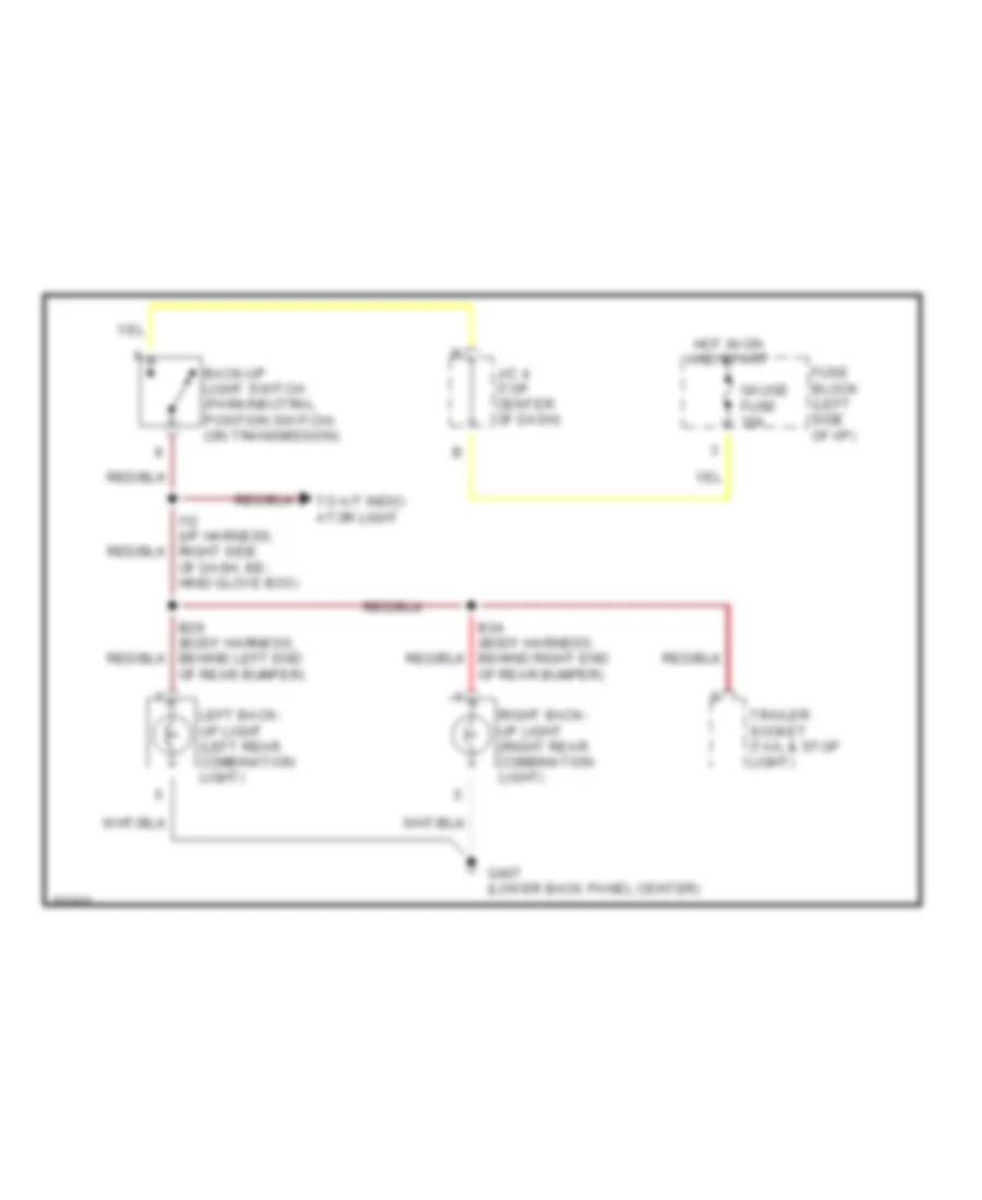
Back-up Lamps Wiring Diagram for Toyota Land Cruiser 1995
List of elements for Back-up Lamps Wiring Diagram for Toyota Land Cruiser 1995:
- B29 (body harness, behind left end of rear bumper)
- B34 (body harness, behind right end of rear bumper)
- Back-up light switch (park/neutral position switch) (on transmission)
- Fuse block (left side of i/p)
- G407 (lower back panel center)
- Gauge fuse 10a
- Hot in on and start
- I12 (i/p harness, right side of dash, be- hind glove box)
- J/c 4 (top center of dash)
- Left back- up light (left rear combination light)
- Right back- up light (right rear combination light)
- To a/t indic- ator light
- Trailer socket (tail & stop light)
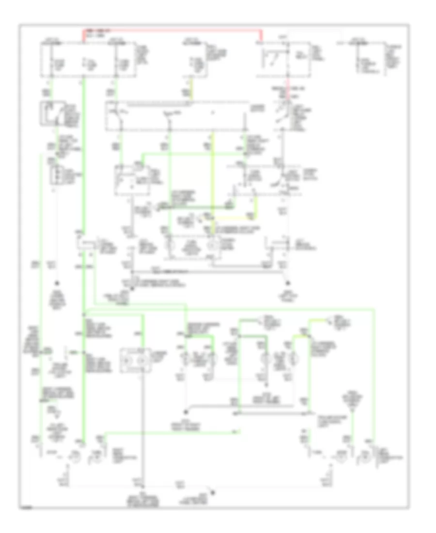
Exterior Lamps Wiring Diagram for Toyota Land Cruiser 1995
List of elements for Exterior Lamps Wiring Diagram for Toyota Land Cruiser 1995:
- (1995)
- (1996, 97)
- (body har- ness, behind center of rear bumper) b33
- (body harness, behind left end of rear bumper) b30
- (i/p har-
- (i/p harness, right side of steering column) i7
- (or) red (1997)
- B31 (body harness, behind left side of rear bumper)
- B34 (body har- ness, behind right end of rear bumper)
- Combin- ation meter
- Combin- ation switch
- Flash relay
- From splice b30 (diagram 1 of 1)
- From splice i7 (diagram 1 of 1)
- Fuse block (left side of i/p)
- Fusible link box (front of bat- tery)
- G100 (front of left front fender)
- G101 (front of right front fender)
- G200 (left kick panel)
- G203 (1996, 97 only) (right kick panel)
- G302 (under center console box)
- G407 (lower back panel center)
- Haz- horn fuse 15a
- Hazard switch
- Head
- High mounted stop light
- Hot at all times
- I1 (i/p har- ness, upper left end of dash)
- I12 (i/p harness, right side of dash, behind glove box)
- I7 (i/p harness, right side of steering column)
- J/c 1 (upper left end of dash)
- J/c 2 (behind left side of dash)
- J/c 7 (behind glove box)
- Left rear combination light
- Lh rh front turn signal lights
- License plate light
- Light control switch
- Light retainer relay (upper left kick panel)
- Ness, right side of steering column) i7
- Off
- R/b 1 (left kick panel)
- R/b 2 (left kick panel)
- R/b 2 (left side of engine compt)
- Red
- Rh lh front parking lights
- Right rear combination light
- Stop
- Stop fuse 10a
- Stop light switch (above brake pedal)
- Tail
- Tail fuse 15a
- Tail relay
- To left rear comb light (diagram 1 of 1)
- To splice i1 (diagram 1 of 1)
- To splice i7 (diagram 1 of 1)
- Trailer socket (tail & stop light)
- Trailer socket (turn signal light)
- Turn
- Turn fuse 7.5a
- Turn signal indicator lights
- Turn signal switch
GROUND DISTRIBUTION
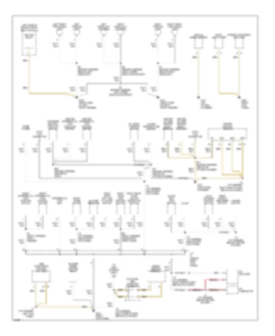
Ground Distribution Wiring Diagram (1 of 3) for Toyota Land Cruiser 1995
List of elements for Ground Distribution Wiring Diagram (1 of 3) for Toyota Land Cruiser 1995:
- (left side of engine compt) relay block 2
- (s 4a,s 5b) srs shorting connector
- A/c amplifier
- A/c thermistor
- Abs electronic control unit (ecu)
- Airbag sensor assembly
- Auto antenna control switch
- B1 (body harness, right fender)
- B6 (body harness, inside right front door)
- Blower resistor
- Blower speed control relay
- Center differential lock control motor
- Center differential lock indicator switch
- Clock
- Data link connector
- Differential lock ecu
- E1 (engine harness, behind right headlight)
- E17 (engine harness, above air intake chamber)
- E22 (engine harness, center of dash)
- E3 (engine harness, right upper radiator support)
- E4 (engine harness, left upper radiator support)
- E5 (engine harness, behind left headlight)
- Efi main relay
- Engine control module
- Eo1
- Eo2
- Eo3
- Front differential lock control motor
- Front differential lock position switch
- Front wiper motor
- G100 (front side of left front fender)
- G101 (front side of right front fender)
- G131 (air intake chamber)
- G203 (right kick panel)
- Glove box light switch
- Hazard switch
- Heated oxygen sensor bank 1 sensor 1
- Heated oxygen sensor bank 1 sensor 2
- I12 (i/p harness, right side of dash, behind glove box)
- I13 (i/p harness, right side of dash, behind glove box)
- I14 (i/p harness, above right kick panel)
- I15 (i/p harness, above right kick panel)
- I16 (i/p harness, behind center of dash)
- I17 (i/p harness, behind center of dash)
- I18 (i/p harness, right side of dash, below glove box)
- I3 (i/p harness, left kick panel)
- J/c (above right kick panel)
- Left front turn signal light
- Left headlight low beam
- Left parking light
- Noise filter
- Oil level warning switch
- Radio and player
- Rear window defogger switch
- Right door key lock & unlock switch
- Right door lock control switch
- Right front door unlock detection switch
- Right front turn signal light
- Right headlight low beam
- Right parking light
- Stereo component amplifier
- To g200 (diagram 2 of 3)
- Transfer neutral position switch
- Vehicle speed sensor
- Water temperature switch
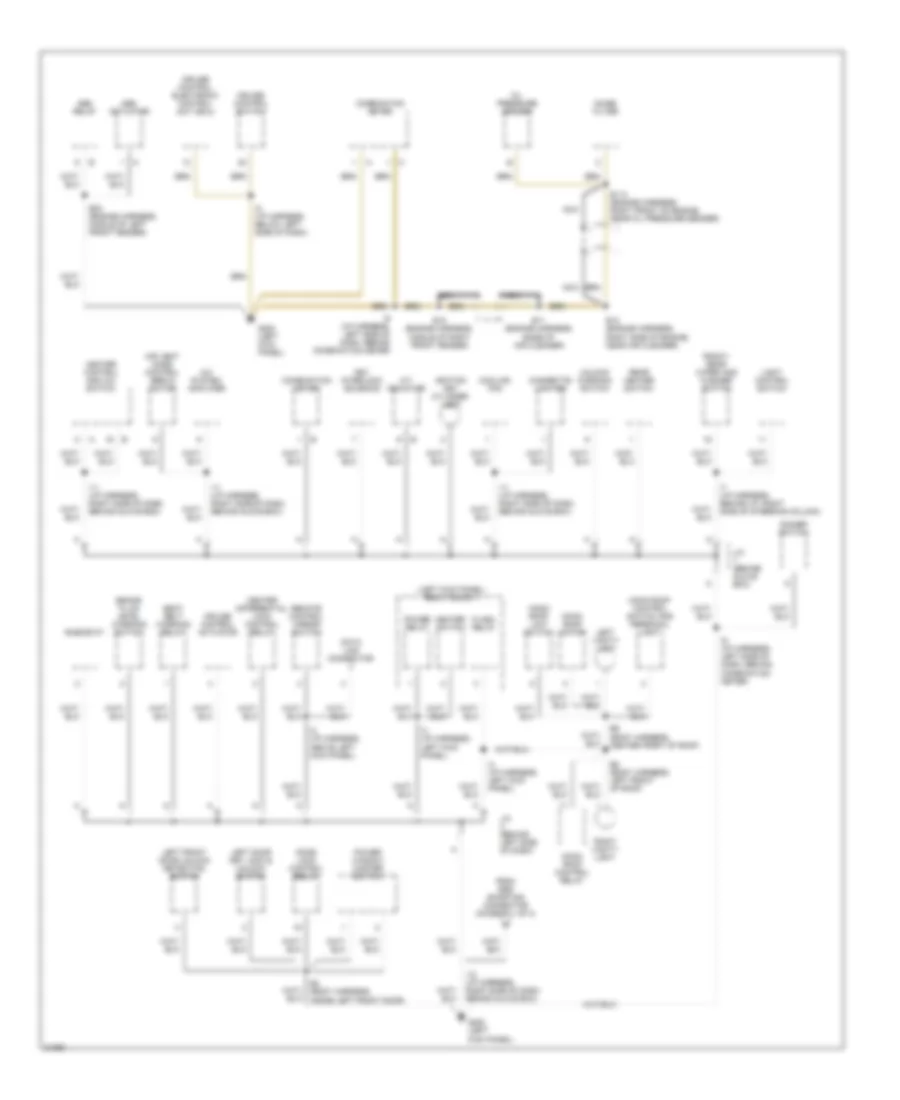
Ground Distribution Wiring Diagram (2 of 3) for Toyota Land Cruiser 1995
List of elements for Ground Distribution Wiring Diagram (2 of 3) for Toyota Land Cruiser 1995:
- (left kick panel) relay block 1
- A/c system amplifier
- A/t indicator
- Abs actuator
- Abs relay
- Air vent mode control servo motor
- B2 (body harness, inside left front door)
- B8 (body harness, left front of roof)
- B9 (body harness, center front of roof)
- Brake fluid level warning switch
- Center differential lock control relay
- Cigarette lighter
- Combination meter
- Cooling fan
- Cruise control actuator
- Cruise control electronic control unit (ecu)
- Cruise control switch
- Data link connector
- Dimmer switch
- Door lock control relay
- E10 (engine harness, middle of right front fender)
- E11 (engine harness, base of air cleaner)
- E113 (engine harness, right front of engine, near oil pressure sender)
- E12 (engine harness, right side of engine, near air cleaner)
- E23 (engine harness, middle of left front fender)
- Flash relay
- From srs shorting connector (diagram 1 of 3)
- Front/ rear wiper and washer switch
- G200 (left kick panel)
- Heater control and a/c switch
- Heater switch
- I11 (i/p harness, right side of dash, behind glove box)
- I12 (i/p harness, right side of dash, behind glove box)
- I2 (i/p harness, above left kick panel)
- I3 (i/p harness, left kick panel)
- I5 (i/p harness, below left side of dash)
- I6 (i/p harness, left side of dash, behind combination meter)
- I7 (i/p harness, behind i/p, right side of steering column)
- Ignition key cylinder light
- J/c (behind glove box)
- J/c (behind left side of dash)
- Key interlock solenoid
- Left door key lock & unlock switch
- Left front door unlock detection switch
- Left vanity light
- Light control switch
- Moon roof control relay
- Moon roof control switch and personal light
- Moon roof limit switch
- Moon roof motor
- Nca
- Noise filter
- Oil pressure sender
- Power relay
- Power window master switch
- Rear heater switch
- Remote control mirror switch
- Rheostat
- Right vanity light
- Seat belt warning relay
- Unlock warning switch
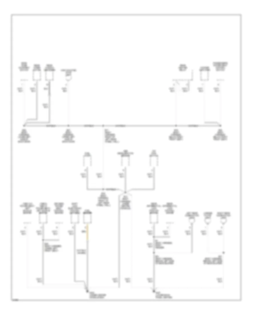
Ground Distribution Wiring Diagram (3 of 3) for Toyota Land Cruiser 1995
List of elements for Ground Distribution Wiring Diagram (3 of 3) for Toyota Land Cruiser 1995:
- (1995 w/o power seat) left buckle switch
- (1996 & 1995 w/ power seat) left buckle switch
- Abs deceleration sensor
- B1 (body harness, right fender)
- B13 (body harness, under center console)
- B16 (body harness, front of left rear wheel well)
- B17 (body harness, front of left rear wheel well)
- B19 (body harness, below right front seat)
- B20 (body harness, below right front seat)
- B27 (body harness, upper left side of back door)
- B28 (body harness, lower left side of back door)
- B31 (body harness, behind left side of rear bumper)
- B35 (body harness, under left front seat)
- Back door courtesy switch
- Driver's power seat control switch
- Fuel pump
- Fuel sender
- G302 (under center console box)
- G407 (lower back panel center)
- High mounted stop light
- Left rear combination light
- License plate light
- O/d main switch
- Passenger's power seat control switch
- Rear differential lock control motor
- Rear differential lock postion switch
- Rear heater relay
- Rear window defogger
- Rear wiper motor
- Right rear combination light
- Shift lock electronic control unit (ecu)
- Woofer amplifier
HEADLIGHTS
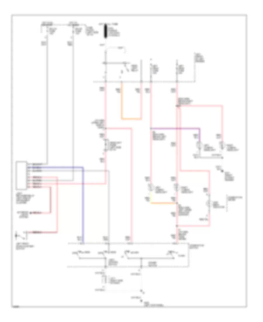
Headlight Wiring Diagram for Toyota Land Cruiser 1995
List of elements for Headlight Wiring Diagram for Toyota Land Cruiser 1995:
- (eng harn, behind right headlight) e2
- (i/p harn upper left side of dash) i1
- Combination meter
- Combination switch
- Dimmer switch
- E4 (eng harn, left upper radiator support)
- E5 (eng harn, behind left headlight)
- Ecu-b fuse 10a
- Ecu-ig fuse 15a
- Exterior lights system
- Flash
- Fuse block (left side of i/p)
- G101 (front of right fender)
- G200 (left kick panel)
- Head
- Head- light relay
- Headlight diode (left side of i/p)
- High
- High beam indicator
- Hot at all times
- Hot in on or start
- I6 (i/p harn, behind comb meter)
- J/b 2 (front of left fender)
- J/c 7 (right side of dash)
- Left front door courtesy switch
- Left head fuse 15a
- Left hi beam headlight
- Left lo beam headlight
- Light control switch
- Light retainer relay (left side of instrument cluster)
- Off
- Right hi beam headlight
- Right lo beam headlight
- Tail
HORN
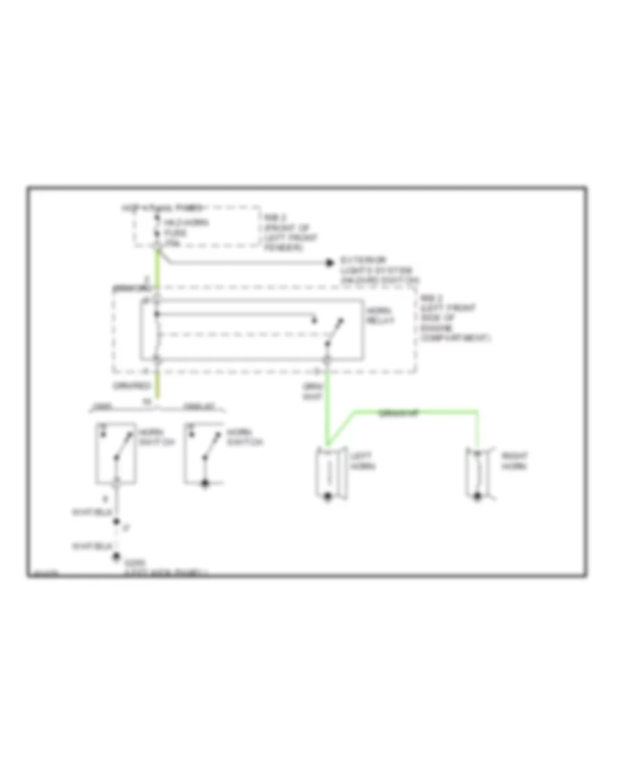
Horn Wiring Diagram for Toyota Land Cruiser 1995
List of elements for Horn Wiring Diagram for Toyota Land Cruiser 1995:
- 1996-97
- Exterior lights system (hazard switch)
- G200 (left kick panel)
- Haz-horn fuse 15a
- Horn switch
- Horn relay
- Hot at all times
- Left horn
- R/b 2 (front of left front fender)
- R/b 2 (left front side of engine compartment)
- Right horn
INSTRUMENT CLUSTER
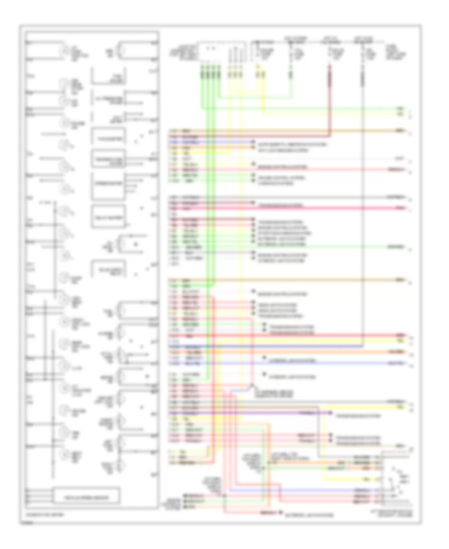
Instrument Cluster Wiring Diagram (1 of 2) for Toyota Land Cruiser 1995
List of elements for Instrument Cluster Wiring Diagram (1 of 2) for Toyota Land Cruiser 1995:
- (i/p harn, top right side of dash) i12
- 2nd gear start ind
- A/t indicator illum
- A/t indicator switch (on shift linkage)
- A/t oil temp ind
- A/t park position ind
- A10
- Abs ind
- Anti-lock brakes system
- B b
- B10
- B11
- B12
- B13
- Brake ind
- Bulb check relay
- C10
- C11
- C12
- C13
- C14
- C15
- C16
- Center diff lock ind
- Charge ind
- Check engine ind
- Combination meter
- Cruise control system
- Cruise ind
- D10
- D11
- D12
- D13
- Delay buffer
- Door ind
- Ecu-b fuse 10a
- Engine controls system
- Exterior lights system
- Front diff lock ind
- Fuel gauge
- Fuel ind
- Fuse block (left side of dash)
- Gauge fuse 10a
- Headlights system
- High beam ind
- Hot at all times
- Hot in on or start
- Hot in park or head
- Hot in run
- I6 (i/p harness, behind combination meter)
- Ign fuse 7.5a
- Illum
- Interior lights system
- Junction connector 1 (top left end of dash)
- Left turn ind
- O/d ind
- Oil level ind
- Oil pressure gauge
- Pnk
- Power ind
- Rear diff lock ind
- Red
- Right turn ind
- Seat belt ind
- Speedometer
- Srs ind
- Starting/charging system
- Tachometer
- Tail fuse 15a
- Temperature gauge
- Transmissions system
- Vehicle speed sensor
- Volt meter
- Warning systems
Instrument Cluster Wiring Diagram (2 of 2) for Toyota Land Cruiser 1995
List of elements for Instrument Cluster Wiring Diagram (2 of 2) for Toyota Land Cruiser 1995:
- (engine harn, base of air cleaner) e11
- (engine harn, middle of right front fender) e10
- (i/p harn, behind combination meter) i6
- Brake fluid level warning switch (brake master cylinder)
- Cig fuse 15a
- Clock
- Dome fuse 10a
- E12 (engine harness, right side of engine)
- E13 (engine harn, right front of engine)
- E17
- E18 (engine harness, (top left rear of engine)
- Fuel sender
- G131 (air intake chamber)
- G200 (left kick panel)
- G203 (right kick panel)
- G302 (below center console)
- Hot at all times
- I14
- I6 (i/p harn, behind combination meter)
- Junction connector 2 (upper left end of dash)
- Junction connector 3 (top left end of dash)
- Junction connector 4 (top center of dash)
- Junction connector 7 (right side of dash)
- Junction connector 8 (right end of dash)
- Nca (shielded)
- Oil level warning switch (left side of engine)
- Oil pressure sender (right side of engine)
- Oil pressure sender radio noise filter (right side of engine)
- Parking brake switch (parking brake handle assy)
- Pnk
- R/b 2 (left side of engine compartment)
- Red
- Water temperature sender (left side of engine)
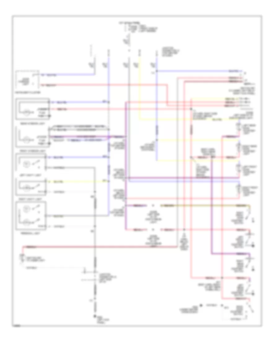
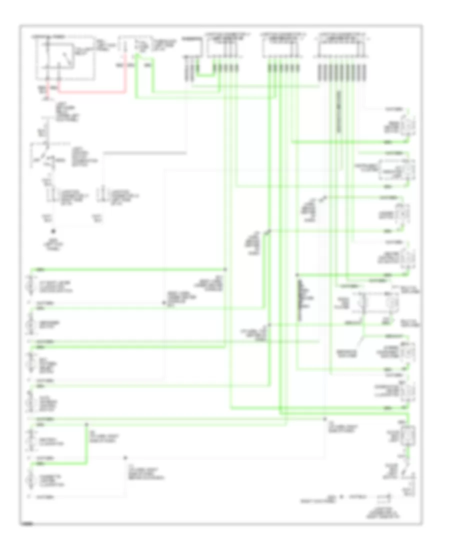
INTERIOR LIGHTS
Courtesy Lamp Wiring Diagram for Toyota Land Cruiser 1995
List of elements for Courtesy Lamp Wiring Diagram for Toyota Land Cruiser 1995:
- (body harn, right rear door sill) b23
- (i/p harn, below left side of dash) i5
- (w/ moon roof)
- (w/o moon roof)
- B10
- B11
- B13
- B17 (body harn, front of left rear wheelwell)
- Back door courtesy switch
- Dcty
- Diode (left side of i/p) (for interior light)
- Dome fuse 10a
- Door
- Door warning light
- Front interior light
- G200 (left kick panel)
- G302 (under center console box)
- Hot at all times
- I11 (i/p harn, right side of dash, behind glove box)
- I12
- I14
- I14 (i/p harn, above right kick panel)
- I5 (i/p harn, below left side of dash)
- I9 (i/p harn, top center of dash)
- Ignition key cylinder light
- Ignition key cylinder light relay (right kick panel)
- Instrument cluster
- Junction connector j2 (left side of i/p)
- Junction connector j3 (top center of dash)
- Left front door courtesy light
- Left front door courtesy switch
- Left rear door courtesy light
- Left rear door courtesy switch
- Left vanity light
- Off
- Personal light
- R/b 2 (front side of left fender)
- Rear interior light
- Right front door courtesy light
- Right front door courtesy switch
- Right rear door courtesy light
- Right rear door courtesy switch
- Right vanity light
Instrument Illumination Wiring Diagram for Toyota Land Cruiser 1995
List of elements for Instrument Illumination Wiring Diagram for Toyota Land Cruiser 1995:
- (body harn, under center console) b13
- (i/p harn, behind center of dash)
- (separate amplifier)
- A/t indicator lamp
- A/t shift lever illumination (o/d main switch)
- Ashtray illumination
- Auto antenna control switch
- B12
- B13 (body harn, under center console)
- Built-in amplifier
- Cigarette lighter illumination
- Combination meter illumination
- Defogger switch
- Ect pattern select switch
- Fuse block (left side of i/p)
- G200 (left kick panel)
- G203 (right kick panel)
- Glove box light
- Glove box light switch
- Hazard switch
- Head
- Heater control & a/c switch
- Hot at all times
- I10 (i/p harn, right side of dash)
- I11 (i/p harn, right side of dash, behind glove box)
- I16
- I20 (i/p harn, right side of dash)
- I9 (i/p harn, top center of dash)
- Instrument cluster
- Junction connector j1 (left side of i/p)
- Junction connector j2 (left side of i/p)
- Junction connector j4 (center of i/p)
- Junction connector j5 (center of i/p)
- Junction connector j7 (right side of i/p)
- Junction connector j8 (right side of i/p)
- Light control switch (combination switch)
- Light retainer relay (upper left kick panel)
- Off
- R/b 1 (left kick panel)
- Radio and player
- Rear heater switch
- Red
- Rheostat
- Separate amplifier
- Stereo component amplifier
- Tail
- Tail fuse 15a
- Taillight relay
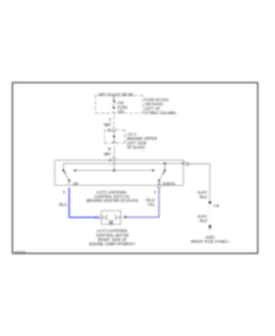
POWER ANTENNA
Power Antenna Wiring Diagram for Toyota Land Cruiser 1995
List of elements for Power Antenna Wiring Diagram for Toyota Land Cruiser 1995:
- Auto antenna control motor (right side of engine compartment)
- Auto antenna control switch (behind center of dash)
- Cig fuse 15a
- Down
- Fuse block (on dash, left of strng column)
- G203 (right kick panel)
- Hot in acc or on
- I16
- J/c 3 (behind upper left side of dash)
POWER DISTRIBUTION
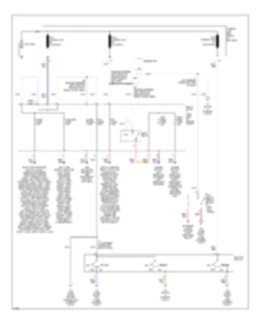
Power Distribution Wiring Diagram (1 of 2) for Toyota Land Cruiser 1995
List of elements for Power Distribution Wiring Diagram (1 of 2) for Toyota Land Cruiser 1995:
- (1995)
- (1996)
- (engine harness, left front of engine compt, right side of battery) e6
- Abs actuator, abs relay, abs electronic control unit (ecu)
- Abs fuse 60a
- Acc
- Am1 fuse 50a
- Am2 fusible link f7 (22 ga-pnk)
- Back door courtesy switch, clock, combination meter, open door warning light, interior light diode, left front door courtesy light, right front door courtesy light, left rear door courtesy light, right rear door courtesy light, left front door courtesy switch, right front door courtesy switch, left rear door courtesy switch, right rear door courtesy switch, front interior light, ignition key cylinder light, ignition key cylinder light relay, moon roof console switch and personal light, per- sonal light (w/o moon roof), radio and player, rear interior light, seat belt warning relay, stereo component amplifier, left vanity light, right vanity light
- Battery
- Circuit opening relay, data link connector 1, engine control module, fuel pump relay, fuel pump resistor, fuel sender and pump, heated oxygen sensor (bank 1 sensor 1), heated oxygen sensor (bank 1 sensor 2), idle air control valve, mass air flow meter, egr vacuum solenoid valve, fuel pressure control vacuum solenoid valve, efi main relay
- Coil
- Dimmer switch, left headlight low beam, left headlight high beam
- Dimmer switch, right headlight low beam, right headlight high beam, combination meter, high beam indicator light
- Dome fuse 10a
- E7 (engine harness, left front of engine compt, front of battery)
- E9 (engine harness, left front of engine compt, front of battery)
- Efi fuse 15a
- Exterior lights system (light retainer relay)
- Fusible link box (front of battery)
- Generator
- Haz-horn fuse 15a
- Head relay
- I1 (i/p harness, upper left end of dash)
- Ignition switch
- Left head fuse 15a
- Left turn signal indicator light, right turn signal indicator light, horn switch, left front turn signal light, right front turn signal light, left horn, right horn, hazard switch, left rear turn signal light, right rear turn signal light, trailer socket (turn signal light), horn relay, flasher relay
- Nca
- Off
- Red
- Relay block (left side of engine compt)
- Right head fuse 15a
- Start
- Tail relay (relay block 1: left kick panel)
- To fuse block (cig fuse) (diagram 2 of 2)
- To fuse block (ign fuse) (diagram 2 of 2)
- To fuse block (power fusible link) (diagram 2 of 2)
- To fuse block (tail fuse) (diagram 2 of 2)
- To splice i4 (diagram 2 of 2)
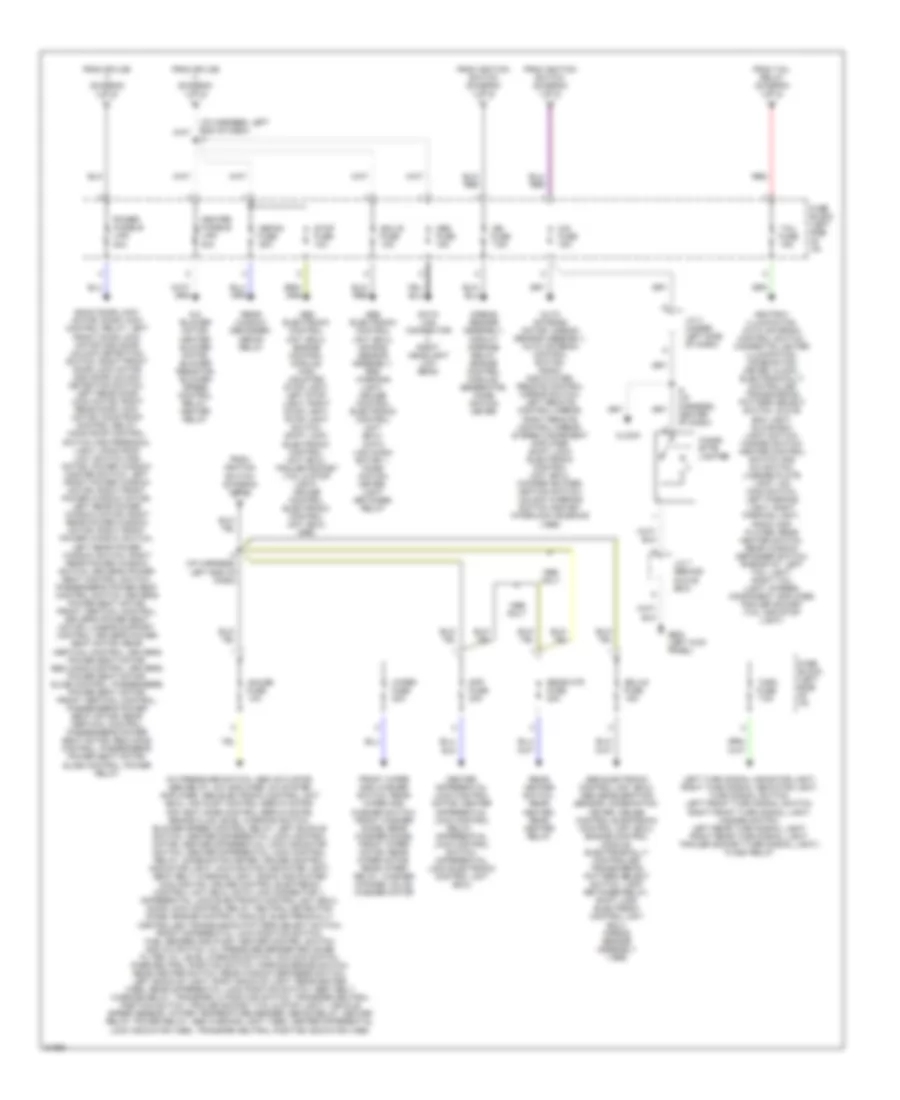
Power Distribution Wiring Diagram (2 of 2) for Toyota Land Cruiser 1995
List of elements for Power Distribution Wiring Diagram (2 of 2) for Toyota Land Cruiser 1995:
- (i/p harness, left end of dash) i4
- A/c blower motor, heater blower motor, blower resistor, blower speed control relay, heater relay
- A/c pressure switch, abs actuator, abs relay, a/c amplifier, a/c system amplifier, abs electronic control unit (ecu), air inlet control servo motor, air vent mode control servo motor, brake fluid level warning switch, blower speed control relay, left buckle switch, center differential lock control motor, center differential lock indicator switch, center differential lock control relay, combination meter, cruise control indicator light, malfunction indicator light, seat belt warning light, radio and player cooling fan, cruise control electronic control unit (ecu), data link connector 1, differential lock electronic control unit (ecu), door lock control relay, neutral detection diode, engine control module, electronically controlled transmission pattern select switch, front differential lock position switch, fuel sender and pump, heater control switch and a/c switch, oil pressure sender and noise filter, oil level warning switch, o/d main switch, park/neutral position switch, parking brake switch, rear heater switch, rear window defogger switch, left back-up light, right back-up light, rear heater (1995), rear differential lock position switch, seat belt warning relay, transfer l4 position switch, transfer neutral position switch, trailer socket (tail & stop light), vehicle speed sensor, water temperature sender, defog relay, heater relay, power relay, abs warning light (1995), center differential lock indicator (1995), transfer neutral position indicator (1995)
- Abs electronic control unit (ecu), abs deceleration sensor, combination meter, cruise control electronic control unit (ecu), engine control module, electronically controlled transmission pattern select switch, light retainer relay, shift lock electronic control unit (ecu), airbag sensor assembly (1995)
- Abs electronic control unit (ecu), air bag sensor assembly, srs warning light, cruise control electronic control unit (ecu), data link conn- ector 1, comb- ination meter, light retainer relay
- Abs electronic control unit (ecu), engine control module, high mounted stop light, left stop light, right stop light, stop light switch, shift lock electronic control unit (ecu), trailer socket (tail & stop light), cruise control electronic control unit (ecu) (i995)
- Airbag sensor assembly, circuit opening relay, engine control module, generator, comb- ination meter
- Ashtray illumination, auto antenna control switch, cigarette lighter illumination, combination meter, clock, electronically controlled transmission pattern select switch, glove box light, glove box light switch, hazard switch, heater control switch and a/c switch, license plate light, o/d main switch, left parking light, right parking light, radio and player, rear heater switch, rear window defogger switch, rheostat, left tail light, right tail light, stereo component amplifier, trailer socket (tail and stop light)
- Auto antenna motor, airbag sensor assembly, auto antenna control switch, radio and player, remote control mirror switch, left remote control mirror, right remote control mirror, stereo component amplifier, shift lock electronic control unit (ecu), woofer amlifier, ignition switch; unlock warning switch and key interlock solenoid (1995)
- Back door lock motor, door lock control relay, left front door lock motor and door unlock detection switch, right front door lock motor and door unlock detection switch, left rear door lock motor, right rear door lock motor, moon roof control relay, moon roof control switch and personal light, moon roof limit switch and motor, power window master switch, left front power window motor, right front power window motor, left rear power window motor, right rear power window motor, right front power window switch, left rear power window switch, right rear power window switch, driver's power seat control switch, passenger's power seat control switch, driver's power seat motor; front vertical control, driver's power seat motor; lumbar support control, driver's power seat motor; rear vertical control, driver's power seat motor; reclining control, driver's power seat motor; slide control, passenger's power seat motor; front vertical control, passenger's power seat motor; rear vertical control, passenger's power seat motor; reclining control, passenger's power seat motor; slide control, power relay
- Center differential lock control motor, center differential lock control relay, differential lock control switch, differential lock electronic control unit (ecu)
- Cig fuse 15a
- Cigar- ette lighter
- Clock
- Data link connector 3, right headlight low beam
- Defog fuse 20a
- Diff fuse 30a
- Ecu b fuse 10a
- Ecu-ig fuse 15a
- From ignition switch (diagram 1 of 2)
- From splice i1 (diagram 1 of 2)
- From tail relay (diagram 1 of 2)
- Front wiper and washer switch, rear wiper and washer switch, front washer diode, rear washer diode, front wiper motor, rear wiper motor, rear wiper relay, washer change valve, washer motor
- Fuse block (left side of i/p)
- G200 (left kick panel)
- Gauge fuse 10a
- Heater fusible link 40a
- I4 (i/p harness, left end of dash)
- I8 (i/p harness, center of dash)
- Ign fuse 7.5a
- J/c 3 (under left side of dash)
- J/c 7 (behind glove box)
- Left turn signal indicator light, right turn signal indicator light, turn signal switch, left front turn signal switch, right front turn signal light, hazard switch, left rear turn signal light, right rear turn signal light, trailer socket (turn signal light), flash relay
- Obd fuse 15a
- Only
- Power fusible link 30a
- Rear heater switch, rear heater, rear heater relay
- Rear window defogger, defog relay
- Rear-htr fuse 20a
- Red
- Stop fuse 10a
- Tail fuse 15a
- Turn fuse 7.5a
- Wiper fuse 20a
POWER DOOR LOCKS
Power Door Lock Wiring Diagram for Toyota Land Cruiser 1995
List of elements for Power Door Lock Wiring Diagram for Toyota Land Cruiser 1995:
- (body harn, in left front door) b4
- (body harn, in right front door) b7
- (body harn, left front door sill) b14
- (i/p harn, left kick panel) i3
- B14 (body harn, left front door sill)
- B5 (body harn, in left front door)
- Back door lock control motor
- Door lock control relay (right side of i/p)
- Door lock control switch (power window master switch)
- Fl power fuse 30a
- Fuse block (left side of i/p)
- G200 (left kick panel)
- G201 (right kick panel)
- Gauge fuse 10a
- Hot at all times
- Hot in run or start
- I14 (i/p harn, above right kick panel)
- I7 (i/p harn, right side of steering column)
- Interior lights system (door courtesy switches)
- Junction connector j2 (left side of i/p)
- Junction connector j7 (right side of i/p)
- Junction connector j8 (right side of i/p)
- Key off power window
- Left door key lock/unlock switch
- Left front door lock motor/door unlock detection switch
- Left rear door lock motor
- Lock
- Lock timer
- Power main relay
- Power window system (power window master switch)
- R/b #1 (left kick panel)
- Right door key lock/unlock switch
- Right door lock control switch
- Right front door lock motor/door unlock detection switch
- Right rear door lock motor
- Solid state
- Unlock
- Unlock timer
- Unlock warning switch (left side of i/p)
- Warning system (seat belt warning relay)
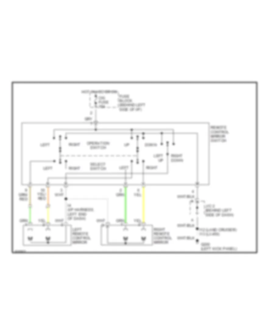
POWER MIRRORS
Power Mirror Wiring Diagram for Toyota Land Cruiser 1995
List of elements for Power Mirror Wiring Diagram for Toyota Land Cruiser 1995:
- Cig fuse 15a
- Down
- Fuse block (behind left side of i/p)
- G200 (left kick panel)
- Hot in acc or on
- I12 (land cruiser) i13 (lx450)
- J/c 2 (behind left side of dash)
- Left
- Left remote control mirror
- Left up
- Operation switch
- Remote control mirror switch
- Right
- Right down
- Right remote control mirror
- Select switch
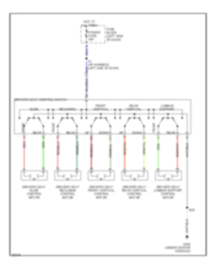
POWER SEATS
Driver Power Seat Wiring Diagram for Toyota Land Cruiser 1995
List of elements for Driver Power Seat Wiring Diagram for Toyota Land Cruiser 1995:
- B35
- Down
- Driver's seat control switch
- Driver's seat front vertical control motor
- Driver's seat lumbar support control motor
- Driver's seat rear vertical control motor
- Driver's seat reclining control motor
- Driver's seat slide control motor
- Front
- Front vertical
- Fuse block (left side of dash)
- G302 (under center console)
- Hot at all times
- Lumbar support
- Power fuse 30a
- Rear
- Rear vertical
- Reclining
- Red
- Slide
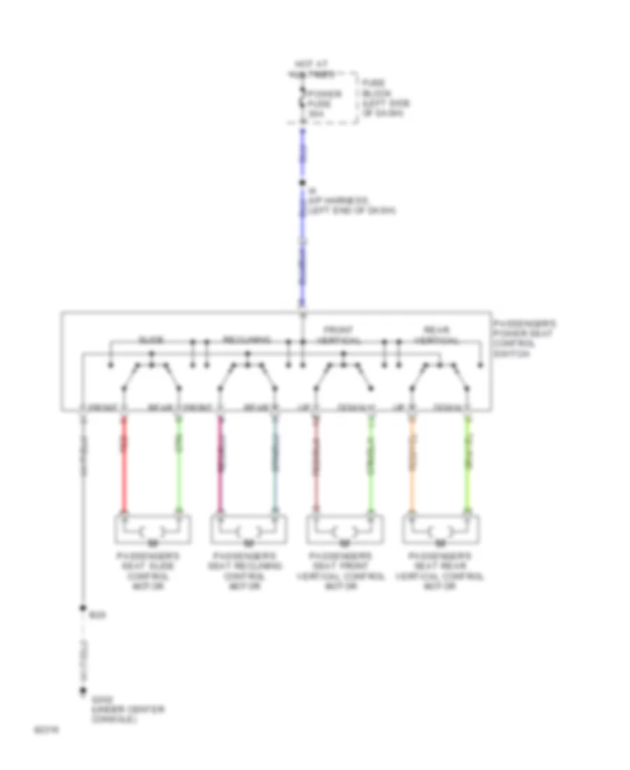
Passenger Power Seat Wiring Diagram for Toyota Land Cruiser 1995
List of elements for Passenger Power Seat Wiring Diagram for Toyota Land Cruiser 1995:
- B20
- Down
- Front
- Front vertical
- Fuse block (left side of dash)
- G302 (under center console)
- Hot at all times
- Left end of dash)
- Passenger's power seat control switch
- Passenger's seat front vertical control motor
- Passenger's seat rear vertical control motor
- Passenger's seat reclining control motor
- Passenger's seat slide control motor
- Power fuse 30a
- Rear
- Rear vertical
- Reclining
- Red
- Slide
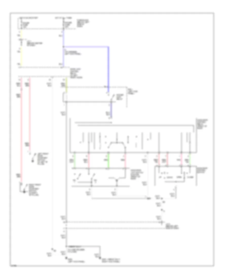
POWER TOP/SUNROOF
Power Top/Sunroof Wiring Diagrams for Toyota Land Cruiser 1995
List of elements for Power Top/Sunroof Wiring Diagrams for Toyota Land Cruiser 1995:
- (1996-97 only)
- Close
- Door lock control relay (in left front door)
- Down
- Fuse block (below left side of dash)
- G200 (left kick panel)
- G203 (right kick panel)
- Gauge fuse 10a
- Hot at all times
- Hot in on or start
- I3 (i/p harness, left kick panel)
- J/c 1 (behind center of dash)
- J/c 2 (behind left side of dash)
- Left front door courtesy switch (in left "b" pillar)
- Moon roof control relay (front of roof)
- Moon roof control switch
- Moon roof limit switch & motor (front of roof)
- No.
- Open
- Pnk
- Power fuse 30a
- Power main relay
- R/b 1 (left kick panel)
- Red
- Right front door courtesy switch (in right "b" pillar)
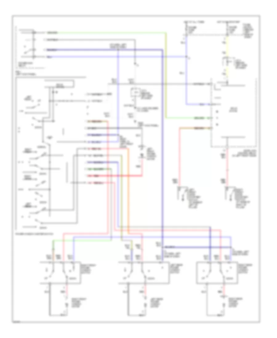
POWER WINDOWS
Power Window Wiring Diagram for Toyota Land Cruiser 1995
List of elements for Power Window Wiring Diagram for Toyota Land Cruiser 1995:
- (i/p harn, left side of dash) i3
- (land cruiser) (lx450)
- B4 (body harn, in left front door)
- Door lock control relay (in left front door)
- Down
- Fuse block (behind left side of dash)
- G200 (left kick panel)
- Gauge fuse 10a
- Hot at all times
- Hot in on or start
- I12 i13
- I2 (i/p harn, left side of dash)
- J/c 2 (behind left side of dash)
- J/c 4 (behind left side of dash)
- Left front
- Left front door courtesy switch (at base of left "b" pillar)
- Left front power window motor
- Left rear
- Left rear power window motor
- Left rear power window switch
- Lock
- Normal
- Power fuse 30a
- Power main relay
- Power window master switch
- R/b 1 (left kick panel)
- Red
- Right front
- Right front door courtesy switch (at base of right "b" pillar)
- Right front power window switch
- Right front power window motor
- Right rear
- Right rear power window motor
- Right rear power window switch
- Solid state
RADIO
Radio Wiring Diagrams, with Built-in Amplifier for Toyota Land Cruiser 1995
List of elements for Radio Wiring Diagrams, with Built-in Amplifier for Toyota Land Cruiser 1995:
- (right kick panel)
- Acc
- Amp+
- Ant
- B14
- B22
- Cig fuse 15a
- Cooling fan (for radio & player) (center of dash)
- Dome fuse 10a
- Fl+
- Fl-
- Fr+
- Fr-
- Fuse block (left side of dash)
- G200 (left kick panel)
- G203
- G302 (below center console)
- Gauge fuse 10a
- Gnd
- Hot at all times
- Hot in acc or on
- Hot in on or start
- I10
- I14
- Illum
- Interior lights system
- J/c 3
- J/c 4
- J/c 7
- Left front door speaker
- Left front speaker
- Left rear door speaker
- Left roof speaker
- Pnk
- Power antenna system
- R/b 2 (left side of engine compartment)
- Radio & player
- Red
- Right front door speaker
- Right front speaker
- Right rear door speaker
- Right roof speaker
- Rl+
- Rl-
- Rr+
- Rr-
- Wf+
- Wf-
- Woofer speaker
- Woofer speaker amplifier
Radio Wiring Diagrams, with Separate Amplifier for Toyota Land Cruiser 1995
List of elements for Radio Wiring Diagrams, with Separate Amplifier for Toyota Land Cruiser 1995:
- Acc
- Amp+
- Ant
- B14
- B22
- Beep
- Cig fuse 15a
- Cooling fan (for radio & player) (center of dash)
- Dome fuse 10a
- Fl+
- Fl-
- Fr+
- Fr-
- Fuse block (left side of dash)
- G200 (left kick panel)
- G203 (right kick panel)
- G302 (below center console)
- Gauge fuse 10a
- Gnd
- Hot at all times
- Hot in acc or on
- Hot in on or start
- I10
- I14
- Illum
- Interior lights system
- J/c 3
- J/c 4
- J/c 7
- Left front door speaker
- Left front speaker
- Left rear door speaker
- Left roof speaker
- Mute
- Pnk
- Power antenna system
- R/b 2 (left side of engine compartment)
- Radio & player
- Red
- Right front door speaker
- Right front speaker
- Right rear door speaker
- Right roof speaker
- Rl+
- Rl-
- Rr+
- Rr-
- S gmd
- S gnd
- S11
- S12
- Stereo component amplifier
- Wf+
- Wf-
- Woofer speaker
- Woofer speaker amplifier
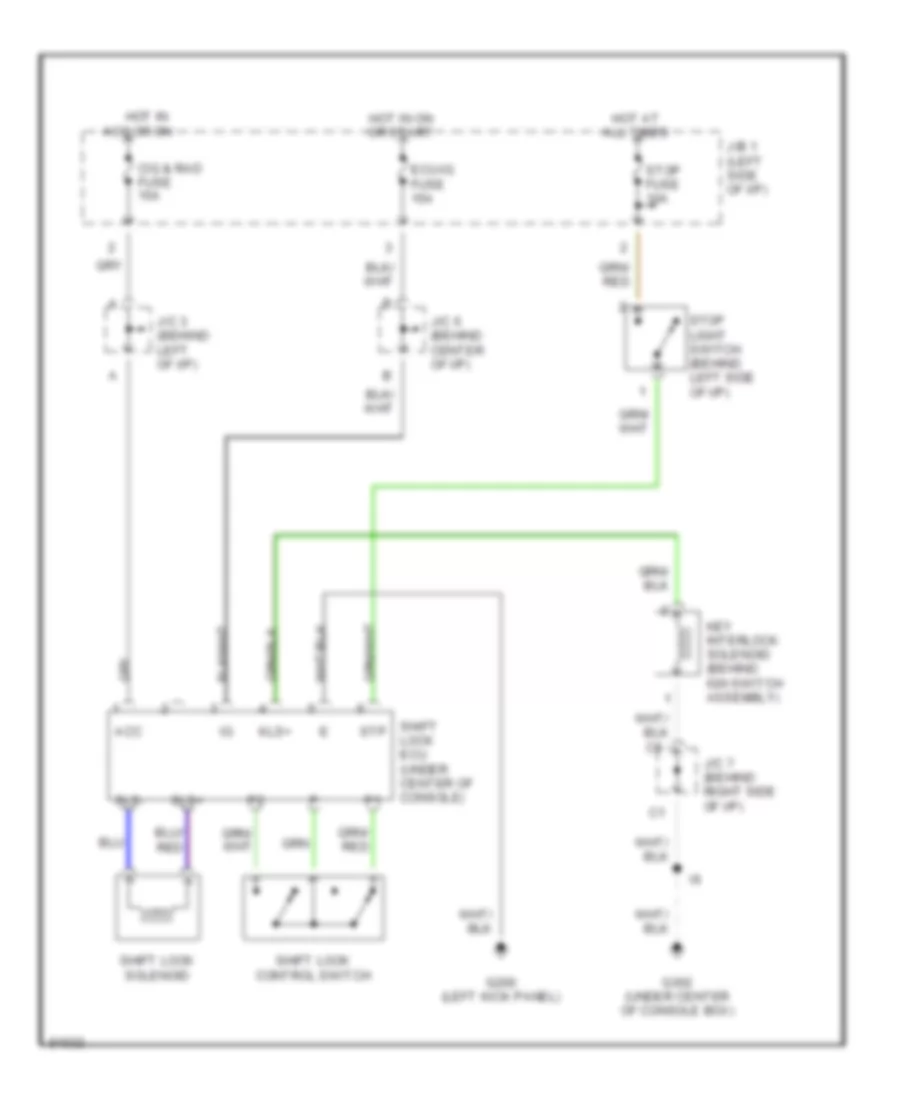
SHIFT INTERLOCKS
Shift Interlock Wiring Diagram for Toyota Land Cruiser 1995
List of elements for Shift Interlock Wiring Diagram for Toyota Land Cruiser 1995:
- Acc
- Cig & rad fuse 15a
- Ecu-ig fuse 15a
- G200 (left kick panel)
- G302 (under center of console box)
- Hot at all times
- Hot in acc or on
- Hot in on or start
- J/b 1 (left side of i/p)
- J/c 3 (behind left of i/p)
- J/c 6 (behind center of i/p)
- J/c 7 (behind right side of i/p)
- Key interlock solenoid (behind ign switch assembly)
- Kls+
- Shift lock control switch
- Shift lock ecu (under center of console)
- Shift lock solenoid
- Sls+
- Sls-
- Stop fuse 10a
- Stop light switch (behind left side of i/p)
- Stp
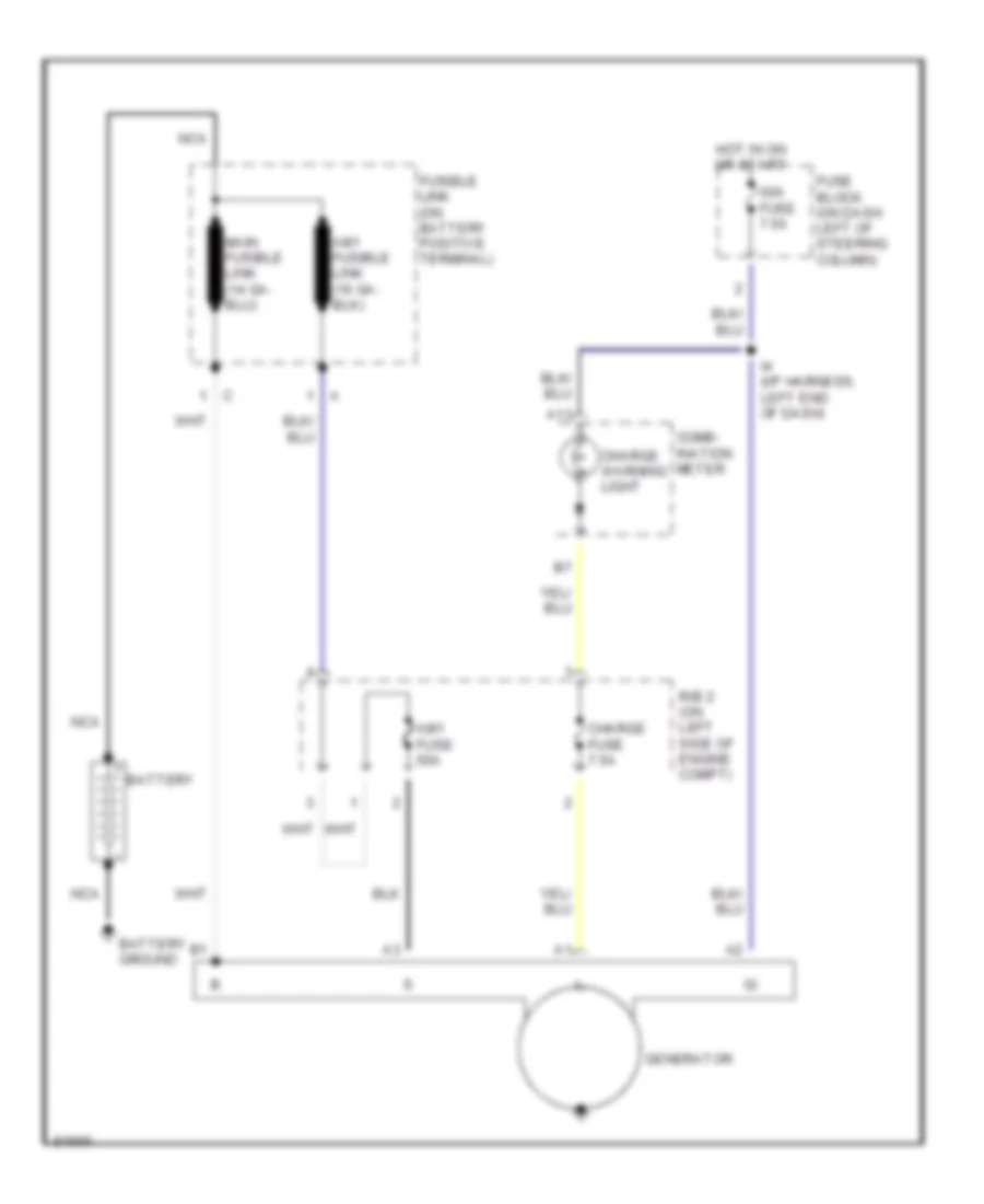
STARTING/CHARGING
Charging Wiring Diagram for Toyota Land Cruiser 1995
List of elements for Charging Wiring Diagram for Toyota Land Cruiser 1995:
- A13
- Am1 fuse 50a
- Battery
- Battery ground
- Charge fuse 7.5a
- Charge warning light
- Comb- ination meter
- Fuse block (on dash left of steering column)
- Fusible link (on battery positive terminal)
- Generator
- Hot in on or start
- I4 (i/p harness, left end of dash)
- Ign fuse 7.5a
- Nca
- R/b 2 (on left side of engine compt)
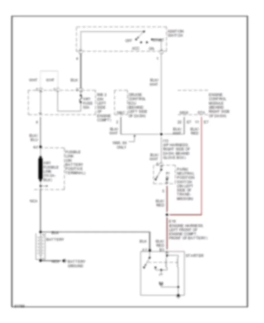
Starting Wiring Diagram for Toyota Land Cruiser 1995
List of elements for Starting Wiring Diagram for Toyota Land Cruiser 1995:
- 1995, 96 only
- Acc
- Am1 fuse 50a
- Battery
- Battery ground
- Cruise control ecu (behind left side of dash)
- E19 (engine harness, left front of engine compt, front of battery)
- Engine control module (behind right side of dash)
- Fusible link (on battery positive terminal)
- I13 (i/p harness, right side of dash, behind glove box)
- Ignition switch
- N&c
- Nca
- Nsw
- Off
- P/ n
- Park/ neutral position switch (on left side of trans- mission)
- R/b 2 (on left side of engine compt)
- Sta
- Start
- Starter
SUPPLEMENTAL RESTRAINTS
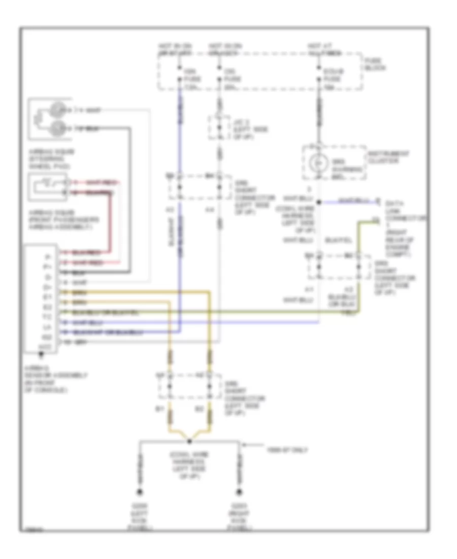
Supplemental Restraint Wiring Diagram for Toyota Land Cruiser 1995
List of elements for Supplemental Restraint Wiring Diagram for Toyota Land Cruiser 1995:
- (cowl wire harness, left side of i/p)
- 1996-97 only
- Acc
- Airbag sensor assembly (in front of console)
- Airbag squib (front passenger's airbag assembly)
- Airbag squib (steering wheel pad)
- Cig fuse 15a
- Data link connector (right rear of engine compt)
- Ecu-b fuse 10a
- Fuse block
- G200 (left kick panel)
- G203 (right kick panel)
- Hot at all times
- Hot in on or accy
- Hot in on or start
- Ig2
- Ign fuse 7.5a
- Instrument cluster
- J/c 3 (left side of i/p)
- Srs short connector (left side of i/p)
- Srs warning ind
TRANSMISSION
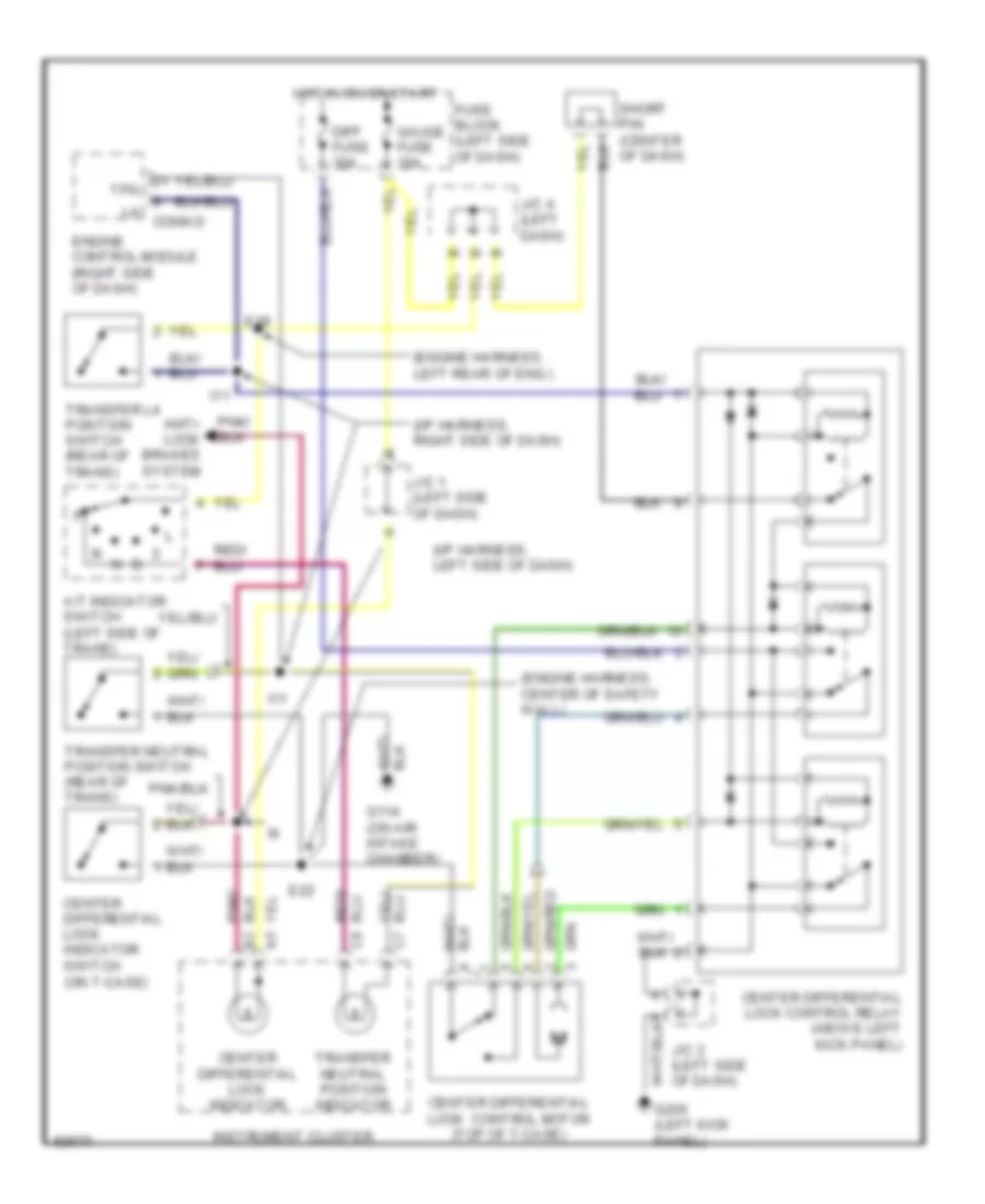
Center Differential Lock Wiring Diagram for Toyota Land Cruiser 1995
List of elements for Center Differential Lock Wiring Diagram for Toyota Land Cruiser 1995:
- (engine harness, center of safety wall)
- (engine harness, left rear of eng.)
- (i/p harness, left side of dash)
- (i/p harness, right side of dash)
- A/t indicator switch (left side of trans)
- Anti- lock brakes system
- Center differential lock control motor (top of t-case)
- Center differential lock control relay (above left kick panel)
- Center differential lock indicator
- Center differential lock indicator switch (on t-case)
- Conn d
- Diff fuse 30a
- E18
- E22
- Engine control module (right side of dash)
- Fuse block (left side of dash)
- G114 (on air intake chamber)
- Gauge fuse 10a
- Hot in on or start
- I11
- Instrument cluster
- J/c 1 (left side of dash)
- J/c 2 (left side of dash)
- J/c 4 (left dash)
- Short pin (center of dash)
- Tfn
- Transfer l4 position switch (rear of trans)
- Transfer neutral position indicator
- Transfer neutral position switch (rear of trans)
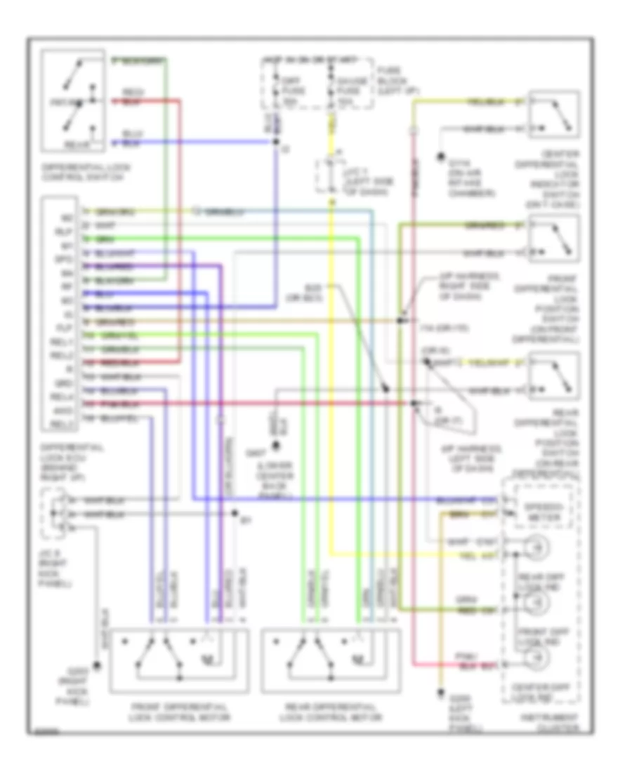
Front/Rear Differential Lock Wiring Diagram for Toyota Land Cruiser 1995
List of elements for Front/Rear Differential Lock Wiring Diagram for Toyota Land Cruiser 1995:
- rear differential lock position switch (on rear differential)
- (i/p harness, left side of dash)
- (i/p harness, right side of dash)
- (lower center back panel)
- (or i6) i5
- 4wd
- B25 (or b23)
- C10
- Center diff lock ind
- Center differential lock indicator switch (on t-case)
- Diff fuse 30a
- Differential lock control switch
- Differential lock ecu (behind right i/p)
- Flp
- Front diff lock ind
- Front differential lock control motor
- Front differential lock position switch (on front differential)
- Frt/rr
- Fuse block (left i/p)
- G114 (on air intake chamber)
- G200 (left kick panel)
- G203 (right kick panel)
- G407
- Gauge fuse 10a
- Grd
- Hot in on or start
- I14 (or i15)
- I6 (or i7)
- Instrument cluster
- J/c 1 (left side of dash)
- J/c 8 (right kick panel)
- Rear
- Rear diff lock ind
- Rear differential lock control motor
- Red
- Rel1
- Rel2
- Rel3
- Rel4
- Rlp
- Spd
- Speedo- meter
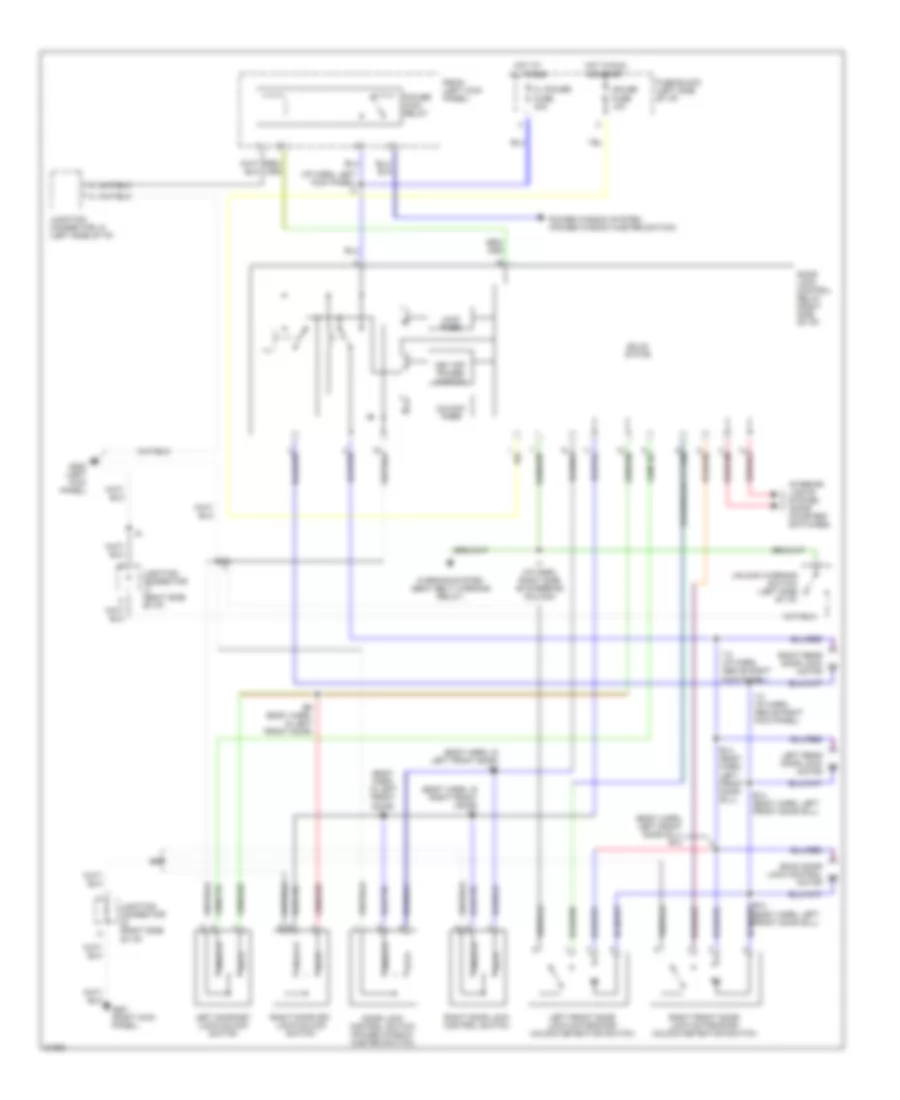
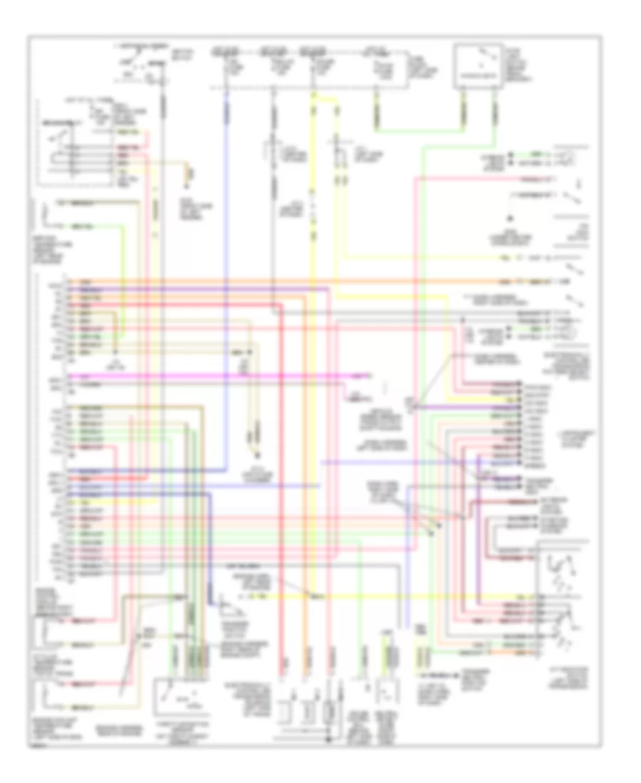
Transmission Wiring Diagram for Toyota Land Cruiser 1995
List of elements for Transmission Wiring Diagram for Toyota Land Cruiser 1995:
- (dash harn, right side of dash) i12 (or i13)
- (dash harness, center of dash)
- (dash harness, left side of dash)
- (dash harness, right side of dash)
- (engine harn, left rear of engine)
- (engine harness, rear of engine)
- (engine harness, right rear of engine compt)
- (or i10)
- (or i7) i6
- 1995,
- 2 indic
- 2nd
- 2nd strt
- A/t fluid temperature sensor (top of trans)
- A/t indicator switch (left side of transmission)
- Acc
- Cruise control ecu (behind left side of dash)
- D indic
- E16
- E18
- Ecu-ig fuse 15a
- Efi fuse 15a
- Efi main relay
- Egr gas temperature sensor (left rear of engine)
- Electronically controlled transmission pattern select switch
- Electronically controlled transmission solenoid (left side of trans)
- Engine control module (behind right side of dash)
- Engine coolant temperature sensor (left side of eng)
- Eo1
- Eo2
- Eo3
- Exterior lights system
- Fuse block (left side of dash)
- G100 (front side of left fender)
- G114 (air intake chamber)
- G302 (under center console box)
- Gauge fuse 10a
- Hold
- Hot at all times
- Hot in on or start
- I11 (or i12) (dash harn, right side of dash)
- I12 (or i13)
- I18 (or i19)
- Idl
- Ign fuse 75a
- Ignition switch
- Igsw
- Instrument cluster system
- Interior lights system
- J/c 1 (left side of dash)
- J/c 4 (center of dash)
- J/c 6 (center of dash)
- L indic
- Mrly
- N indic
- Neutral detect diode (right side of dash)
- No 1
- No 2
- No 3
- O/d indic
- O/d main switch
- Od1
- Od2
- Off
- P indic
- Pwr
- Pwr indic
- R indic
- R/b 2 (front side of left fender)
- Red
- Sp2+
- Sp2-
- Spd
- Speedo
- St1
- Start
- Starting/ charging system
- Stop fuse 10aa
- Stop light switch (brake pedal bracket)
- Stp
- Tfn
- Thg
- Throttle position sensor (on throttle body assembly)
- Thw
- Transfer neutral indic
- Transfer neutral position switch
- Transfer position switch
- Vcc
- Vehicle speed sensor (trans output shaft housing)
- Vta
WARNING SYSTEMS
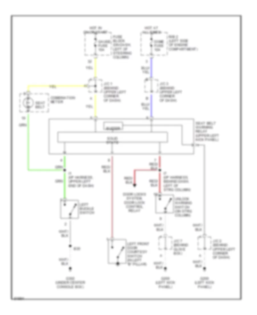
Warning System Wiring Diagrams for Toyota Land Cruiser 1995
List of elements for Warning System Wiring Diagrams for Toyota Land Cruiser 1995:
- B35
- Buzzer
- Combination meter
- Dome fuse 10a
- Door locks system, door lock control relay
- Fuse block (on dash, left of steering column)
- G200 (left kick panel)
- G302 (under center console box)
- Gauge fuse 10a
- Hot at all times
- Hot in on or start
- I1 (i/p harness, upper left end of dash)
- I7 (i/p harness, behind dash, left of strg column)
- J/c 1 (behind upper left corner of dash)
- J/c 2 (behind upper left corner of dash)
- J/c 3 (behind upper left corner of dash)
- J/c 7 (behind glove box)
- Left buckle switch
- Left front door courtesy switch (in left "b" pillar)
- R/b 2 (left side of engine compartment)
- Seat belt
- Seat belt warning relay (upper left kick panel)
- Solid state
- Unlock warning switch (on strg column)
WIPER/WASHER
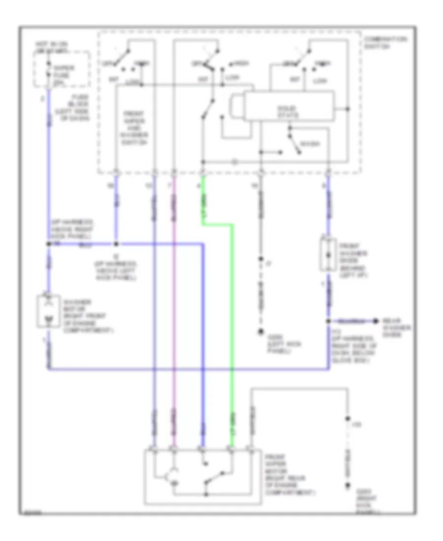
Front Washer/Wiper Wiring Diagram for Toyota Land Cruiser 1995
List of elements for Front Washer/Wiper Wiring Diagram for Toyota Land Cruiser 1995:
- (behind left i/p)
- (i/p harness, above right kick panel) i15
- Combination switch
- Front washer diode
- Front wiper and washer switch
- Front wiper motor (right rear of engine compartment)
- Fuse block (left side of dash)
- G200 (left kick panel)
- G203 (right kick panel)
- High
- Hot in on or start
- I13 (i/p harness, right side of dash, below glove box)
- I15
- I2 (i/p harness, above left kick panel)
- Int
- Int low
- Low
- Off
- Rear washer diode
- Solid state
- Wash
- Washer motor (right front of engine compartment)
- Wiper fuse 20a
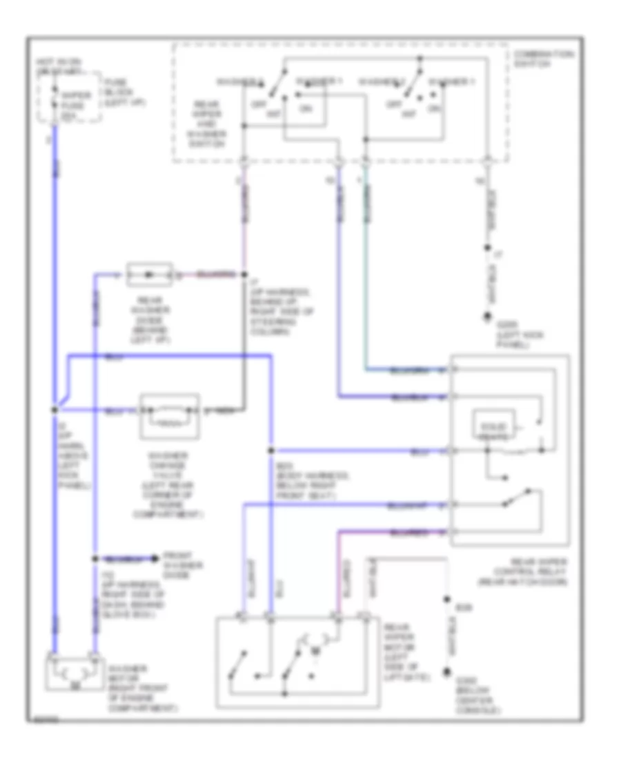
Rear Washer/Wiper Wiring Diagram for Toyota Land Cruiser 1995
List of elements for Rear Washer/Wiper Wiring Diagram for Toyota Land Cruiser 1995:
- B20 (body harness, below right front seat)
- B28
- Combination switch
- Front washer diode
- Fuse block (left i/p)
- G200 (left kick panel)
- G302 (below center console)
- Hot in on or start
- I12 (i/p harness, right side of dash, behind glove box)
- I2 (i/p harn, above left kick panel)
- I7 (i/p harness, behind i/p, right side of steering column)
- Int
- Nca
- Off
- Rear washer diode (behind left i/p)
- Rear wiper and washer switch
- Rear wiper control relay (rear hatch door)
- Rear wiper motor (left side of liftgate)
- Solid state
- Washer 1
- Washer 2
- Washer change valve (left rear corner of engine compartment)
- Washer motor (right front of engine compartment)
- Wiper fuse 20a

 Čeština
 Dansk
Dansk Ελληνικά
 English
 English
 Español
 Suomi
Suomi Français
 Français
 עברית
עברית Hrvatski
 Magyar
 Italiano
 日本語
日本語 한국어
한국어 Nederlands
 Polski
 Português
 Português
 Română
 Русский
 Slovenčina
 Slovenščina
 Svenska
 Türkçe
 中文 (中国)