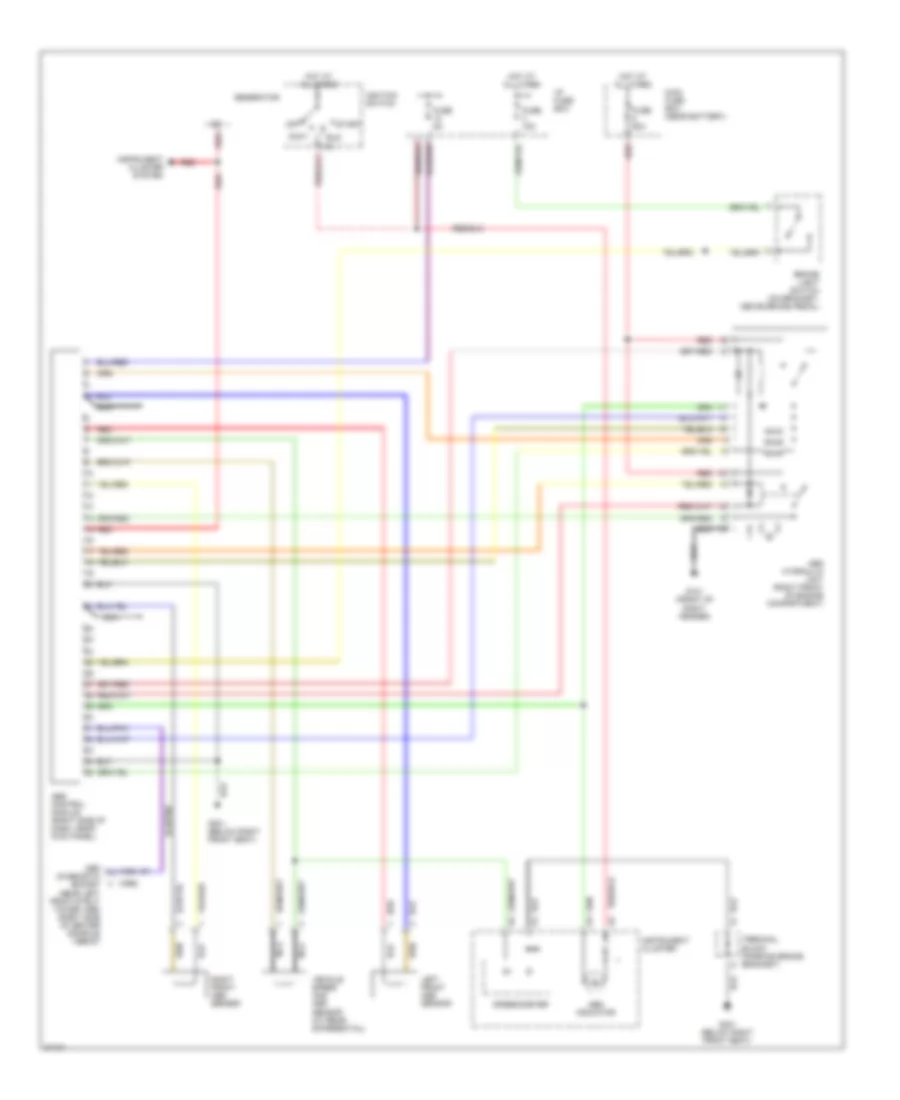
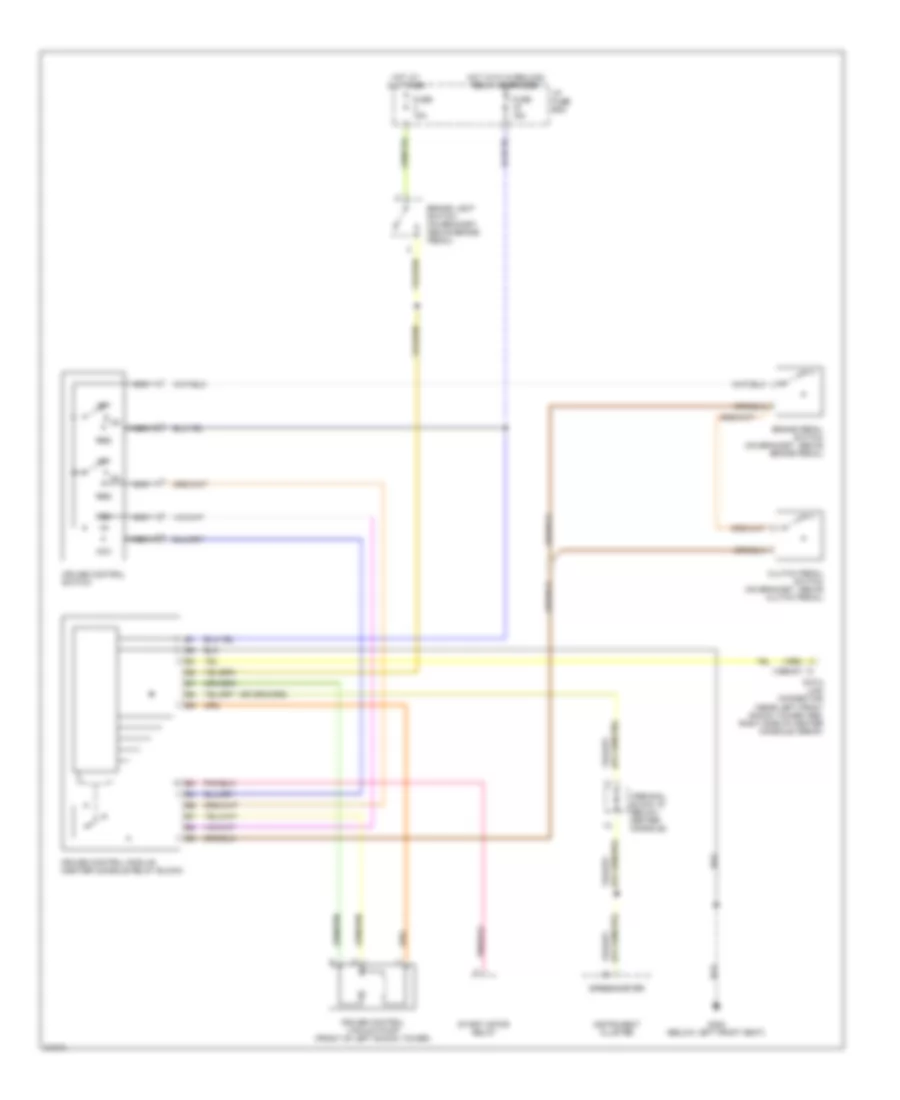
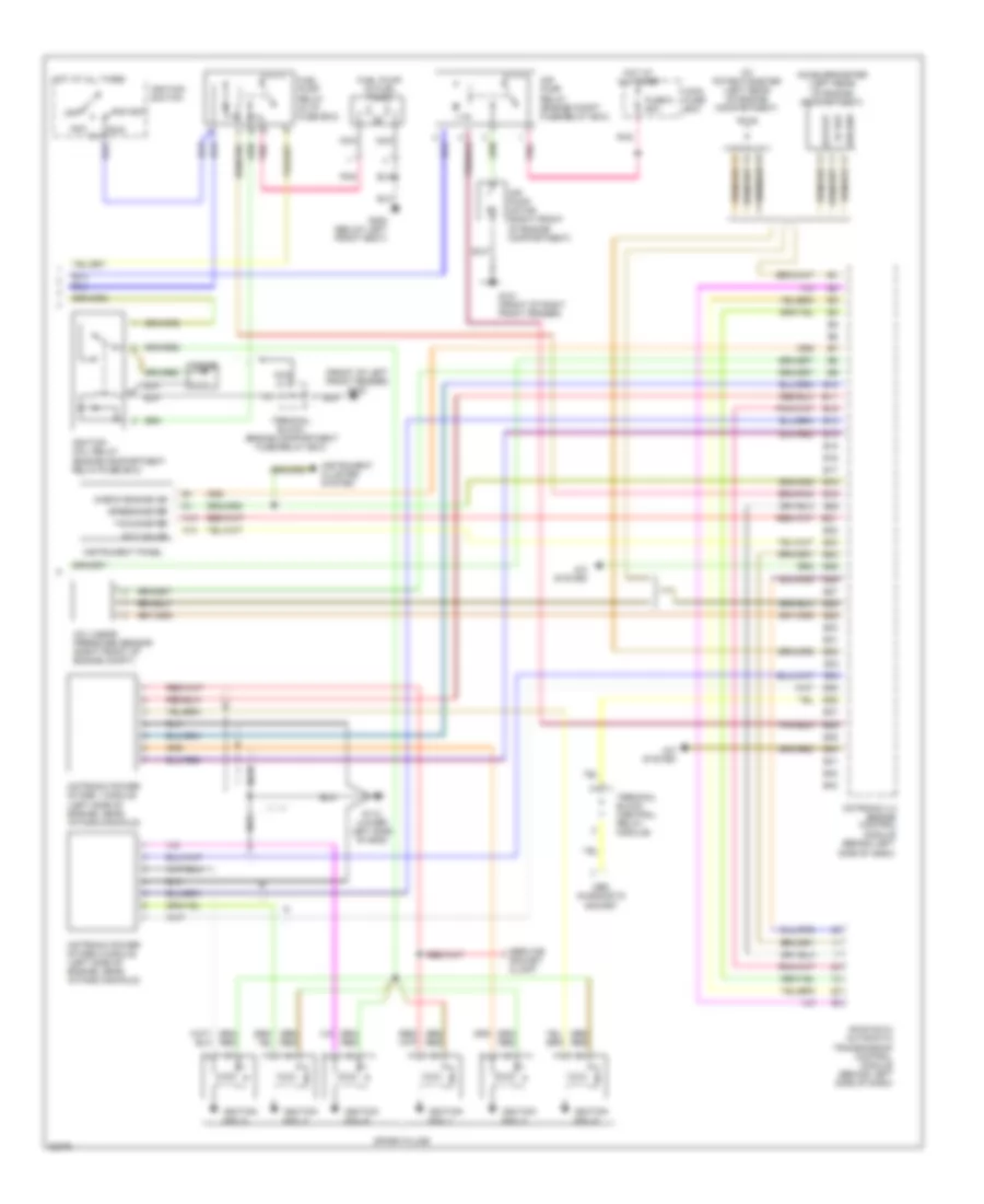
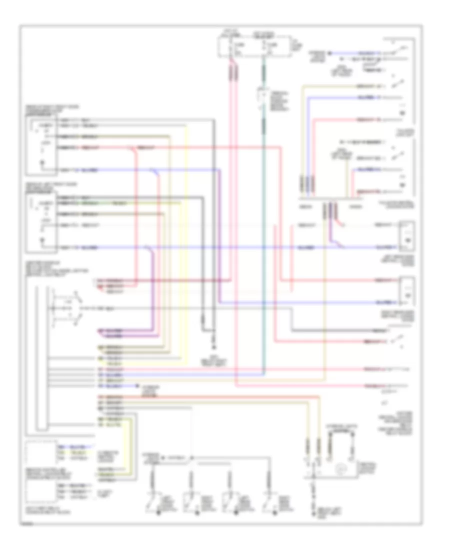
AIR CONDITIONING
Air Conditioning Wiring Diagrams for Volvo 960 1997
 https://portal-diagnostov.com/license.html
Automotive Electricians Portal FZCO
Automotive Electricians Portal FZCO
https://portal-diagnostov.com/license.html
https://portal-diagnostov.com/license.html
Automotive Electricians Portal FZCO
Automotive Electricians Portal FZCO
List of elements for Air Conditioning Wiring Diagrams for Volvo 960 1997:
- (left kick panel)
- A/c compressor
- A/c linear pressure sensor
- A/c low pressure sensor (on accumulator)
- A10
- A11
- A12
- A13
- A14
- A15
- A16
- A17
- A18
- A19
- A20
- A21
- A22
- A23
- A24
- A25
- A26
- A27
- A28
- A29
- A30
- Ambient temperature sensor (behind right side of i/p)
- Automatic climate control a/c relay (in engine compartment relay/fuse box)
- B10
- Blower motor
- Box
- Cabin temperature sensor (on overhead console)
- Charging system (generator)
- Cooling fan motor
- Digital output
- Ecc control module (center of i/p)
- Ecc operating solenoids
- Engine compartment
- Engine control module
- Engine coolant temperature sensor (behind left side of i/p)
- Engine cooling fan relay (right front of engine compartment)
- Fan control module (behind right side of i/p)
- Fuse
- Fuse 11/16 15a
- Fuse 11/2 15a
- Fuse 11/7 20a
- Fusible link 7
- G107 (behind right headlight)
- G301 (below right front seat)
- Hot at all times
- Hot in on
- Instrument panel
- Pnk
- Red
- Relay/fuse box
- Servo motor (behind center of i/p)
- Solar sensor (top right of i/p)
ANTI-LOCK BRAKES
Anti-lock Brake Wiring Diagrams for Volvo 960 1997
List of elements for Anti-lock Brake Wiring Diagrams for Volvo 960 1997:
- (1995)
- (1996, 97)
- 15a
- Abs control module (right side of dash, near kick panel)
- Abs hydraulic unit (right front of engine compartment)
- Abs indicator
- Accy
- Brake light switch (on bracket, above brake pedal)
- Fuse 15a
- Fuse 50a
- Fuse 5a
- G101 (front of right fender)
- G301 (below right front seat)
- Generator
- Hot at all times
- I/p fuse box
- Ignition switch
- Instrument cluster
- Instrument cluster system
- Left front abs sensor
- Main fuse box (near battery)
- Nca
- Obd diagnostic socket (near left front strut tower 1995) (right side of center console 1996-97)
- Off
- Red
- Right front abs sensor
- Run
- Speedometer
- Start
- Terminal block (parking brake bracket)
- Vehicle speed and abs sensor (at rear differential)
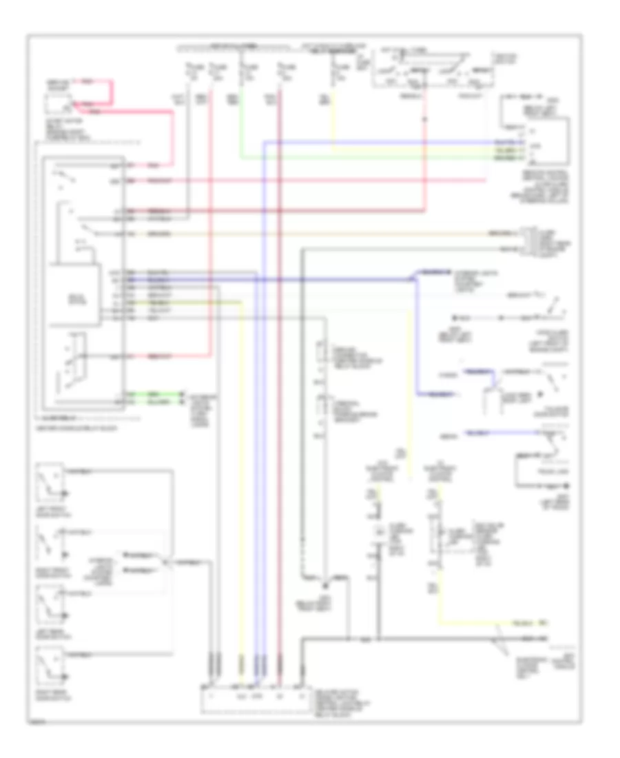
ANTI-THEFT
Base Anti-theft Wiring Diagram for Volvo 960 1997
List of elements for Base Anti-theft Wiring Diagram for Volvo 960 1997:
- (below left front seat)
- 15a
- 30k
- 31b
- 50e
- 50f
- Acc
- Al2
- Alarm horn (right rear of engine compt)
- Alarm relay
- Alarm warning led
- Alarm warning led (top right of i/p)
- Atr
- Center console relay block
- Delayed action inside lighting/ central lock relay (center console relay block)
- Ecc control module
- Ecc solar sensor/ alarm warning led (top right of i/p)
- Electronic climate control only
- Exterior lights system (turn- signal lamps)
- Fuse 10a
- Fuse 15a
- Fuse 20a
- Fuse 5a
- G300
- G300 (below left front seat)
- G301 (below right front seat)
- G407 (left rear of trunk)
- Ground connection (center console relay block)
- Hood alarm switch (left front of engine compt)
- Hot at all times
- Hot in run w/ overload relay energized
- I/p fuse box
- Ignition switch
- Interior lights system (courtesy lamps)
- Interior lights system (courtesy lights)
- Left front door switch
- Left rear door switch
- Load area roof light
- Lock
- Nca
- Pnk
- Remote control central locking & car alarm control module (behind dash, left of steering column)
- Right front door switch
- Right rear door switch
- Run
- Sedan
- Service socket
- Solid state
- Start
- Start motor relay (engine compt fuse/relay box)
- Tailgate door switch
- Terminal block (parking brake bracket)
- Trunk lock
- W/ electronic climate control
- W/o electronic climate control
- Wagon
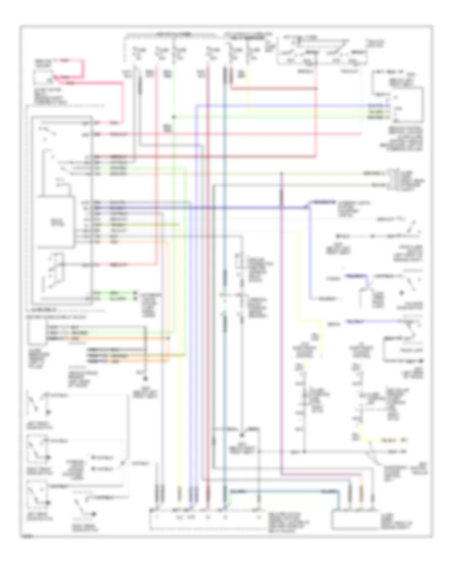
Guard Alarm II Wiring Diagram for Volvo 960 1997
List of elements for Guard Alarm II Wiring Diagram for Volvo 960 1997:
- (below left front seat)
- 15a
- 30k
- 31b
- 50e
- 50f
- Acc
- Al2
- Alarm horn (right rear of engine compt)
- Alarm relay
- Alarm siren (right front of engine compt)
- Alarm warning led
- Alarm warning led (top right of i/p)
- Atr
- Center console relay block
- Delayed action inside lighting/ central lock relay (center console relay block)
- Ecc control module
- Ecc solar sensor/ alarm warning led (top right of i/p)
- Electronic climate control only
- Exterior lights system (turn- signal lamps)
- Fuse 10a
- Fuse 15a
- Fuse 20a
- Fuse 5a
- G300
- G300 (below left front seat)
- G301 (below right front seat)
- G407 (left rear of trunk)
- Glass breakage sensor (left "a" pillar)
- Ground connection (center console relay block)
- Hood alarm switch (left front of engine compt)
- Hot at all times
- Hot in run w/ overload relay energized
- I/p fuse box
- Ignition switch
- Interior lights system (courtesy lamps)
- Interior lights system (courtesy lights)
- Left front door switch
- Left rear door switch
- Load area roof light
- Lock
- Nca
- Pnk
- Remote control central locking & car alarm control module (behind dash, left of steering column)
- Right front door switch
- Right rear door switch
- Run
- Sedan
- Service socket
- Solid state
- Start
- Start motor relay (engine compt fuse/relay box)
- Tailgate door switch
- Terminal block (parking brake bracket)
- Trunk lock
- Vehicle angle sensor (left rear of trunk)
- W/ electronic climate control
- W/o electronic climate control
- Wagon
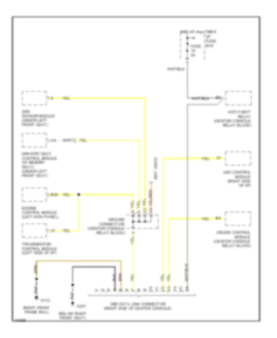
COMPUTER DATA LINES
Computer Data Lines for Volvo 960 1997
List of elements for Computer Data Lines for Volvo 960 1997:
- (below right front seat)
- (not used)
- (right front frame rail)
- Abs control module (right side of i/p)
- Anti-theft relay (center console relay block)
- B36
- Cruise control module (center console relay block)
- Driver's seat control module (w/ memory seat) (under left front seat)
- Engine control module (left kick panel)
- Fuse 5a
- G113
- G301
- Ground connection (center console relay block)
- Hot at all times
- I/p fuse box
- Obd data link connector (right side of center console)
- Srs sensor module (under left front seat)
- Transmission control module (left side of i/p)
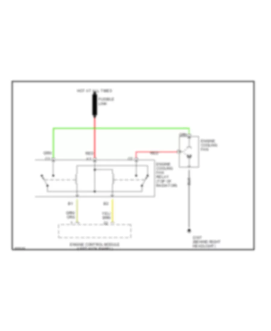
COOLING FAN
Cooling Fan Wiring Diagram for Volvo 960 1997
List of elements for Cooling Fan Wiring Diagram for Volvo 960 1997:
- Engine control module (left kick panel)
- Engine cooling fan
- Engine cooling fan relay (top of radiator)
- Fusible link
- G107 (behind right headlight)
- Hot at all times
- Red
CRUISE CONTROL
Cruise Control Wiring Diagram for Volvo 960 1997
List of elements for Cruise Control Wiring Diagram for Volvo 960 1997:
- (1995)
- (1996-97)
- Acc
- Brake light switch (on bracket, above brake pedal)
- Brake pedal switch (on bracket, above brake pedal)
- Clutch pedal switch (on bracket, above clutch pedal)
- Cruise control module (center console relay block)
- Cruise control switch
- Cruise control vacuum pump (front of left shock tower)
- Data link connector (near left front shock tower-1995, right side of center console-1996-97)
- Dec
- Fuse 15a
- G300 (below left front seat)
- Hot at all times
- Hot with overload relay energized
- I/p fuse box
- Instrument cluster
- Nca
- Off
- Res
- Speedometer
- Start motor relay
- Terminal block 19 (below center console)
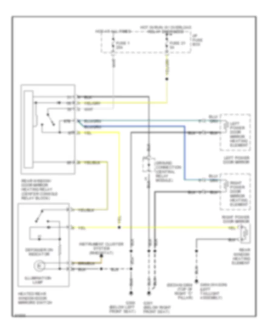
DEFOGGERS
Defogger Wiring Diagram for Volvo 960 1997
List of elements for Defogger Wiring Diagram for Volvo 960 1997:
- (sedan) g904 (top of right "c" pillar)
- 15i
- 87b
- Defogger on indicator
- Fuse 1 25a
- Fuse 21 5a
- G300 (below left front seat)
- G301 (below right front seat)
- G404 (wagon) (left taillight assembly)
- Ground connection (central relay module)
- Heated rear window/door mirrors switch
- Hot at all times
- Hot in run, w/ overload relay energized
- I/p fuse box
- Illumination lamp
- Instrument cluster system (rheostat)
- Left power door mirror
- Left power door mirror heating element
- Rear window heating element
- Rear window/ door mirror heating relay (center console relay block)
- Right power door mirror
- Right power door mirror heating element
ENGINE PERFORMANCE
2.9L
2.9L, Engine Performance Wiring Diagrams (1 of 2) for Volvo 960 1997
List of elements for 2.9L, Engine Performance Wiring Diagrams (1 of 2) for Volvo 960 1997:
- (front center of eng compt)
- (left front of eng compt) evap valve
- A10
- A11
- A12
- A13
- A14
- A15
- A16
- A17
- A18
- A19
- A20
- A21
- A22
- A23
- A24
- A25
- A26
- A27
- A28
- A29
- A30
- A31
- A32
- A33
- A34
- A35
- A36
- A37
- A38
- A39
- A40
- A41
- A42
- A43
- Aux. air intake solenoid
- Camshaft position sensor (top front of engine)
- Engine compartment relay/ fuse box
- Engine coolant temperature sensor (right front of eng)
- Engine cooling fan relay
- Front heated oxygen sensor (on exhaust pipe, before converter)
- Front knock sensor (ks) (front of eng block)
- Fuel injection system main relay (engine compartment fuse/relay box)
- Fuel injectors
- Fuse 15a
- Fuse 25a
- Fuse 4 50a
- Fuse 5a
- G113 (base of left front strut tower)
- Hot at all times
- Idle air control valve (left front of engine)
- Impulse sensor (lower front of engine)
- Main fuse box
- Mass air flow (maf) sensor (on air intake duct)
- Motronic 4.4 engine control module (behind left side of dash)
- Nca
- Pnk
- Rear heated oxygen sensor (on exhaust pipe, after converter)
- Rear knock sensor (ks) (left front of eng block)
- Red
- Throttle position (tp) sensor (left front of eng)
2.9L, Engine Performance Wiring Diagrams (2 of 2) for Volvo 960 1997
List of elements for 2.9L, Engine Performance Wiring Diagrams (2 of 2) for Volvo 960 1997:
- (front of left front fender) g100
- 5v ref
- A/c linear pressure sensor (right front of engine compt)
- A/c sysyem
- A13
- A14
- Acc
- Accelerometer (left rear of engine compartment)
- Air pump motor (right front of engine compartment)
- Air pump relay (engine compt fuse/relay box)
- Aw30-40/43 automatic transmission control module (behind left side of dash)
- B10
- B11
- B12
- B13
- B14
- B15
- B16
- B17
- B18
- B19
- B20
- B21
- B22
- B23
- B24
- B25
- B26
- B27
- B28
- B29
- B30
- B31
- B32
- B33
- B34
- B35
- B36
- B37
- B38
- B39
- B40
- B41
- B42
- B43
- Check engine ind
- Co potentiometer (left rear of engine compartment)
- Diode
- Ect gauge
- Fuel pump (in fuel tank)
- Fuel pump relay (in i/p fuse box)
- Fuse 6 50a
- G101 (front of right front fender)
- G112 (lower left side of eng)
- G300 (below left front seat)
- Ground
- Hot at all times
- Ignition coil 1
- Ignition coil 2
- Ignition coil 3
- Ignition coil 4
- Ignition coil 5
- Ignition coil 6
- Ignition coil relay (engine compartment relay/fuse box)
- Ignition switch
- Instrument cluster system
- Instrument panel
- Main fuse box
- Motronic 4.4 engine control module (behind left side of dash)
- Motronic power stage 1 module (left side of engine, near intake manifold)
- Motronic power stage 2 module (left side of engine, near intake manifold)
- Nca
- Obd diagnostic socket
- Off
- Output
- Pnk
- Run
- Service socket clamp
- Spark plugs
- Speedometer
- Start
- Tachometer
- Terminal block (central relay module)
- Terminal block (engine compartment fuse/relay box)
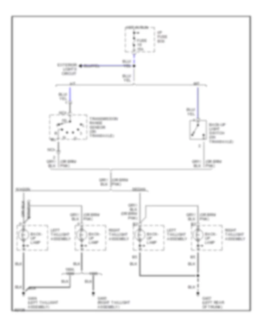
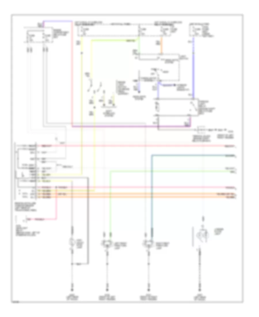
EXTERIOR LIGHTS
Back-up Lamps Wiring Diagram for Volvo 960 1997
List of elements for Back-up Lamps Wiring Diagram for Volvo 960 1997:
- 15i
- 1996,
- A/t
- Back- up lamp
- Back-up light switch (on transaxle)
- Exterior lights circuit
- Fuse 15a
- G404 (left taillight assembly)
- G405 (right taillight assembly)
- G407 (left rear of trunk)
- Hot in run
- I/p fuse box
- Left taillight assembly
- M/t
- Nca
- Pnk)
- Right taillight assembly
- Sedan
- Transmission range sensor (on transaxle)
- Wagon
Exterior Lamps Wiring Diagram, Sedan (1 of 2) for Volvo 960 1997
List of elements for Exterior Lamps Wiring Diagram, Sedan (1 of 2) for Volvo 960 1997:
- (front of left front fender)
- 15i
- 54h
- 54l
- 54r
- 56b
- 58a
- 58b
- 58c
- 58la
- 58lb
- 58ra
- 58rb
- Brake light switch (on brake pedal support)
- Engine compartment relay/fuse box
- Fuse 15a
- Fuse 30a
- Fuse 5a
- G100
- G100 (front of left front fender)
- G101 (front of right front fender)
- G407 (left rear of trunk)
- Head
- Headlights system
- High- mount stop lamp
- Hot at all times
- Hot in run, w/ overload relay energized
- I/p fuse box
- Interior lights (rheostat)
- Left front park/turn lamp
- License plate light
- Light switch
- Main fuse box (near battery)
- Main headlight relay (behind dash, left of steering column)
- Off
- Park
- Parking light relay (engine compt relay/fuse box)
- Rear bulb failure warning sensor (left rear of trunk/cargo area)
- Right front park/turn lamp
- Shift interlock system
- Terminal block (engine compt. relay/fuse box)
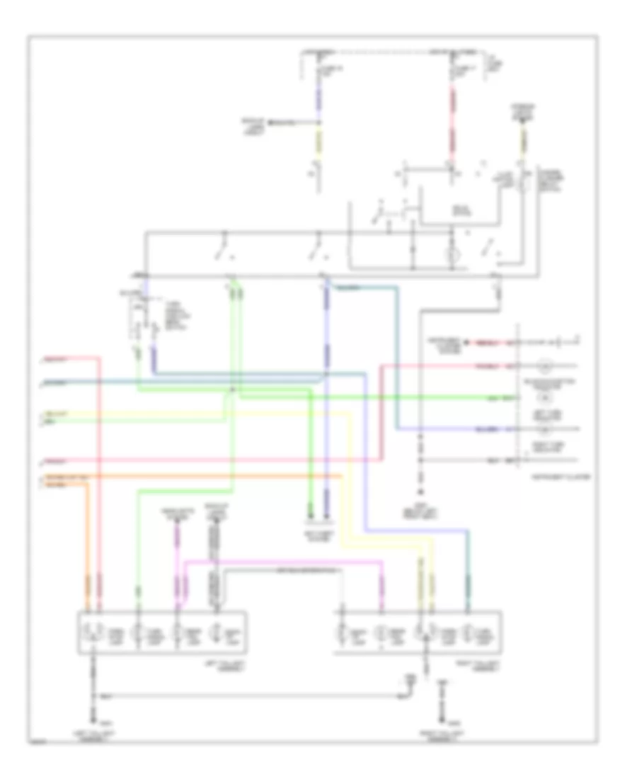
Exterior Lamps Wiring Diagram, Sedan (2 of 2) for Volvo 960 1997
List of elements for Exterior Lamps Wiring Diagram, Sedan (2 of 2) for Volvo 960 1997:
- (left rear of trunk)
- 15i
- 49a
- Anti-theft system
- B14
- Back- up lamp
- Back-up lamps circuit
- Bulb malfunction
- Fuse 17 20a
- Fuse 19 15a
- G300 (below left front seat)
- G407
- Hazard flasher relay/ switch
- Headlights system
- Hot at all times
- Hot in run
- I/p fuse box
- Illum- ination lamp
- Indicator
- Instrument cluster
- Instrument cluster system
- Interior lights system
- Left taillight assembly
- Left turn indicator
- Park lamp
- Rear fog lamp
- Right taillight assembly
- Right turn indicator
- Solid state
- Stop lamp
- Turn signal lamp
- Turn signal/ high-low beam switch
Exterior Lamps Wiring Diagram, Wagon (1 of 2) for Volvo 960 1997
List of elements for Exterior Lamps Wiring Diagram, Wagon (1 of 2) for Volvo 960 1997:
- (front of left front fender)
- 15i
- 1995 only
- 54h
- 54l
- 54r
- 56b
- 58a
- 58b
- 58c
- 58la
- 58lb
- 58ra
- 58rb
- Brake light switch (on brake pedal support)
- Engine compartment relay/fuse box
- Fuse 15a
- Fuse 30a
- Fuse 5a
- G100
- G100 (front of left front fender)
- G101 (front of right front fender)
- G407 (left rear of trunk)
- Head
- Headlights system
- High- mount stop lamp
- Hot at all times
- Hot in run, w/ overload relay energized
- I/p fuse box
- Interior lights (rheostat)
- Left front park/turn lamp
- License plate light
- Light switch
- Main fuse box (near battery)
- Main headlight relay (behind dash, left of steering column)
- Off
- Park
- Parking light relay (engine compt relay/fuse box)
- Rear bulb failure warning sensor (left rear of trunk/cargo area)
- Right front park/turn lamp
- Shift interlock system
- Terminal block (engine compt. relay/fuse box)
Exterior Lamps Wiring Diagram, Wagon (2 of 2) for Volvo 960 1997
List of elements for Exterior Lamps Wiring Diagram, Wagon (2 of 2) for Volvo 960 1997:
- (left taillight assembly)
- (right taillight assembly)
- 15i
- 1996,
- 49a
- Anti-theft system
- B14
- Back- up lamp
- Back-up lamps circuit
- Bulb malfunction
- Fuse 17 20a
- Fuse 19 15a
- G300 (below left front seat)
- G404
- G405
- Hazard flasher relay/ switch
- Headlights system
- Hot at all times
- Hot in run
- I/p fuse box
- Illum- ination lamp
- Indicator
- Instrument cluster
- Instrument cluster system
- Interior lights system
- Left taillight assembly
- Left turn indicator
- Park/ stop lamp
- Rear fog lamp
- Right taillight assembly
- Right turn indicator
- Solid state
- Turn signal lamp
- Turn signal/ high-low beam switch
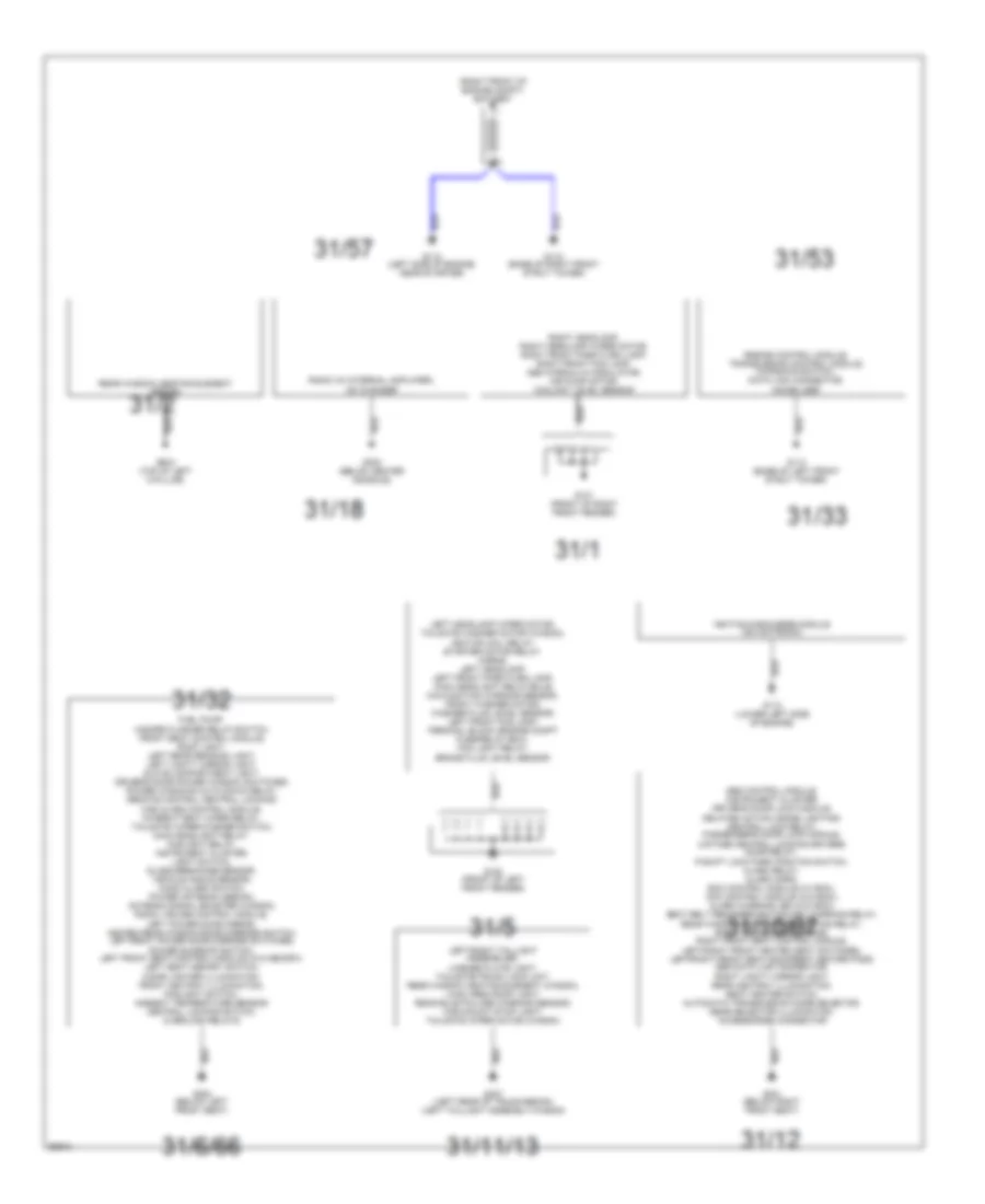
GROUND DISTRIBUTION
Ground Distribution Wiring Diagram for Volvo 960 1997
List of elements for Ground Distribution Wiring Diagram for Volvo 960 1997:
- (right front of engine compt) battery
- 31/1
- 31/11/13
- 31/12
- 31/18
- 31/2
- 31/32
- 31/33
- 31/5
- 31/53
- 31/57
- 31/6/66
- Abs control module, instrument cluster, driver's door lock module, delayed action inside lighting/ central lock relay, passenger's door lock module, 2-stage central locking driver's door relay, p-shift lock park position switch, alarm relay, alarm horn, ecc control module (w/ ecc), mcc control module (w/o ecc), alarm warning led (w/o ecc), seat belt reminder/ignition key warning relay, 31/10/67 rear window/door mirror heating relay, right power door mirror, right front seat control module, left/right front heated seat switches, left/right front seat backrest heater pads, obd data link connector, right vanity mirror light, rear ashtray illumination, seat heater switch, automatic transmission mode selector, gear selector illumination, accessories connector
- Engine control module, transmission control module, kickdown switch, data link connector, immobilizer
- Fuel pump, hazard flasher relay/switch, front seat control module, roof light, left rear reading light, left vanity mirror light, glove compartment light, driver's door power window switches, power windows auto down relay, remote control central locking/ car alarm control module, intermittent wiper relay, tailgate wiper/washer switch, main headlight relay, foglight relay, instrument cluster, light switch, glass breakage sensor, vehicle angle sensor, hood alarm switch, power antenna (sedan), antenna signal booster (wagon), radio, cruise control module, left power door mirror, heated rear window/door mirrors switch, left/right power door mirrors switches, power sunroof switch, left front seat control module (w/o memory), left seat memory switch, cigar lighter illumination, front ashtray illumination, foglight switch, ambient temperature sensor, central locking switch, overload relays
- G100 (front of left front fender)
- G101 (front of right front fender)
- G112 (left side of engine, near starter)
- G112 (lower left side of engine)
- G113 (base of left front strut tower)
- G118 (base of right front strut tower)
- G300 (below left front seat)
- G301 (below right front seat)
- G302 (below center console)
- G407 (left rear of trunk-sedan) (left taillight assembly-wagon)
- G904 (top of left c-pillar)
- Ignition discharge module idm (motronic)
- Left headlamp wiper motor, tailgate washer motor (wagon), ignition coil relay, starter motor relay, horns, left headlamp, left front park/turn lamp, main headlight relay/bulb malfunction warning sensor, front washer motor, washer fluid level sensor, left front fog lamp, terminal block (engine compt fuse/relay box), fog light relay, brake fluid level sensor
- Left/right taillight assemblies, license plate light, tailgate/trunk lock unit, rear window heating element (wagon), load area roof light, rear bulb failure warning sensor, high-mount stop light, tailgate wiper motor (wagon)
- Radio (w/ internal amplifier), cd changer
- Rear window heating element (sedan)
- Right headlamp, right headlamp wiper motor, right front park/turn lamp, right front fog lamp, abs hydraulic modulator, air pump motor, coolant level sensor
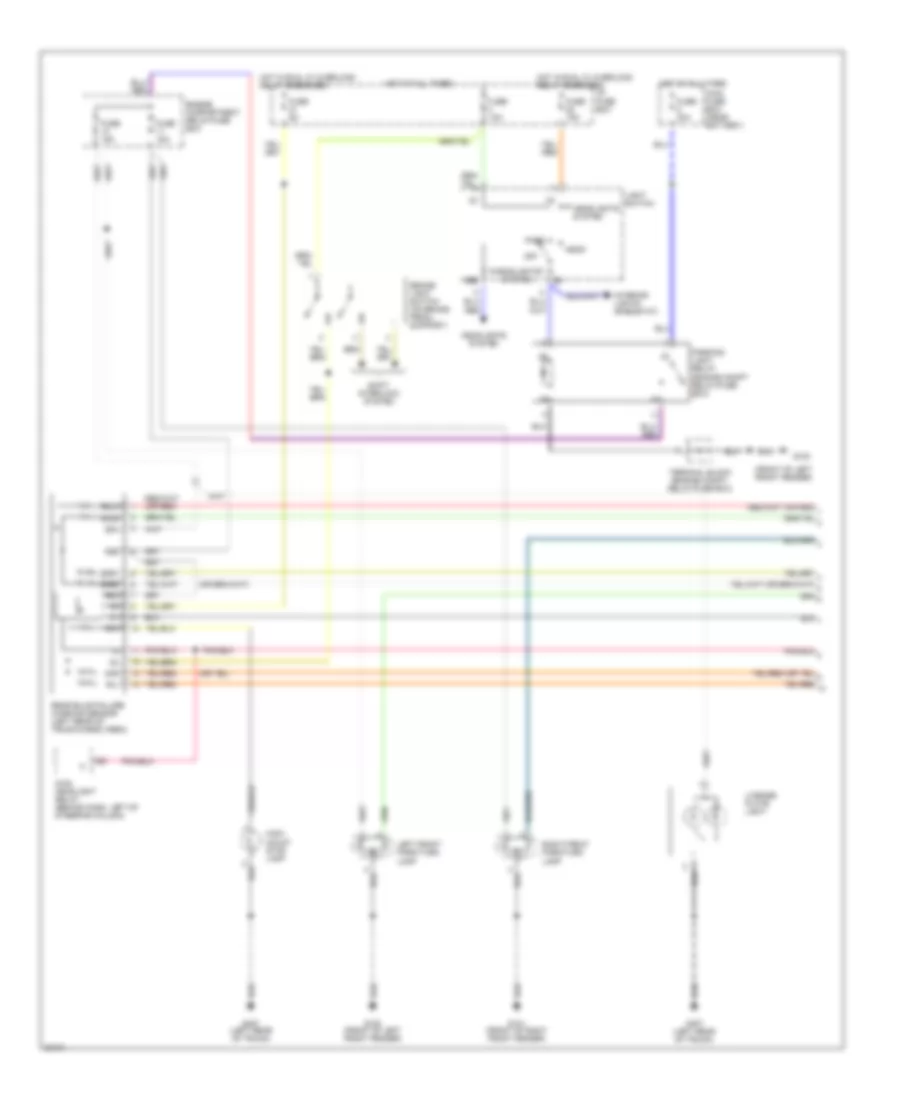
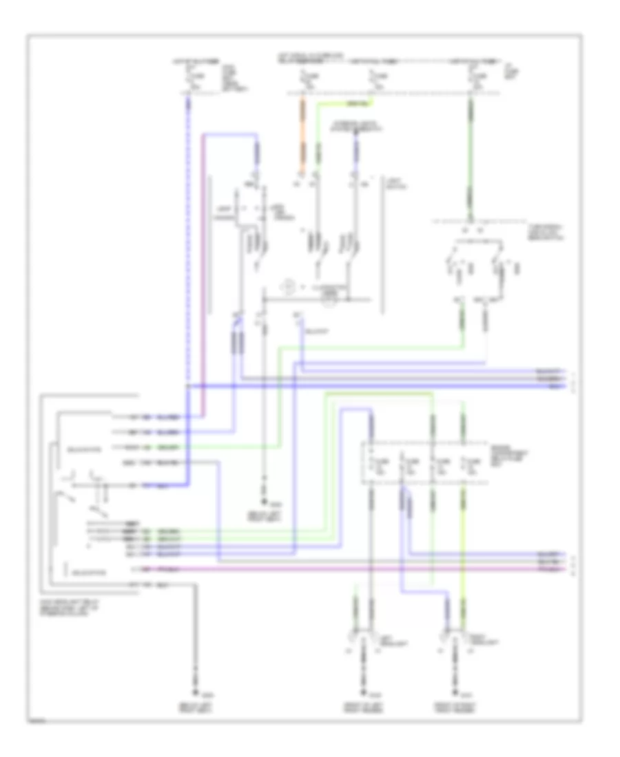
HEADLIGHTS
Headlight Wiring Diagram (1 of 2) for Volvo 960 1997
List of elements for Headlight Wiring Diagram (1 of 2) for Volvo 960 1997:
- (below left front seat)
- (front of left front fender)
- (front of right front fender)
- 15i
- 56a
- 56b
- 56bl
- 56br
- 56bs
- 81a
- Canada
- Engine compartment relay/fuse box
- Exc usa/ canada
- Flash
- Fuse 15a
- Fuse 20a
- Fuse 50a
- G100
- G101
- G300
- Head
- High
- Hot at all times
- Hot in run, w/ overload relay energized
- I/p fuse box
- Illumination lamps
- Interior lights
- Left headlight
- Light switch
- Main fuse box (near battery)
- Main headlight relay (behind dash, left of steering column)
- Off
- Park
- Right headlight
- Solid state
- System (rheostat)
- Turn signal/ high & low beam switch
- Usa
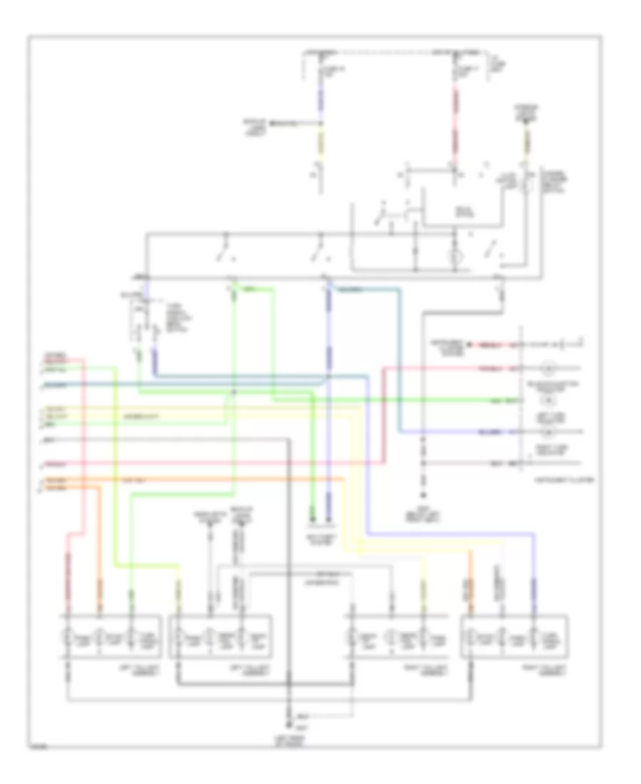
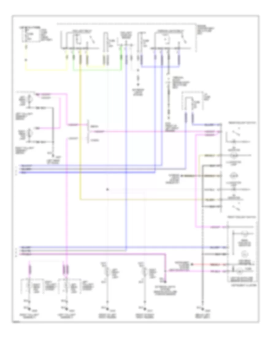
Headlight Wiring Diagram (2 of 2) for Volvo 960 1997
List of elements for Headlight Wiring Diagram (2 of 2) for Volvo 960 1997:
- (below left front seat)
- (front of left front fender)
- (front of right front fender)
- (left rear of trunk)
- (left taillight assembly)
- (right taillight assembly)
- Engine compartment relay/fuse box
- Exterior lights system
- Exterior lights system (rear bulb failure warning sensor)
- Fog light coupling bridge
- Fog light relay
- Front foglight switch
- Fuse
- Fuse 15a
- Fuse 25a
- Fuse 50a
- Fuse 5a
- G100
- G100 (front of left front fender)
- G101
- G300
- G404
- G405
- G407
- High beam indicator
- Hot at all times
- I/p fuse box
- Illumination lamp
- Instrument cluster
- Instrument cluster system (ignition switch)
- Interior lights system (rheostat)
- Left front fog light
- Left rear fog lamp
- Left taillight assembly (sedan)
- Left taillight assembly (wagon)
- Light bulb failure sensor indicator
- Main fuse box (near battery)
- On indicator
- Parking lights relay
- Rear foglight switch
- Rear foglights indicator
- Right front fog light
- Right rear fog lamp
- Right taillight assembly (sedan)
- Right taillight assembly (wagon)
- Sedan
- Terminal block (engine compt relay/fuse box)
- Wagon
HORN
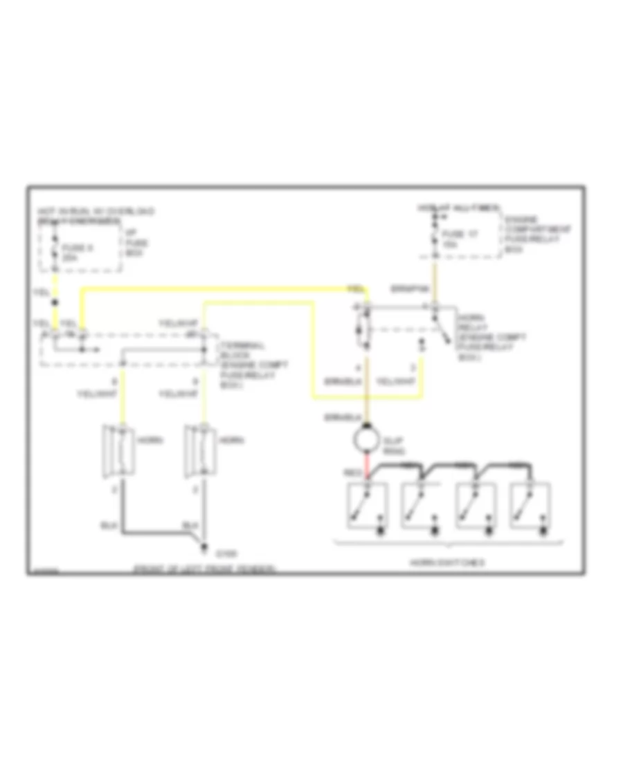
Horn Wiring Diagram for Volvo 960 1997
List of elements for Horn Wiring Diagram for Volvo 960 1997:
- (front of left front fender)
- Engine compartment fuse/relay box
- Fuse 17 15a
- Fuse 6 25a
- G100
- Horn
- Horn relay (engine compt fuse/relay box)
- Horn switches
- Hot at all times
- Hot in run, w/ overload relay energized
- I/p fuse box
- Nca
- Red
- Slip ring
- Terminal block (engine compt fuse/relay box)
INSTRUMENT CLUSTER
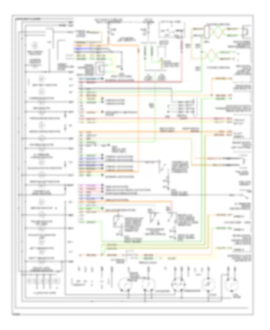
Instrument Cluster Wiring Diagram for Volvo 960 1997
List of elements for Instrument Cluster Wiring Diagram for Volvo 960 1997:
- (+)
- (-)
- (at parking brake)
- (below right front seat)
- (front of left front fender) g100
- (near parking brake)
- (twisted wire pair)
- (w/o amplifier)
- 15a
- A10
- A11
- A12
- A13
- A14
- Abs control module (under left side of dash)
- Abs indicator
- Acc
- Ambient temperature gauge
- Ambient temperature sensor (behind front bumper)
- Anti-lock brakes system
- Aw30-40/30 automatic transmission control module (behind center of i/p)
- B10
- B11
- B12
- B13
- B14
- B18
- B21
- B23
- Brake fluid level sensor (top of brake master cylinder reservoir)
- Brake warning indicator
- Bulb malfunction indicator
- C10
- C11
- C12
- Charging indicator
- Clock
- Coolant level warning indicator
- Cruise control module (center console relay block)
- Ect out
- Electronic climate control module (center of i/p)
- Engine control module (left kick panel)
- Engine coolant level sensor (right side of engine compt in overflow reservoir)
- Engine coolant temperature gauge
- Exterior lights system
- Fuel gauge
- Fuel level sensor
- Fuel pump assembly
- Fuse
- Fuse 10a
- Fuse 15a
- G100 (front of left front fender)
- G101 (front of right front fender)
- G203 (right kick panel)
- G300 (below left front seat)
- G301
- Glove compartment light switch
- Headlights & exterior lights system
- Headlights system
- Hic
- High beam indicator
- Hot at all times
- Hot in run w/ overload relay (x+) energized
- I/p fuse box (left side of i/p)
- Ignition switch
- Illumination lamps
- Instrument cluster
- Interior lights system
- Left turn indicator
- Lvl
- Malfunction indicator lamp
- Mil out
- Nca
- Off
- Oil pressure
- Oil pressure sensor (center console)
- Overdrive indicator
- Parking brake indicator
- Parking brake switch (center console)
- Radio
- Rear fog lamp indicator
- Red
- Rheostat
- Right turn indicator
- Run
- Seal
- Seat belt indicator
- Service indicator
- Speed in
- Speedometer
- Srs warning indicator
- Start
- Starting/charging system
- Tach out
- Tachometer
- Terminal block
- Trailer indicator (not used)
- Transmission mode selector
- Vehicle speed/ abs sensor (rear differential)
- W/ guard alarm ii
- W/o guard alarm ii
- Warning indicator
- Warning system
- Washer fluid level indicator
- Washer fluid level sensor (left front of engine compt in reservoir)
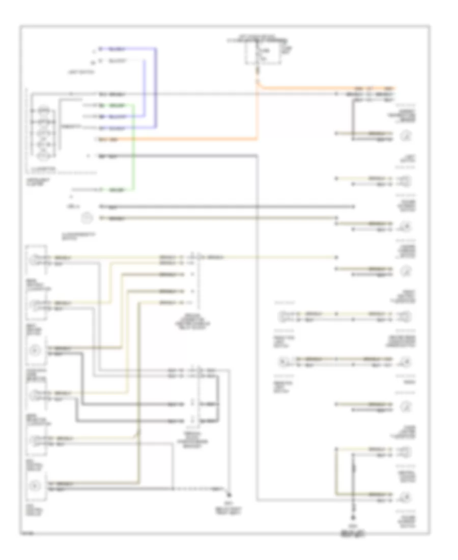
INTERIOR LIGHTS
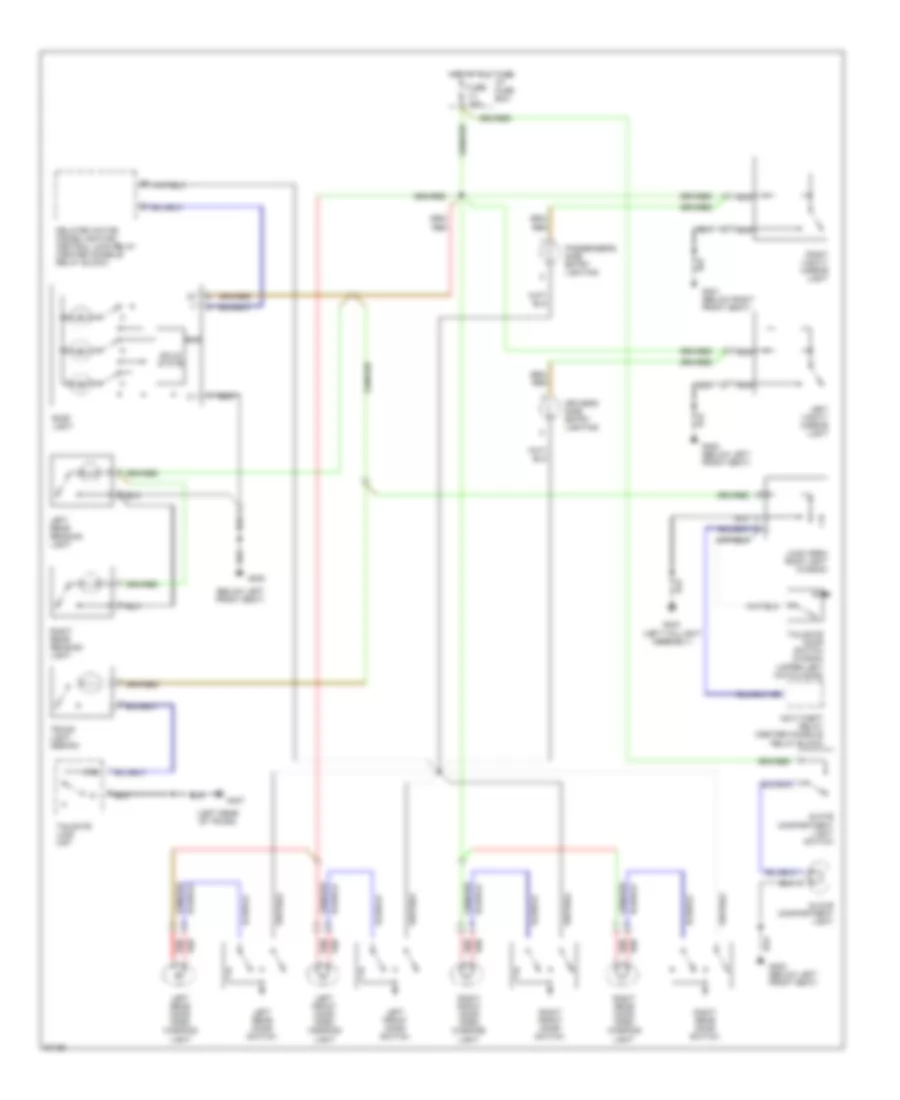
Courtesy Lamps Wiring Diagram for Volvo 960 1997
List of elements for Courtesy Lamps Wiring Diagram for Volvo 960 1997:
- (below left front seat)
- (left rear of trunk)
- (upper left hatch door)
- 31b
- Anti-theft relay (center console relay block)
- Delayed action inside lighting/ central lock relay (center console relay block)
- Driver's side entry lighting
- Fuse 10a
- G300
- G300 (below left front seat)
- G301 (below right front seat)
- G404 (left taillight assembly)
- G407
- Glove compartment light
- Glove compartment light switch
- Hot at all times
- I/p fuse box
- Left front door open warning light
- Left front door switch
- Left rear door open warning light
- Left rear door switch
- Left rear reading light
- Left vanity mirror light
- Load area roof light (wagon)
- Nca
- Passenger's side entry lighting
- Red
- Right front door open warning light
- Right front door switch
- Right rear door open warning light
- Right rear door switch
- Right rear reading light
- Right vanity mirror light
- Roof light
- Solid state
- Tailgate door switch (wagon)
- Tailgate lock unit
- Trunk light (sedan)
Instrument Illumination Wiring Diagram for Volvo 960 1997
List of elements for Instrument Illumination Wiring Diagram for Volvo 960 1997:
- (below left front seat)
- (below right front seat)
- A10
- A11
- Ambient temperature sensor
- Aw30-40/43 mode selector
- B11
- B12
- B13
- Central locking switch
- Cigar lighter illumination
- Clock/rheostat switch
- Ecc control module
- Front ashtray illumination
- Front fog light switch
- Fuse 15a
- G300
- G301
- Gear selector illumination
- Ground connection (center console relay block)
- Hazard warning switch
- Heated rear window/door mirror switch
- Hot in run or acc, w/ overload relay energized
- I/p fuse box
- Illumination
- Instrument cluster
- Light switch
- Mcc control module
- Power antenna switch
- Power sunroof switch
- Radio
- Rear ashtray illumination
- Rear fog light switch
- Rheostat
- Seat heater switch
- Terminal block (parking brake bracket)
MEMORY SYSTEMS
Memory Seat Wiring Diagram for Volvo 960 1997
List of elements for Memory Seat Wiring Diagram for Volvo 960 1997:
- & 1997 only
- (below left front seat) g304
- Back
- Backrest switch
- C10
- C11
- C12
- C13
- C14
- Circuit breaker 30a
- Computer data lines system (diagnostic connector)
- D10
- D11
- D12
- D13
- D14
- D15
- D16
- Down
- Forw
- Forw-backw switch
- Front edge switch
- Fuse 15a
- Hot at all times
- Hot in acc or run, w/ overload relay energized
- I/p fuse box
- Left front seat backrest motor
- Left front seat forward-backward motor
- Left front seat front edge up-down motor
- Left front seat rear edge up-down motor
- Left seat control module (under left front seat)
- Left seat memory switch (on left side of seat)
- M1+
- M1-
- M2+
- M2-
- M3+
- M3-
- M4+
- M4-
- Mem
- Only
- R1+
- R1-
- R2+
- R2-
- R3+
- R3-
- R31
- R4+
- R4-
- Rear edge switch
- Red
- Vg1
- Vg2
- Vg3/4
- Vr1
- Vr2
- Vr3
- Vr4
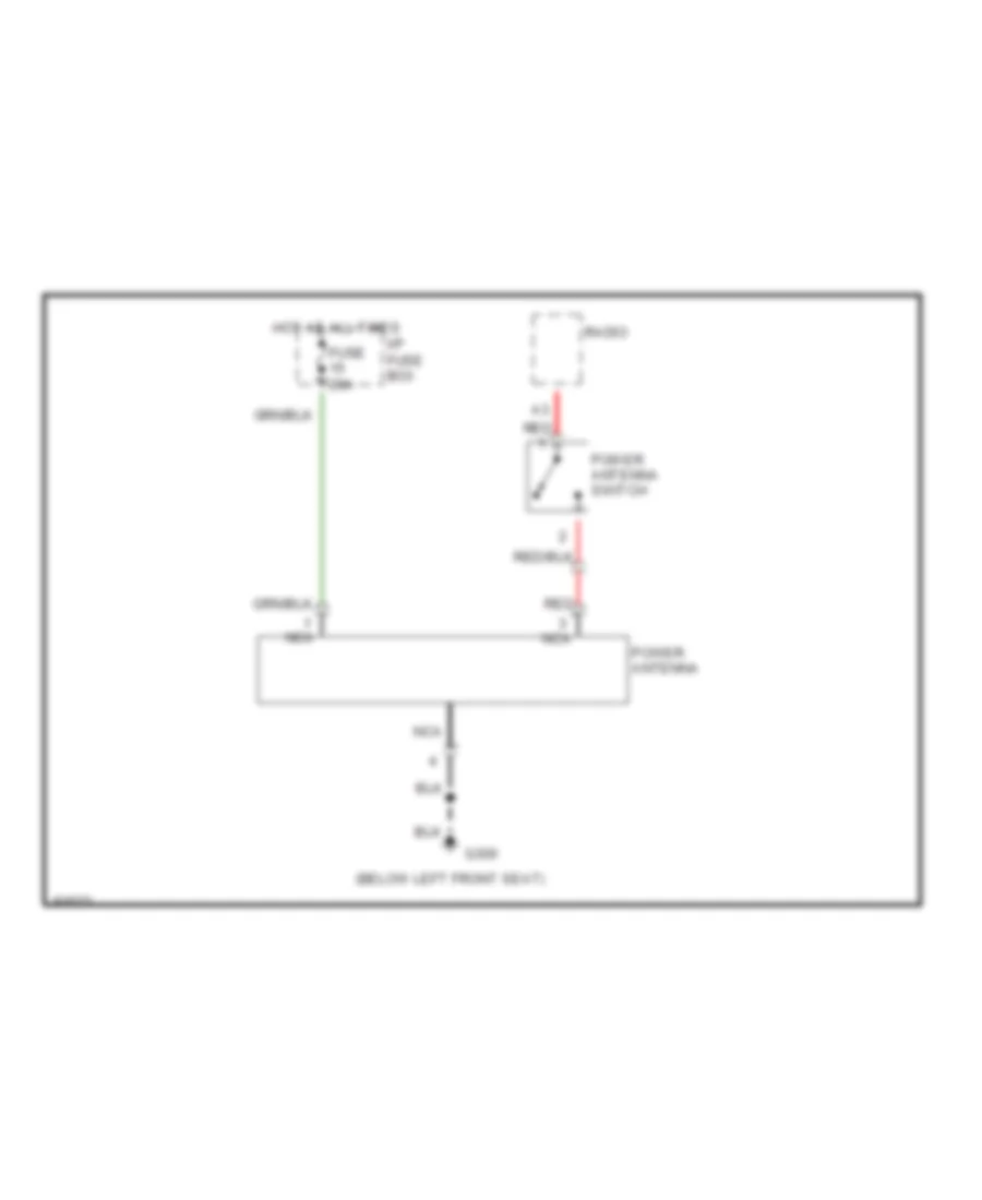
POWER ANTENNA
Power Antenna Wiring Diagram for Volvo 960 1997
List of elements for Power Antenna Wiring Diagram for Volvo 960 1997:
- (below left front seat)
- Fuse 20a
- G300
- Hot at all times
- I/p fuse box
- Nca
- Power antenna
- Power antenna switch
- Radio
- Red
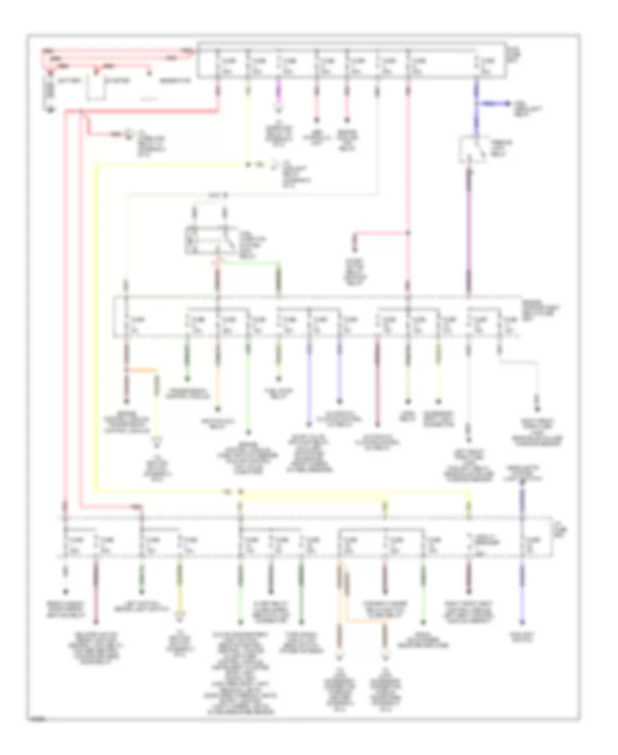
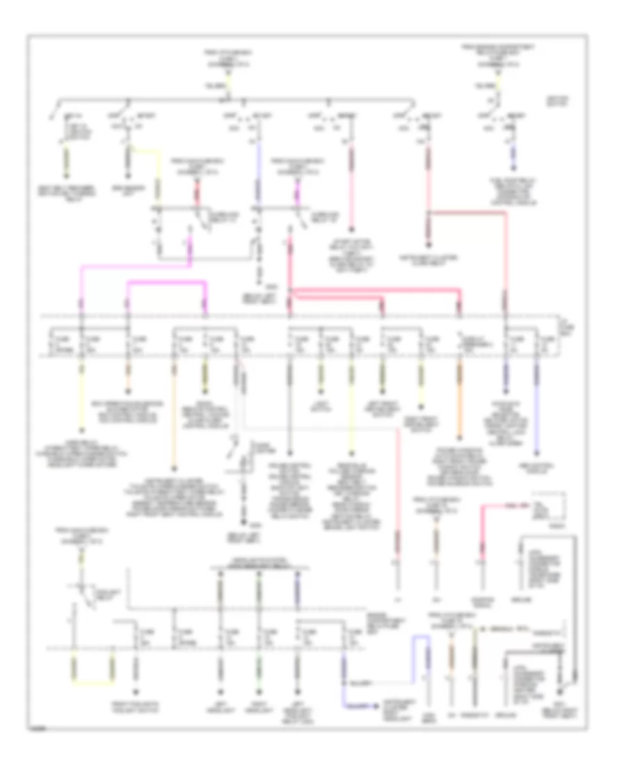
POWER DISTRIBUTION
Power Distribution Wiring Diagram (1 of 2) for Volvo 960 1997
List of elements for Power Distribution Wiring Diagram (1 of 2) for Volvo 960 1997:
- Abs hydraulic unit
- Accessory spot light connector
- Alarm relay, alarm siren, obd data link connector
- Automatic climate control a/c relay
- Battery
- Circuit breaker 30a
- Delayed action inside lighting/ central lock relay, 2-stage central locking driver's door relay
- Engine compartment relay/fuse box
- Engine control module, mass air flow sensor, idle air control (iac) valve, injectors
- Engine control module, transmission control module
- Engine cooling fan relay
- Evap valve, air pump relay, auxiliary air system solenoids, front & rear oxygen sensors
- Foglight switch
- Fuel injection system main relay
- Fuel pump relay
- Fuse 10a
- Fuse 15a
- Fuse 20a
- Fuse 25a
- Fuse 50a
- Fuse 5a
- Fuse n/a
- Generator
- Glove compartment light switch, remote control central locking & car alarm control module, instrument cluster, roof light, trunk light, load area roof light, reading lights, door open warning lights, entry lighting, vanity mirror lights, glass breakage sensor
- Hazard flasher relay/switch, alarm relay
- Headlights system (light switch)
- Horn relay
- I/p fuse box
- Ignition coil relay
- Left front park/turn lamp, foglight relay, rear bulb failure warning sensor
- Light switch, brake light switch
- Main fuse box
- Main headlight relay
- Parking light relay
- Pnk
- Radio, cd-changer, booster amplifier
- Rear window/ door mirror heating relay
- Red
- Right front park/turn lamp, rear bulb failure warning sensor
- Right front seat control module, left seat control module (memory)
- Start motor relay, air pump relay
- Starter
- To 4-pin accessory connector (mobile telephone) (diagram 2 of 2)
- To 4-pin accessory connector (parking heater) (diagram 2 of 2)
- To foglight relay (diagram 2 of 2)
- To ignition switch (diagram 2 of 2)
- To overload relay +x (diagram 2 of 2)
- To overload relay 15i (diagram 2 of 2)
- Transmission control module
- Turn signal high & low beam switch, power antenna
Power Distribution Wiring Diagram (2 of 2) for Volvo 960 1997
List of elements for Power Distribution Wiring Diagram (2 of 2) for Volvo 960 1997:
- (below left front seat)
- 15a
- 15i
- 30+
- 30i
- 4-pin accessory connector (mobile telephone) (right side of i/p)
- 4-pin accessory connector (parking heater) (right side of i/p)
- Abs control module
- Acc
- Aw30-40/43 mode selector, delayed action inside lighting/ central lock relay, alarm siren
- B12
- Cigar lighter
- Circuit breaker 2 30a
- Cruise control switch, cruise control module, back-up light switch, transmission range sensor, hazard flasher relay/switch
- Damping signal
- Ecc operating solenoids, blower motor, ecc control module, mcc control module
- Engine compartment relay/fuse box
- Foglight relay
- From engine compartment relay/fuse box fuse 1 (diagram 1 of 2)
- From i/p fuse box fuse 16 (diagram 1 of 2)
- From i/p fuse box fuse 4 (diagram 1 of 2)
- From main fuse box fuse 1 (diagram 1 of 2)
- From main fuse box fuse 2 (diagram 1 of 2)
- From main fuse box fuse 3 (diagram 1 of 2)
- Front foglights, foglight switch
- Fuel pump relay, obd data link connector, motronic mfi control module
- Fuse 15a
- Fuse 20a
- Fuse 25a
- Fuse 5a
- Fuse spare
- G300
- G301 (below right front seat)
- Ground
- Headlights system (main headlight relay)
- High beam
- Horn relay, intermittent wiper relay, winshield wiper/washer switch, windshield wiper motor, headlight wiper motors
- I/p fuse box
- Ignition switch
- Instrument cluster
- Instrument cluster, alarm relay
- Instrument cluster, right headlight
- Instrument cluster, tailgate wiper/washer switch, tailgate intermittent wiper relay, tailgate wiper motor, ambient temperature sensor, power door mirror switches, right front seat control module
- Key in ignition switch
- Key-in
- Left front heated seat switch
- Left headlight
- Left headlight, foglight relay (usa)
- Light switch
- Off
- Overload relay +x
- Overload relay 15i
- Pnk
- Power windows auto down relay, right front power window switch, driver's door power window switch, power sunroof switch
- Radio
- Radio, remote control central locking & car alarm control module
- Rear bulb failure warning sensor, seat belt reminder/ignition key warning relay, rear window/ door mirror heating relay, instrument cluster, brake light switch
- Red
- Relay
- Rheostat
- Right front heated seat switch
- Right headlight
- Seat belt reminder/ ignition key warning
- Srs sensor unit
- Start
- Start motor relay (w/o anti- theft), service socket, alarm relay (w/ anti-theft)
- Tel mute input
POWER DOOR LOCKS
Central Locking Wiring Diagram for Volvo 960 1997
List of elements for Central Locking Wiring Diagram for Volvo 960 1997:
- (below left front seat) g300
- (center console relay block) delayed action inside lighting/ central lock relay
- (rear of left front door) driver's door lock module
- (rear of right front door) passenger's door lock module
- 2-stage central locking driver's door relay (center console relay block)
- Anti-theft relay (console relay block)
- Central locking switch
- Fuse 20a
- Fuse 5a
- G301 (below right front seat)
- G404 (left rear of trunk)
- Hot at all times
- Hot in run or start
- I/p fuse box
- Interior lights system
- Left front door switch
- Left rear door central locking motor
- Left rear door switch
- Lock
- Nca
- Remote controlled central locking relay (console relay block)
- Right front door switch
- Right rear door central locking motor
- Right rear door switch
- Sedan
- Tailgate central locking motor
- Tailgate lock unit
- Terminal block (parking brake bracket)
- Unlock
- W/ anti- theft
- W/ remote central locking
- Wagon
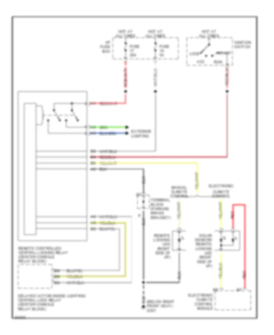
Remote/Central Locking Wiring Diagram for Volvo 960 1997
List of elements for Remote/Central Locking Wiring Diagram for Volvo 960 1997:
- (below right front seat) g301
- Acc
- Climate control
- Delayed action inside lighting/ central lock relay (center console relay block)
- Electronic
- Electronic climate control module
- Exterior lighting
- Fuse 20a
- Fuse 5a
- Hot at all times
- I/p fuse box
- Ignition switch
- Lock
- Manual climate control
- Red
- Remote controlled central locking relay (center console relay block)
- Remote locking led (right side of i/p)
- Run
- Solar sensor/ remote locking led (right side of i/p)
- Start
- Terminal block (parking brake bracket)
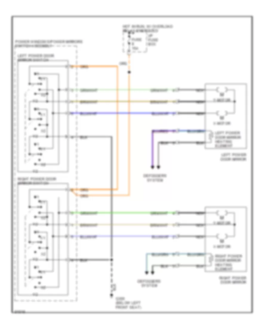
POWER MIRRORS
Power Mirror Wiring Diagram for Volvo 960 1997
List of elements for Power Mirror Wiring Diagram for Volvo 960 1997:
- Defoggers system
- Fuse 15a
- G300 (below left front seat)
- Hot in run, w/ overload relay energized
- I/p fuse box
- Left power door mirror
- Left power door mirror heating element
- Left power door mirror switch
- Nca
- Power windows/power mirrors switch assembly
- Right power door mirror
- Right power door mirror heating element
- Right power door mirror switch
- X-motor
- Y-motor
POWER SEATS
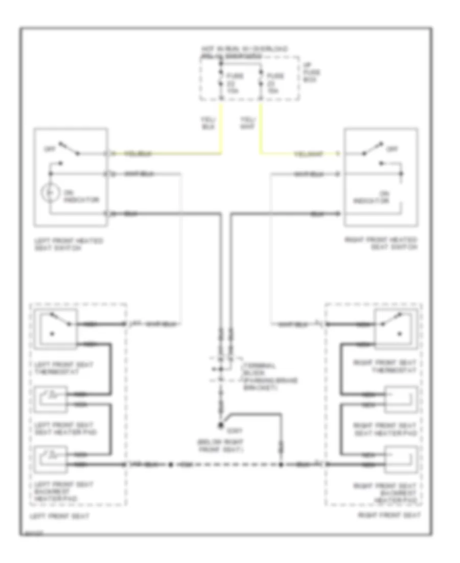
Heated Seats Wiring Diagram for Volvo 960 1997
List of elements for Heated Seats Wiring Diagram for Volvo 960 1997:
- (below right front seat)
- Fuse 15a
- G301
- Hot in run, w/ overload relay energized
- I/p fuse box
- Left front heated seat switch
- Left front seat
- Left front seat thermostat
- Left front seat backrest heater pad
- Left front seat seat heater pad
- Nca
- Off
- On indicator
- Right front heated seat switch
- Right front seat
- Right front seat backrest heater pad
- Right front seat seat heater pad
- Right front seat thermostat
- Terminal block (parking brake bracket)
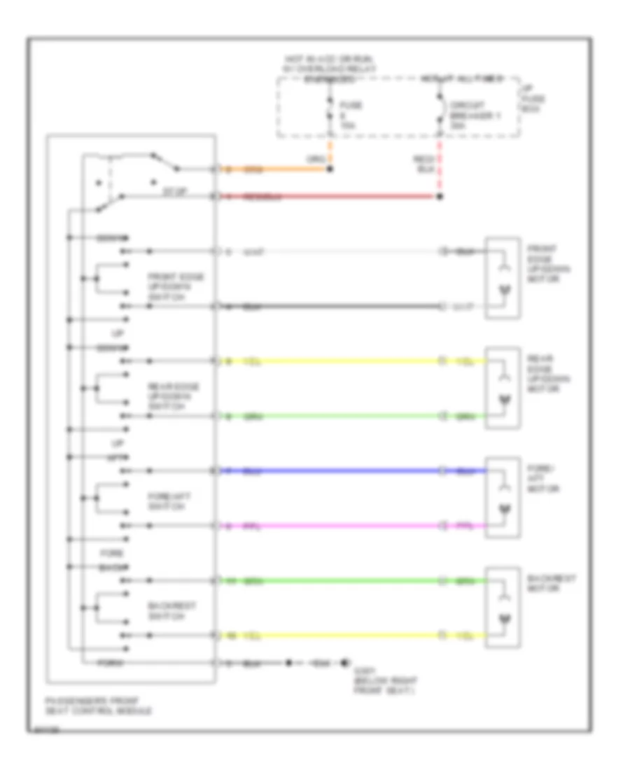
Passenger's Power Seat Wiring Diagram for Volvo 960 1997
List of elements for Passenger's Power Seat Wiring Diagram for Volvo 960 1997:
- Aft
- Back
- Backrest motor
- Backrest switch
- Circuit breaker 1 30a
- Down
- Fore
- Fore/ aft motor
- Fore/aft switch
- Forw
- Front edge up/down motor
- Front edge up/down switch
- Fuse 15a
- G301 (below right front seat)
- Hot at all times
- Hot in acc or run, w/ overload relay energized
- I/p fuse box
- Passenger's front seat control module
- Rear edge up/down motor
- Rear edge up/down switch
- Stop
POWER TOP/SUNROOF
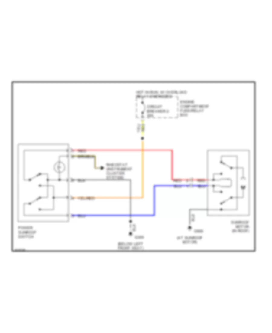
Power Top/Sunroof Wiring Diagrams for Volvo 960 1997
List of elements for Power Top/Sunroof Wiring Diagrams for Volvo 960 1997:
- (at sunroof motor)
- (below left front seat)
- Circuit breaker 2 30a
- Engine compartment fuse/relay box
- G300
- G908
- Hot in run, w/ overload relay energized
- Power sunroof switch
- Red
- Rheostat (instrument cluster system)
- Sunroof motor (in roof)
POWER WINDOWS
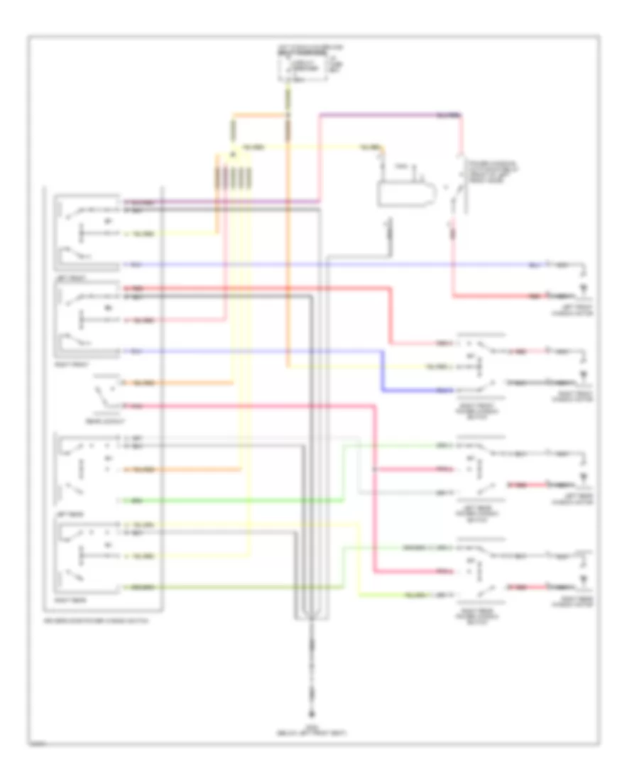
Power Window Wiring Diagram for Volvo 960 1997
List of elements for Power Window Wiring Diagram for Volvo 960 1997:
- Circuit breaker 30a
- Driver's door power window switch
- G300 (below left front seat)
- Hot in run w/overload relay energized
- I/p fuse box
- Left front
- Left front window motor
- Left rear
- Left rear power window switch
- Left rear window motor
- Nca
- Pnk
- Power windows auto down relay (front of left front door)
- Rear lockout
- Red
- Right front
- Right front power window switch
- Right front window motor
- Right rear
- Right rear power window switch
- Right rear window motor
RADIO
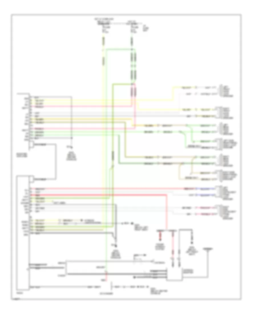
Radio Wiring Diagrams, with Amplifier for Volvo 960 1997
List of elements for Radio Wiring Diagrams, with Amplifier for Volvo 960 1997:
- (not used)
- +acc
- +ant
- +batt
- Antenna
- Antenna booster
- Booster/ amplifier
- Cd changer
- Dimmer
- Din
- Din cable
- Dl+
- Dl-
- Dr+
- Dr-
- Fuse 10a
- Fuse 15a
- G300 (below left front seat)
- G302 (below center console)
- Gnd
- Hot at all times
- Hot w/ overload relay 1 (x+) energized
- I/p fuse box
- Interior lights system
- Left front door loud- speaker
- Left rear door loud- speaker
- Left side instrument panel loud- speaker
- Left side rear parcel shelf loud- speaker
- Lf+
- Lf-
- Lr+
- Lr-
- Nca
- Power antenna system
- Radio
- Red
- Rf+
- Rf-
- Rheo+
- Rheo-
- Right front door loud- speaker
- Right rear door loud- speaker
- Right side instrument panel loud- speaker
- Right side rear parcel shelf loud- speaker
- Rr+
- Rr-
- Sedan
- Sedan only
- Wagon
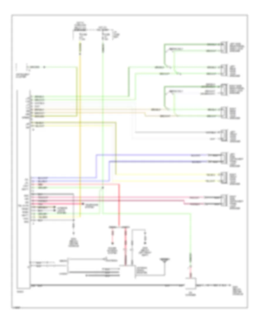
Radio Wiring Diagrams, without Amplifier for Volvo 960 1997
List of elements for Radio Wiring Diagrams, without Amplifier for Volvo 960 1997:
- +acc
- +ant
- +batt
- +dl
- +dr
- +lf
- +lr
- +rf
- +rheo
- +rr
- -dr
- -rheo
- -rr
- Antenna
- Antenna signal booster
- Cd changer
- Din
- Fuse 15a
- G300 (below left front seat)
- G302 (below center console)
- Gnd
- Hot at all times
- Hot w/ overload relay (+x) energized
- I/p fuse box
- Instrument cluster
- Interior lights system
- Left front door loud- speaker
- Left rear door loud- speaker
- Left side instrument panel loud- speaker
- Left side rear parcel shelf loud- speaker
- Nca
- Pnk
- Power antenna system
- Radio
- Red
- Right front door loud- speaker
- Right rear door loud- speaker
- Right side instrument panel loud- speaker
- Right side rear parcel shelf loud- speaker
- Sedan
- Sedan only
- Speed
- Tel mute
- Telephone system
- Wagon
- _dl
- _lf
- _lr
- _rf
SHIFT INTERLOCKS
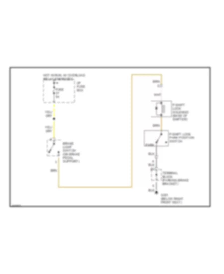
Shift Interlock Wiring Diagram for Volvo 960 1997
List of elements for Shift Interlock Wiring Diagram for Volvo 960 1997:
- Brake light switch (on brake pedal support)
- Fuse 5a
- G301 (below right front seat)
- Hot in run, w/ overload relay energized
- I/p fuse box
- P-shift lock park position switch
- P-shift lock solenoid (base of shifter)
- Park
- Terminal block (parking brake bracket)
STARTING/CHARGING
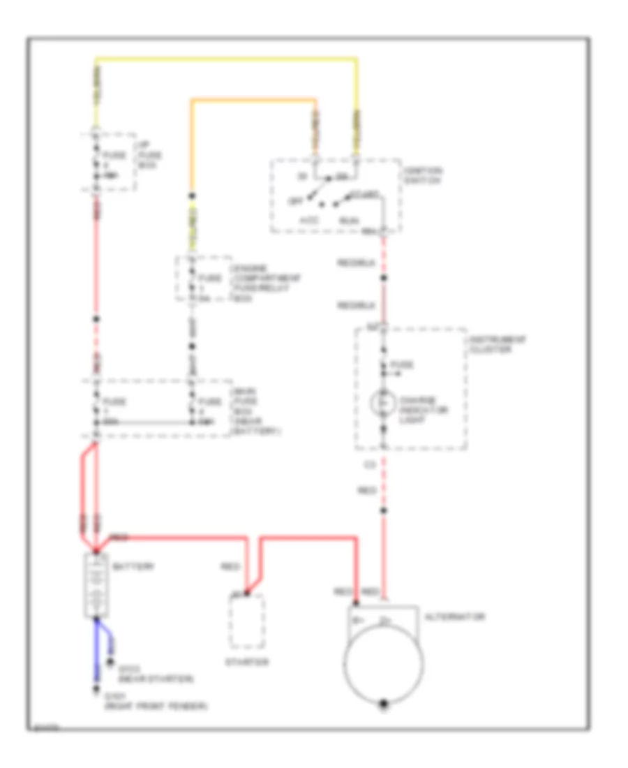
Charging Wiring Diagram for Volvo 960 1997
List of elements for Charging Wiring Diagram for Volvo 960 1997:
- 15a
- 30i
- Acc
- Alternator
- Battery
- Charge indicator light
- Engine compartment fuse/relay box
- Fuse
- Fuse 10a
- Fuse 50a
- Fuse 5a
- G101 (right front fender)
- G133 (near starter)
- I/p fuse box
- Ignition switch
- Instrument cluster
- Main fuse box (near battery)
- Off
- Red
- Run
- Start
- Starter
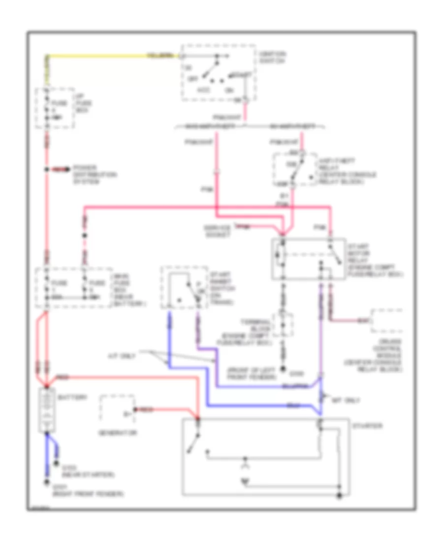
Starting Wiring Diagram for Volvo 960 1997
List of elements for Starting Wiring Diagram for Volvo 960 1997:
- (front of left front fender)
- 50e
- 50f
- A/t only
- Acc
- Anti-theft relay (center console relay block)
- Battery
- Cruise control module (center console relay block)
- Fuse 10a
- Fuse 50a
- G100
- G101 (right front fender)
- G133 (near starter)
- Generator
- I/p fuse box
- Ignition switch
- M/t only
- Main fuse box (near battery)
- Off
- P or n
- Pnk
- Pnk service socket
- Power distribution system
- Red
- Start
- Start inhibit switch (on trans)
- Start motor relay (engine compt fuse/relay box)
- Starter
- Terminal block (engine compt. fuse/relay box)
- W/ anti-theft
- W/o anti-theft
SUPPLEMENTAL RESTRAINTS
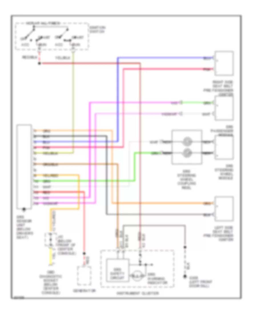
Supplemental Restraint Wiring Diagram for Volvo 960 1997
List of elements for Supplemental Restraint Wiring Diagram for Volvo 960 1997:
- A11
- Acc
- G309 (left front door sill)
- Generator
- Hot at all times
- Ignition switch
- Instrument cluster
- J/c (below front of center console)
- Left side seat belt pre-tensioner igniter
- Nca
- Obd diagnostic socket (below center console)
- Off
- Pnk
- Red
- Right side seat belt pre-tensioner igniter
- Run
- Srs passenger module
- Srs safety circuit
- Srs sensor unit (below driver's seat)
- Srs steering wheel coupling reel
- Srs steering wheel module
- Srs warning indicator
- Start
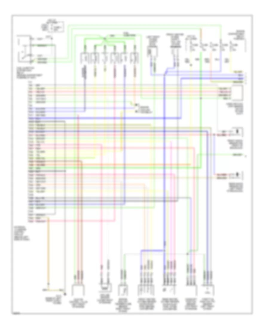
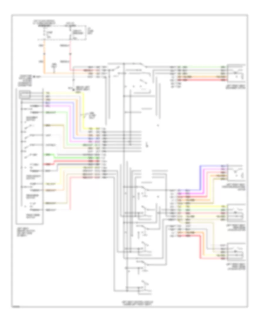
TRANSMISSION
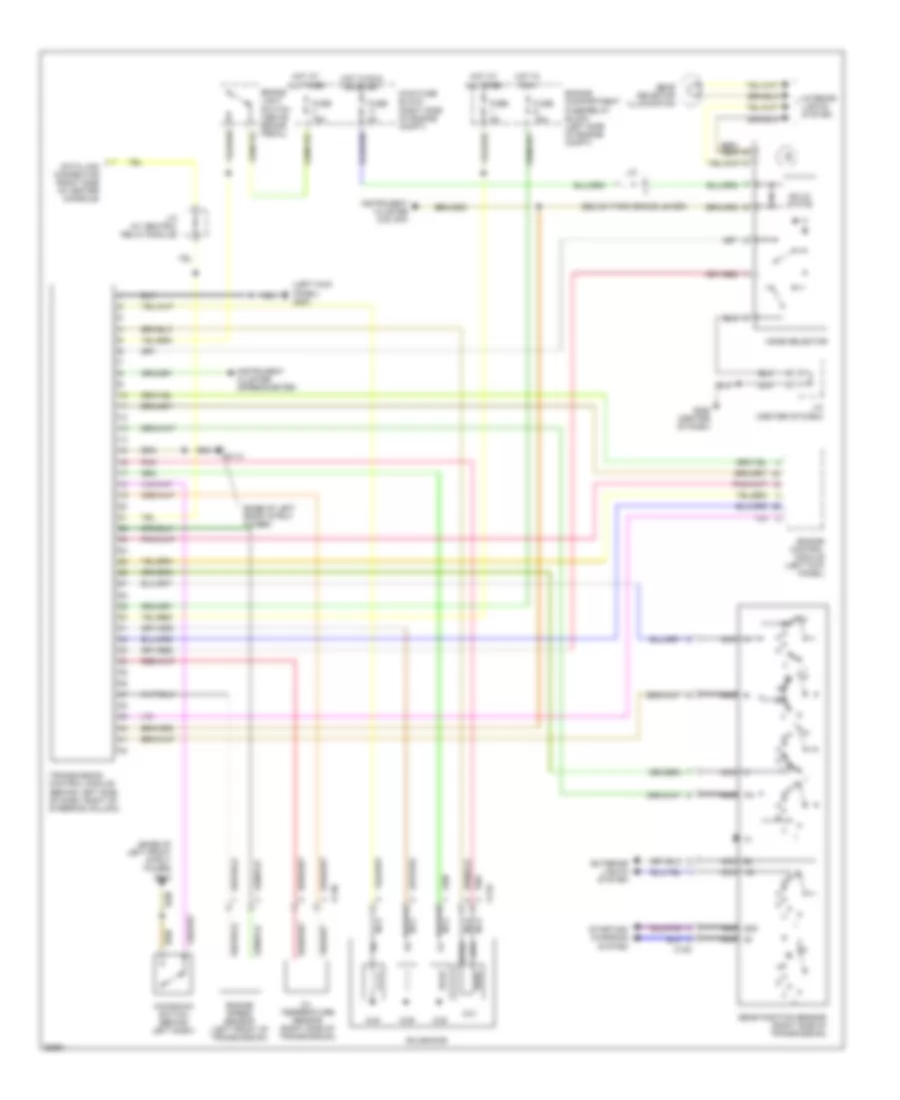
A/T Wiring Diagram for Volvo 960 1997
List of elements for A/T Wiring Diagram for Volvo 960 1997:
- (base of left front strut tower)
- (base of left front strut tower) g113
- (below park brake lever)
- (left kick panel) g200
- 15i nca
- 50s nca
- 8/38
- 8/39
- 8/40
- 8/41
- A nca
- B nca
- Bl nca
- Brake light switch (above brake pedal)
- C nca
- C128
- C129
- C130
- Data link connector (right side of center console)
- Engine compartment fuse/relay block (left side of engine compt)
- Engine control module (left kick panel)
- Engine speed sensor (left front of transmission)
- Exterior lights system
- Fuse 15a
- Fuse 5a
- G113
- G206 (center of dash)
- Gear position sensor (right side of transmission)
- Gear selector illumination
- Hot at all times
- Hot in run
- Hot in run or start
- Instrument cluster (o/d off)
- Instrument cluster (speedometer)
- Interior lights system
- J/c
- J/c (at central relay module)
- J/c (center of dash)
- Kickdown switch (behind left dash)
- Main fuse block (right side of engine compt)
- Mode selector
- Nca
- Oil temperature sensor (right side of transmission)
- Pa nca
- Pnk
- Solenoids
- Solid state
- Starting/ charging system
- Sth
- Sthg
- Transmission control module (behind left side of dash, right of steering column)
WARNING SYSTEMS
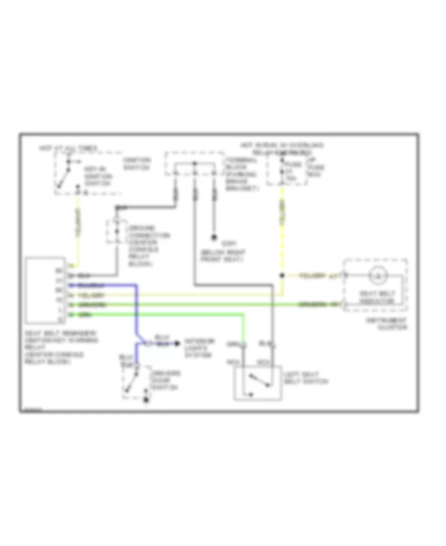
Warning System Wiring Diagrams for Volvo 960 1997
List of elements for Warning System Wiring Diagrams for Volvo 960 1997:
- (below right front seat)
- Driver's door switch
- Fuse 15a
- G301
- Ground connection (center console relay block)
- Hot at all times
- Hot in run, w/ overload relay energized
- I/p fuse box
- Ignition switch
- Instrument cluster
- Interior lights system
- Key-in ignition switch
- Left seat belt switch
- Nca
- Seat belt indicator
- Seat belt reminder/ ignition key warning relay (center console relay block)
- Terminal block (parking brake bracket)
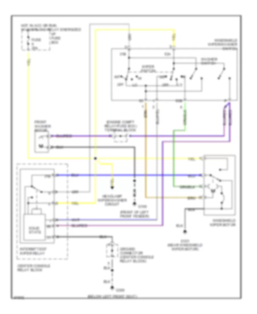
WIPER/WASHER
Front Wiper/Washer Wiring Diagram for Volvo 960 1997
List of elements for Front Wiper/Washer Wiring Diagram for Volvo 960 1997:
- (below left front seat)
- (engine compt relay/fuse box) terminal block
- (front of left front fender)
- 31b
- 53a
- 53b
- Center console relay block
- Front washer motor
- Fuse 25a
- G100
- G121 (near windshield wiper motor)
- G300
- Ground connector (center console relay block)
- Headlamp wiper/washer circuit
- Hot in acc or run, w/ overload relay energized
- I/p fuse box
- Int
- Intermittent wiper relay
- Off
- Solid state
- Washer switch
- Windshield wiper motor
- Windshield wiper/washer switch
- Wiper switch
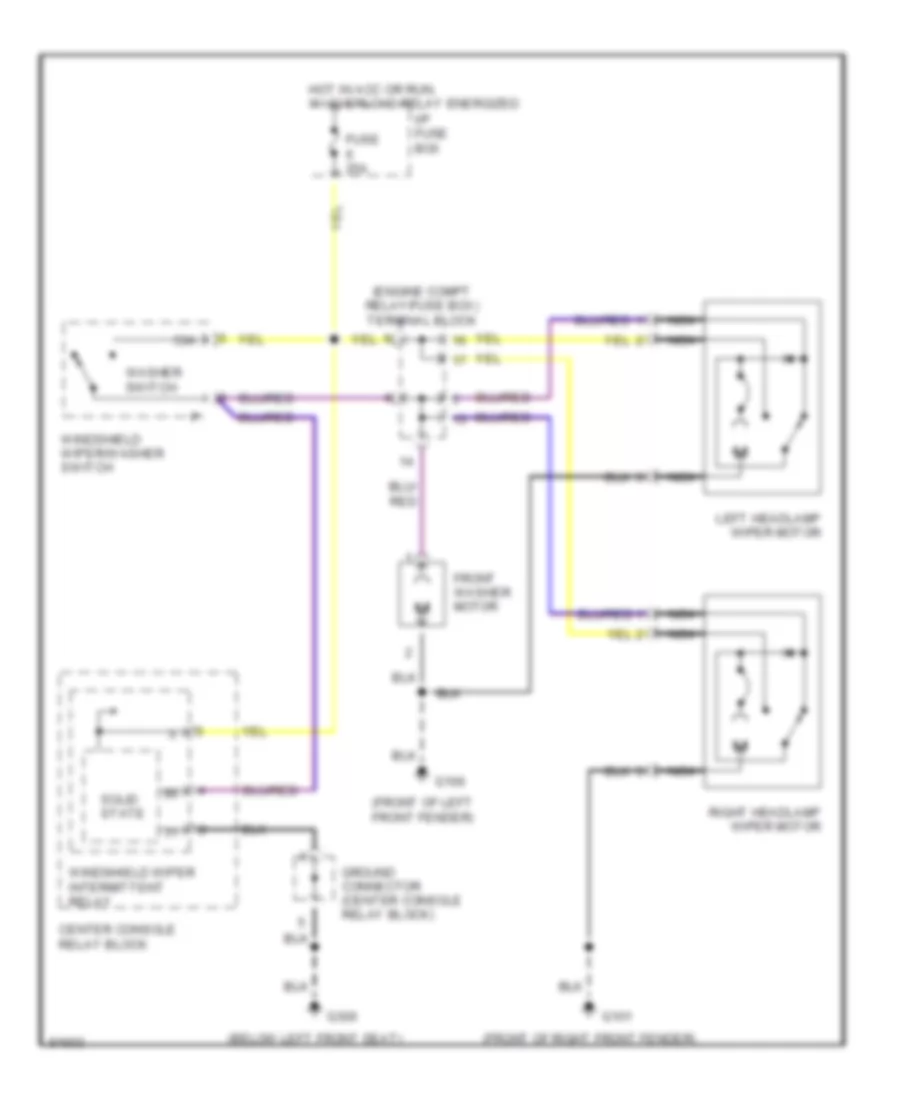
Headlamp Wiper/Washer Wiring Diagram for Volvo 960 1997
List of elements for Headlamp Wiper/Washer Wiring Diagram for Volvo 960 1997:
- (below left front seat)
- (engine compt relay/fuse box) terminal block
- (front of left front fender)
- (front of right front fender)
- 53a
- Center console relay block
- Front washer motor
- Fuse 25a
- G100
- G101
- G300
- Ground connector (center console relay block)
- Hot in acc or run, w/ overload relay energized
- I/p fuse box
- Left headlamp wiper motor
- Nca
- Right headlamp wiper motor
- Solid state
- Washer switch
- Windshield wiper intermittent relay
- Windshield wiper/washer switch
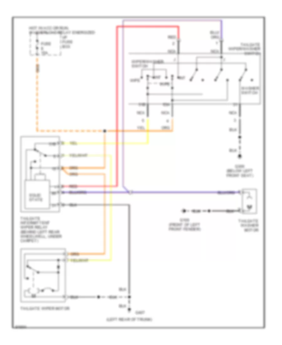
Rear Wiper/Washer Wiring Diagram for Volvo 960 1997
List of elements for Rear Wiper/Washer Wiring Diagram for Volvo 960 1997:
- (left rear of trunk)
- 31b
- 53a
- Fuse 15a
- G100 (front of left front fender)
- G300 (below left front seat)
- G407
- Hot in acc or run, w/ overload relay energized
- I/p fuse box
- Int
- Nca
- Red
- Solid state
- Tailgate intermittent wiper relay (behind left rear wheelwell, under carpet)
- Tailgate washer motor
- Tailgate wiper motor
- Tailgate wiper/washer switch
- Washer switch
- Wipe
- Wiper/washer switch

 Čeština
 Dansk
Dansk Ελληνικά
 English
 English
 Español
 Suomi
Suomi Français
 Français
 עברית
עברית Hrvatski
 Magyar
 Italiano
 日本語
日本語 한국어
한국어 Nederlands
 Polski
 Português
 Português
 Română
 Русский
 Slovenčina
 Slovenščina
 Svenska
 Türkçe
 中文 (中国)