DEFOGGERS
Defoggers Wiring Diagram for Hyundai XG350 L 2004
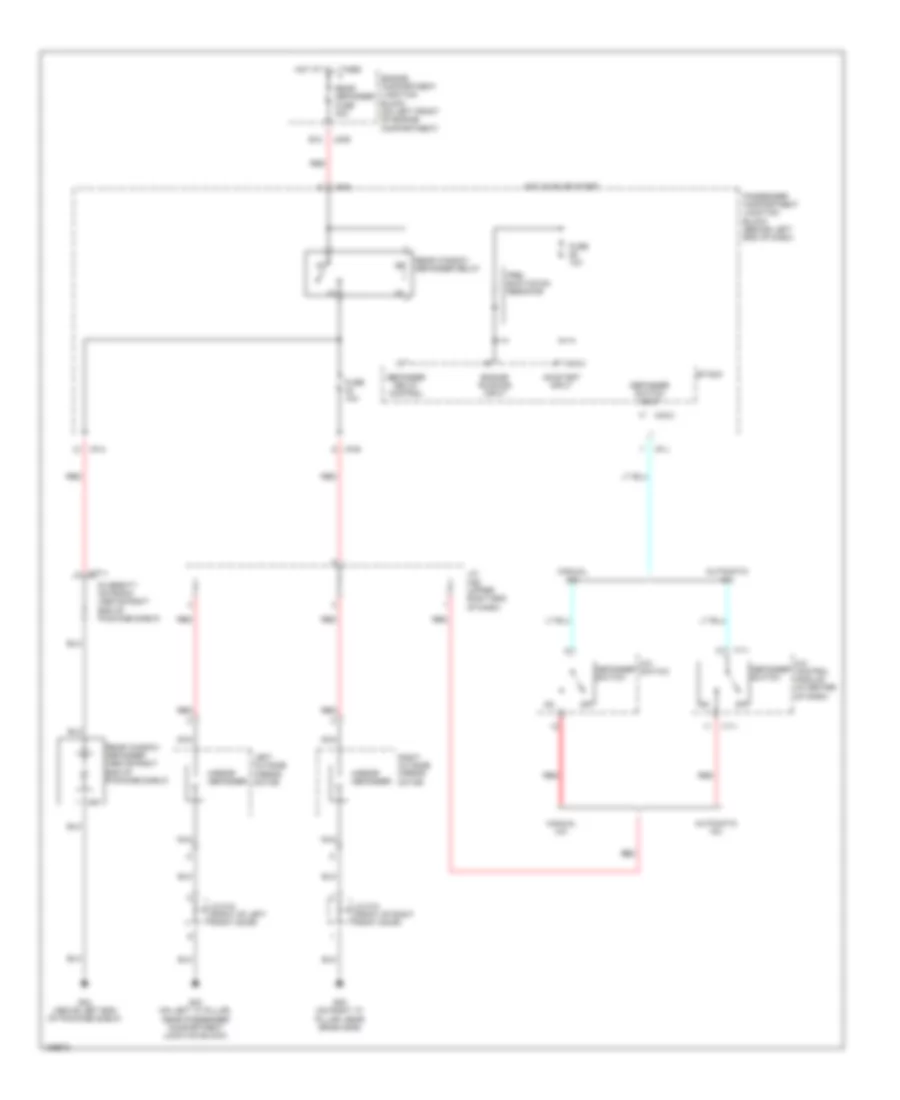
List of elements for Defoggers Wiring Diagram for Hyundai XG350 L 2004:
- A/c control module (in center of dash)
- A/c switch
- Automatic a/c
- B12
- Defogger relay control
- Defogger switch
- Defogger switch input
- Diversity antenna (above right end of package shelf)
- Engine compartment junction block (on left front of engine compartment)
- Engine running input
- Etacm
- Fuse 10a
- G03 (on left "a" pillar, near passenger compartment junction block)
- G05 (on right "a" pillar, near crash bar)
- G24 (above left end of package shelf)
- Hot at all times
- Hot in on or start
- I/p-a
- I/p-b
- I/p-j
- I/p-p
- I17-1
- J/c d12 (front of left front door)
- J/c d13 (front of right front door)
- J/c m36 (upper right end of dash)
- Jm09
- Left outside mirror motor
- M33-3
- M77-1
- M91
- Manual a/c
- Mirror defogger
- Nca
- Off
- On/start input
- Passenger compartment junction block (behind left end of dash)
- Pre- excitation resistor
- Rear defogger fuse 30a
- Rear window defogger (above right end of package shelf)
- Rear window defogger relay
- Red
- Right outside mirror motor
 English