DEFOGGERS
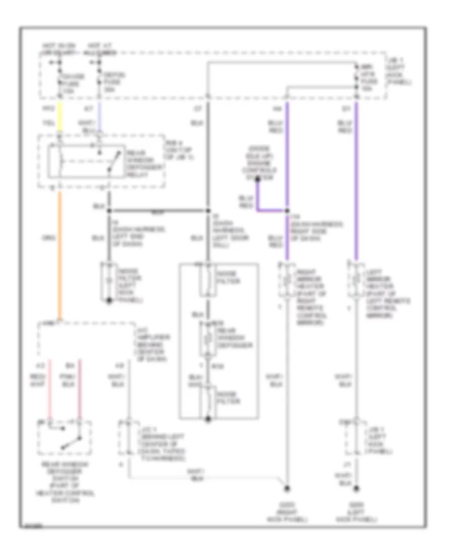
Defogger Wiring Diagram for Toyota Supra 1997
List of elements for Defogger Wiring Diagram for Toyota Supra 1997:
- (diode idle-up) engine controls system
- A/c amplifier (behind center of dash)
- A18
- D10
- Defog fuse 30a
- G200 (left kick panel)
- G203 (right kick panel)
- Gauge fuse 10a
- H12
- Hot at all times
- Hot in on or start
- I14 (dash harness, right side of dash)
- I6 (dash harness, left door sill)
- J/b 1 (left kick panel)
- J/c 1 (behind left center of dash, taped to harness)
- Left mirror heater (part of left remote control mirror)
- Mir- htr fuse 10a
- Noise filter
- Noise filter (left kick panel)
- Of dash)
- R/b 4 (on top of j/b 1)
- R18
- R19
- Rear window defogger
- Rear window defogger switch (part of heater control switch)
- Rear window defogger relay
- Right mirror heater (part of right remote control mirror)
 English