TRANSMISSION
3.0L
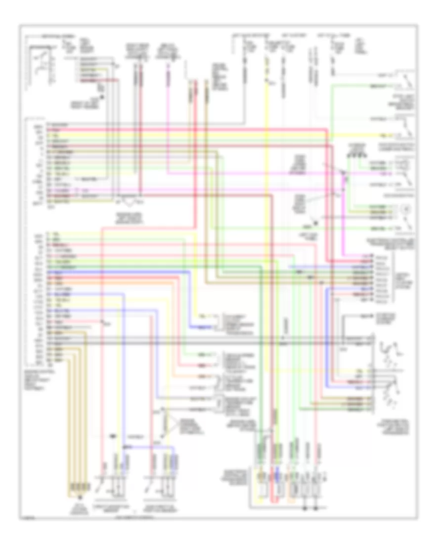
3.0L Non-Turbo, A/T Wiring Diagram for Toyota Supra 1997

List of elements for 3.0L Non-Turbo, A/T Wiring Diagram for Toyota Supra 1997:
- (dash harn, right end of dash) i21
- (dash harn, right side of dash)
- (dash harn, right side of dash) i17
- (engine harn, left rear of engine)
- (engine harn, right side of firewall)
- (engine harn, upper front of engine) e23
- (left kick panel)
- (under gas pedal)
- A/t fluid temperature sensor (on trans)
- B6 (body harn, left quarter panel)
- Batt
- Cruise control ecu (behind left side of dash)
- E10
- E12
- E20
- E25 (engine harness, left side of engine compt)
- E26
- E28
- E28 (engine harn, right side of firewall)
- Efi fuse 30a
- Efi main relay
- Electronic controlled trans- mission pattern select switch
- Electronic controlled transmission solenoid
- Engine control module (below right front footrest)
- Engine coolant temperature sensor (left front of cyl head)
- Eo1
- Eo2
- Eo3
- Exterior lights system
- G100 (front of left front fender)
- G114 (intake manifold)
- G200
- Gauge fuse 10a
- H13
- Hot at all times
- Hot in on or start
- Hot in start
- I10
- I17
- I4 (dash harn, left end of dash)
- Idl1
- Ign fuse 7.5a
- Igsw
- Instrument cluster system
- Interior lights system
- J/b 1 (left kick panel)
- Kick down switch
- M-rel
- Mass air flow sensor (behind air filter housing)
- No. 1
- No. 2
- No. 3
- Nsw
- O/d main switch
- Od1
- Od2
- Oil
- Park/neutral position switch (left side of transmission)
- Pin 6
- Pin c10
- Pin c11
- Pin c12
- Pin c2
- Pin c4
- Pin c6
- Pin c7
- Pin c8
- Pnk
- R/b 2 (left engine compt)
- Red
- Sp1
- Sp2+
- Sp2-
- St fuse 7.5a
- Sta
- Starting/ charging system
- Stop fuse 15a
- Stop light switch (brake pedal bracket)
- Stp
- Te1
- Te1 data link connector 1 (right side of firewall)
- Tha
- Throttle position sensor (on throttle body)
- Thw
- Vcc
- Vehicle speed sensor (for e.c.t.) (rear of trans tailshaft)
- Vta1
3.0L Turbo, A/T Wiring Diagram for Toyota Supra 1997
List of elements for 3.0L Turbo, A/T Wiring Diagram for Toyota Supra 1997:
- (below left dash) data link connector 2
- (dash harn, right end of dash)
- (dash harn, upper center of dash)
- (engine harn, behind center of dash)
- (engine harn, left side of engine compt)
- (engine harness, right side of firewall)
- (left kick panel)
- (on throttle body)
- (right rear eng compt) data link connector 1
- (under gas pedal)
- A/t fluid temperature sensor (on trans)
- Batt
- Cruise control ecu (behind left center of dash)
- E10
- E12
- E13
- E14
- E16
- E17
- Ect
- Efi fuse 30a
- Efi main relay
- Electronic controlled transmission pattern select switch
- Electronic controlled transmission solenoid
- Engine control module (below right front footrest)
- Engine coolant temperature sensor (right front of cyl head)
- Eo1
- Eo2
- Eo3
- G100 (front of left front fender)
- G114 (intake manifold)
- G200
- Gauge fuse 10a
- H13
- Hot at all times
- Hot in on or start
- Hot in start
- I10
- I11
- I17
- I21
- Idl1
- Idl2
- Ign fuse 7.5a
- Igsw
- Instru- ment cluster system
- Interior lights system
- J/b 1
- Kick down switch
- M-rel
- Nco+
- Nco-
- No. 1
- No. 2
- Nsw
- O/d direct clutch speed sensor (side of transmission)
- O/d main switch
- Od1
- Od2
- Oil
- Park/neutral position switch (left side of transmission)
- Pin 6
- Pin c10
- Pin c11
- Pin c12
- Pin c2
- Pin c4
- Pin c6
- Pin c7
- Pin c8
- Pnk
- R/b 2 (left engine compt)
- Red
- Sln
- Sln-
- Slt
- Slt+
- Slt-
- Slu
- Slu-
- Sp1
- Sp2+
- Sp2-
- St fuse 7.5a
- Sta
- Starting/ charging system
- Stop fuse 15a
- Stop light switch (brake pedal bracket)
- Stp
- Sub-throttle position sensor
- Te1
- Throttle position sensor
- Thw
- Vcc
- Vehicle speed sensor (for e.c.t.) (rear of trans tailshaft)
- Vta1
- Vta2