
 Čeština
 Dansk
Dansk Deutsch
 English
 English
 Español
 Suomi
Suomi Français
 Français
 עברית
עברית Hrvatski
 Magyar
 Italiano
 日本語
日本語 한국어
한국어 Nederlands
 Polski
 Português
 Português
 Română
 Русский
 Slovenčina
 Slovenščina
 Svenska
 Türkçe
 中文 (中国)

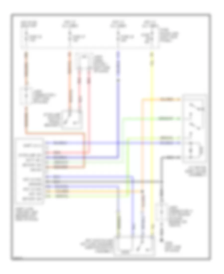
SHIFT INTERLOCKS
Shift Interlock Wiring Diagram for Infiniti Q45 1997
List of elements for Shift Interlock Wiring Diagram for Infiniti Q45 1997:

ANTI-LOCK BRAKESANTI-THEFTBODY COMPUTERAIR CONDITIONINGCOOLING FANELECTRONIC POWER STEERINGDEFOGGERSEXTERIOR LIGHTSCRUISE CONTROLGROUND DISTRIBUTIONENGINE PERFORMANCECOMPUTER DATA LINESHORNHEADLIGHTSPOWER DOOR LOCKSINTERIOR LIGHTSPOWER DISTRIBUTIONPOWER MIRRORSMEMORY SYSTEMSINSTRUMENT CLUSTERPOWER ANTENNAPOWER TOP/SUNROOFPOWER SEATSPOWER WINDOWSSTARTING/CHARGINGSUPPLEMENTAL RESTRAINTSWARNING SYSTEMSSHIFT INTERLOCKSTRUNK, TAILGATE, FUEL DOORTRANSMISSIONRADIOWIPER/WASHER