WARNING SYSTEMS
Warning System Wiring Diagrams for Infiniti Q45 1997
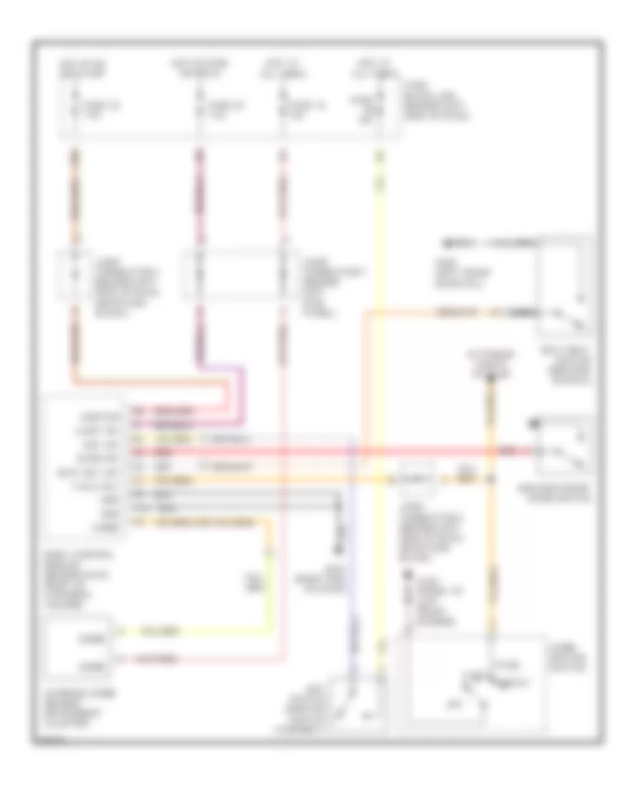
List of elements for Warning System Wiring Diagrams for Infiniti Q45 1997:
- 18b
- Auto
- Body control module (behind dash, right of steering column)
- Chime
- Comb- ination switch
- Door sw
- Driver's front door switch
- Exterior lights system
- Fuse 10a
- Fuse 12 10a
- Fuse 22 7.5a
- Fuse 32 7.5a
- Fuse block (j/b) (behind left side of dash)
- G100 (front of left front fender)
- G201 (right end of dash)
- G309 (left front door sill)
- Grd
- Head
- Hot at all times
- Hot in on or start
- Hot in park or head
- Ignition
- Joint connector 2 (behind left side of dash, near fuse block)
- Joint connector 3 (behind left side of dash, near fuse block)
- Joint connector 7 (behind left kick panel)
- Key sw
- Key switch (ignition switch assembly)
- Light sw
- Nca
- Off
- Park
- Red
- Seat belt switch (driver's buckle)
- Seat blt sw
- Tail/l rly
- Warning chime (behind instrument cluster)
 English