
 Čeština
 Dansk
Dansk Deutsch
 English
 English
 Español
 Suomi
Suomi Français
 Français
 עברית
עברית Hrvatski
 Magyar
 Italiano
 日本語
日本語 한국어
한국어 Nederlands
 Polski
 Português
 Português
 Română
 Русский
 Slovenčina
 Slovenščina
 Svenska
 Türkçe
 中文 (中国)

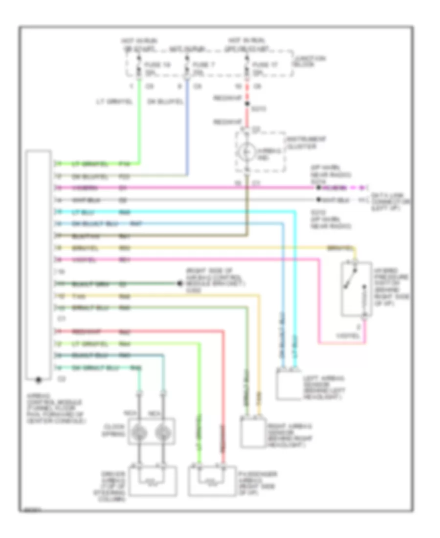
SUPPLEMENTAL RESTRAINTS
Supplemental Restraint Wiring Diagram for Dodge Intrepid 1997
List of elements for Supplemental Restraint Wiring Diagram for Dodge Intrepid 1997:

ANTI-LOCK BRAKESANTI-THEFTAIR CONDITIONINGCOOLING FANCOMPUTER DATA LINESCRUISE CONTROLBODY COMPUTERDEFOGGERSHEADLIGHTSENGINE PERFORMANCEGROUND DISTRIBUTIONHORNEXTERIOR LIGHTSINSTRUMENT CLUSTERPOWER ANTENNAELECTRONIC POWER STEERINGPOWER DISTRIBUTIONPOWER DOOR LOCKSINTERIOR LIGHTSPOWER SEATSPOWER MIRRORSPOWER WINDOWSSTARTING/CHARGINGPOWER TOP/SUNROOFTRUNK, TAILGATE, FUEL DOORWARNING SYSTEMSRADIOTRANSMISSIONSUPPLEMENTAL RESTRAINTSWIPER/WASHER