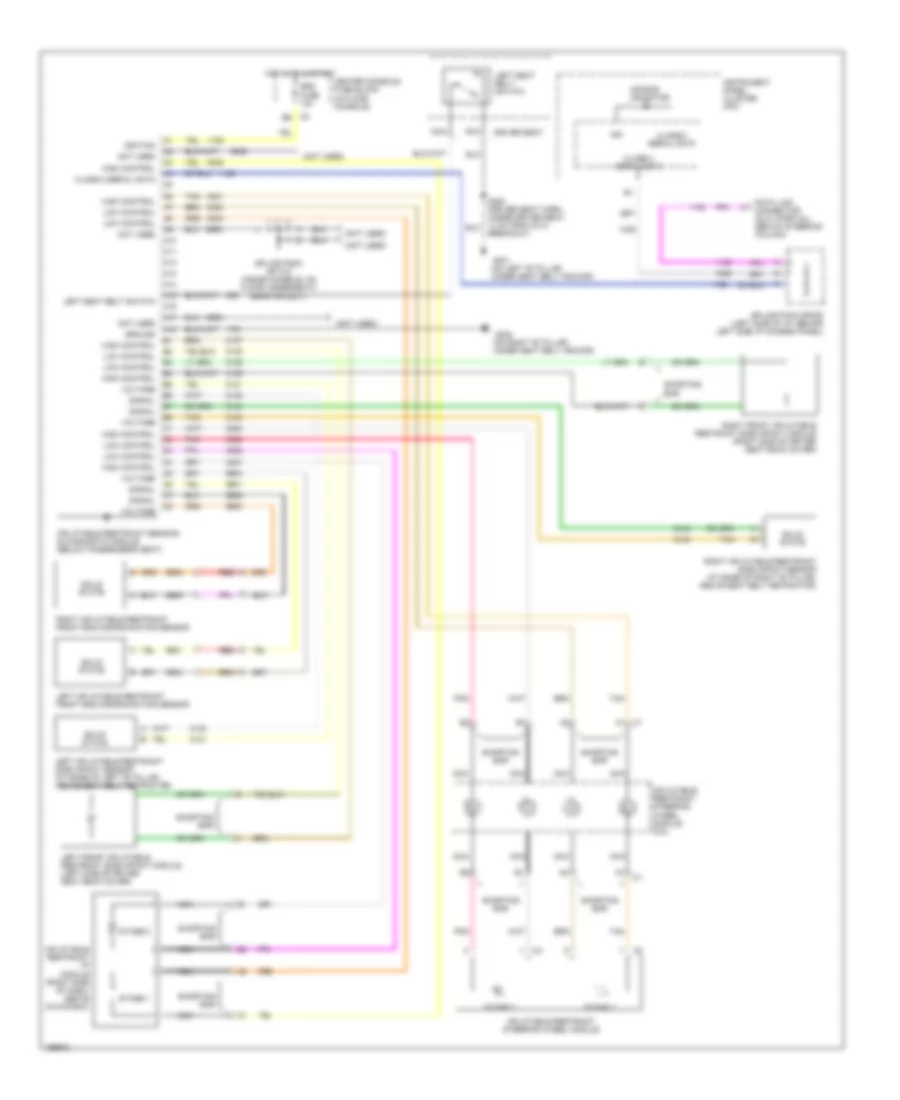
SUPPLEMENTAL RESTRAINTS
Supplemental Restraints Wiring Diagram for Buick Rendezvous CX 2003
List of elements for Supplemental Restraints Wiring Diagram for Buick Rendezvous CX 2003:
- (not used)
- (on left "b" pillar, under seat belt anchor)
- (on right "b" pillar, under seat belt anchor)
- A10
- A11
- A12
- A13
- A14
- A15
- A16
- A17
- A18
- Air bag indicator
- Bar
- Breakout)
- C1 a1
- Center console fuse block (in floor console)
- Class 2 serial data
- Data link connector (dlc) (partial) (below steering column)
- Driver seat
- G301
- G302
- Ground
- High control
- Hot in on & start
- Ign
- Ignition
- Inflatable restraint i/p module (right side of dash, above glove box)
- Inflatable restraint sensing & diagnostic module (below passenger's seat)
- Inflatable restraint steering wheel module
- Inflatable restraint steering wheel module coil
- Instrument panel cluster (ipc)
- Left front inflatable restraint side impact module (left side of driver seat back cover)
- Left inflatable restraint front end discriminating sensor
- Left inflatable restraint side impact sensor (at base of left "b" pillar, above seat belt retractor)
- Left seat belt switch
- Low control
- Nca
- Not used
- Pnk
- Red
- Right front inflatable restraint side impact module (right side of driver seat back cover)
- Right inflatable restraint front end discriminating sensor
- Right inflatable restraint side impact sensor (at base of right "b" pillar, above seat belt retractor)
- Shorting
- Shorting bar
- Signal
- Solid state
- Splice pack sp 315 (inside console, on floor underneath rear air duct)
- Splice pack sp205 (left side of i/p, behind left side i/p access panel)
- Srs fuse 10a
- Stage 1
- Stage 2
- Tan
- Voltage
 Čeština
 Dansk
Dansk Deutsch
 English
 English
 Español
 Suomi
Suomi Français
 Français
 עברית
עברית Hrvatski
 Magyar
 Italiano
 日本語
日本語 한국어
한국어 Nederlands
 Polski
 Português
 Português
 Română
 Русский
 Slovenčina
 Slovenščina
 Svenska
 Türkçe
 中文 (中国)
 Ελληνικά