
 Čeština
 Dansk
Dansk Deutsch
 English
 English
 Español
 Suomi
Suomi Français
 Français
 עברית
עברית Hrvatski
 Magyar
 Italiano
 日本語
日本語 한국어
한국어 Nederlands
 Polski
 Português
 Português
 Română
 Русский
 Slovenčina
 Slovenščina
 Svenska
 Türkçe
 中文 (中国)

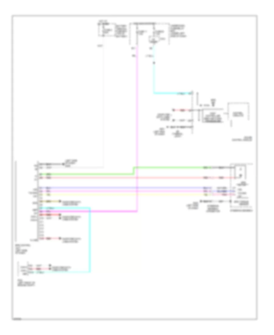
ELECTRONIC POWER STEERING
Electronic Power Steering Wiring Diagram for Honda Insight EX 2014
List of elements for Electronic Power Steering Wiring Diagram for Honda Insight EX 2014:

ANTI-LOCK BRAKESAIR CONDITIONINGANTI-THEFTCOMPUTER DATA LINESBODY CONTROL MODULESCRUISE CONTROLDEFOGGERSENGINE PERFORMANCECOOLING FANEXTERIOR LIGHTSGROUND DISTRIBUTIONHEADLIGHTSELECTRONIC POWER STEERINGHORNINTERIOR LIGHTSPOWER MIRRORSINSTRUMENT CLUSTERPOWER DOOR LOCKSNAVIGATIONPOWER WINDOWSPOWER DISTRIBUTIONSHIFT INTERLOCKRADIOSUPPLEMENTAL RESTRAINTSTRANSMISSIONSTARTING/CHARGINGTRUNK, TAILGATE, FUEL DOORWARNING SYSTEMSWIPER/WASHER