AIR CONDITIONING
A/C Wiring Diagram for Ford Contour GL 1997
 https://portal-diagnostov.com/license.html
Automotive Electricians Portal FZCO
Automotive Electricians Portal FZCO
https://portal-diagnostov.com/license.html
https://portal-diagnostov.com/license.html
Automotive Electricians Portal FZCO
Automotive Electricians Portal FZCO
List of elements for A/C Wiring Diagram for Ford Contour GL 1997:
- (behind bottom of right kick panel)
- (engine cooling fan harness, near electric cooling fan motor breakout)
- (fuse box harn, behind left side of i/p)
- (i/p harn, behind right center of i/p)
- (left front of engine compartment, behind headlamp)
- (right front of engine compartment, near headlamps)
- (right front of engine compt, near headlamps)
- 14s
- 2.0l
- 2.5l
- 91s
- A/c clutch cycling pressure switch (left front of engine compartment)
- A/c clutch diode
- A/c clutch relay (in engine compartment fuse box)
- A/c clutch solenoid
- A/c high pressure cutout/fan switch (right front corner of engine compartment)
- A/c wide open throttle relay (in engine compartment fuse box)
- Air temperature actuator (under right center of i/p, left of glove box)
- Air temperature control
- Backup lamps fuse 23 15a
- Blower motor
- Blower motor fuse 37 30a
- Blower motor relay
- Blower motor resistor (under right center of i/p)
- Blower switch
- C281
- Clutch switch
- Cool
- Cooling fan resistor (lower left corner of cooling fan shroud)
- Def
- Electric cooling fan motor
- Electric cooling fan motor #1
- Electric cooling fan motor #2
- Engine compartment fuse box
- Engine compt)
- Engine cooling fan fuse 2 60a
- Fan switch
- Flr
- Flr/def
- G100
- G100 (left front of engine compartment, behind headlamp)
- G101
- G101 (right front of engine compart- ment, near headlamps)
- G203
- G203 (behind bottom of right kick panel)
- Gearshift lever unit
- Heater/ a/c mode switch
- High speed cooling fan relay (in engine compartment fuse box)
- Hot at all times
- Hot in run or start
- Interior fuse panel
- Low speed cooling fan relay (in engine compartment fuse box)
- Max a/c
- Nca
- Norm a/c
- Off
- Pan/flr
- Pan/vnt
- Pcm power relay
- Powertrain control module (right rear corner of engine compartment)
- Red
- S107 (fuse box harn, left side of engine compt)
- S124
- S124 (engine cooling fan harness, near electric cooling fan motor breakout)
- S125 (engine cooling fan harn, right front side of engine compt)
- S126 (engine cooling fan harn, near a/c clutch solenoid)
- S167 (engine control harn, near pcm breakout)
- S171 (fuse box harn, front center of engine compt)
- S216 (i/p harn, near i/p cluster breakout)
- S218
- S223 (i/p harn, near main light sw breakout)
- S242
- S243 (fuse box harn, behind left side of i/p)
- S245 (i/p harn, near top of glove box)
- S247 (i/p harn, near top of glove box)
- Shorting bar connector #1 (behind left side of i/p)
- Shorting bar connector #3 (behind right side of i/p)
- Warm
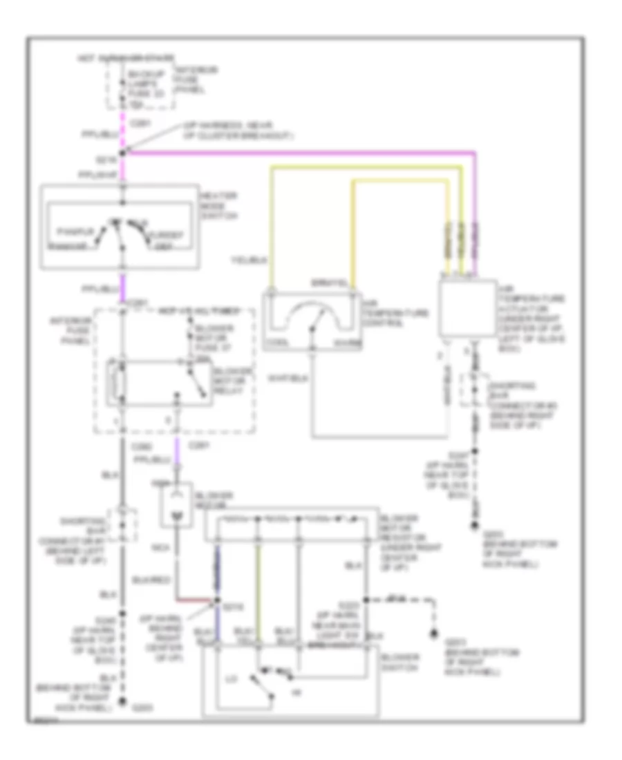
Heater Wiring Diagram for Ford Contour GL 1997
List of elements for Heater Wiring Diagram for Ford Contour GL 1997:
- (behind bottom
- (i/p harn, behind right center of i/p)
- (i/p harness, near i/p cluster breakout)
- Air temperature actuator (under right center of i/p, left of glove box)
- Air temperature control
- Backup lamps fuse 23 15a
- Blower motor
- Blower motor fuse 37 30a
- Blower motor relay
- Blower motor resistor (under right center of i/p)
- Blower switch
- C281
- C282
- Cool
- Def
- Flr
- Flr/def
- Fuse
- G203
- G203 (behind bottom of right kick panel)
- Heater mode switch
- Hot at all times
- Hot in run or start
- Interior
- Interior fuse panel
- Kick panel)
- Nca
- Of right
- Off
- Pan/flr
- Pan/vnt
- Panel
- S216
- S218
- S223 (i/p harn, near main light sw breakout)
- S245 (i/p harn, near top of glove box)
- Shorting bar connector #1 (behind left side of i/p)
- Shorting bar connector #3 (behind right side of i/p)
- Warm
 Čeština
 Dansk
Dansk Deutsch
 English
 English
 Español
 Suomi
Suomi Français
 Français
 עברית
עברית Hrvatski
 Magyar
 Italiano
 日本語
日本語 한국어
한국어 Nederlands
 Polski
 Português
 Português
 Română
 Русский
 Slovenčina
 Slovenščina
 Svenska
 Türkçe
 中文 (中国)
 Ελληνικά