AIR CONDITIONING
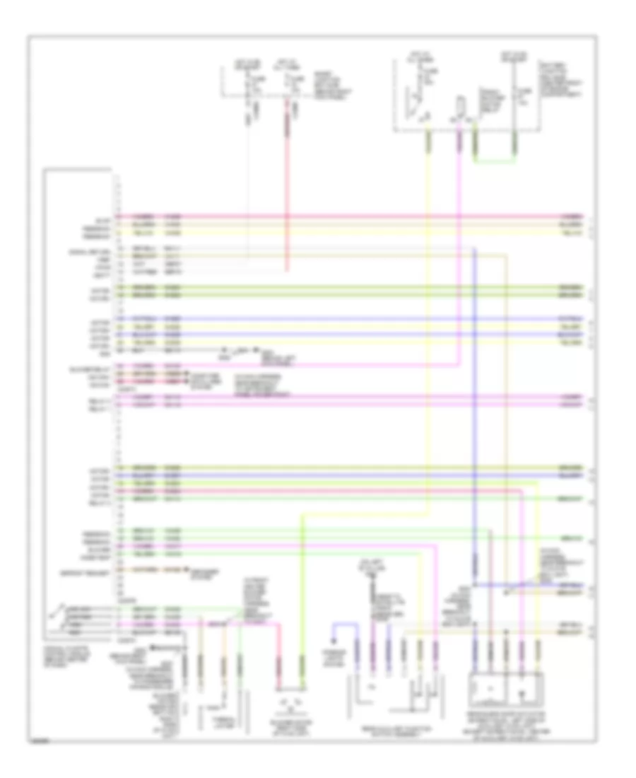
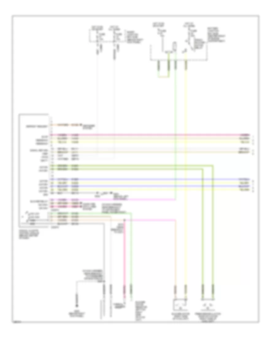
Automatic A/C Wiring Diagram, with Auxiliary Climate Control (1 of 3) for Ford Expedition 2007
 https://portal-diagnostov.com/license.html
Automotive Electricians Portal FZCO
Automotive Electricians Portal FZCO
https://portal-diagnostov.com/license.html
https://portal-diagnostov.com/license.html
Automotive Electricians Portal FZCO
Automotive Electricians Portal FZCO
List of elements for Automatic A/C Wiring Diagram, with Auxiliary Climate Control (1 of 3) for Ford Expedition 2007:
- (bottom left side of hvac unit) driver temperature blend door actuator
- (in console panel harness, near to satellite radio receiver) s349
- (in front heater blower motor harness, near breakout to c299) s217
- (left side of hvac unit) mode door actuator
- (near breakout to driver temperature blend door actuator) s220
- (near breakout to glove box light)
- (near breakout to instrument panel power point)
- (near breakout to passenger air bag module) s227
- (on left "b" pillar) g301
- (right side of hvac unit) fresh/ recirculation door actuator
- Ambient signal
- Battery junction box (bjb) (center front of engine compartment)
- Blower
- Blower motor (right side of hvac unit)
- Blower relay
- C228a
- C228b
- Cbp37
- Ch112
- Ch113
- Ch114
- Ch122
- Ch123
- Ch202
- Ch203
- Ch207
- Ch208
- Ch212
- Ch213
- Ch228
- Ch229
- Ch233
- Ch234
- Ch238
- Ch239
- Ch402
- Ch447
- Computer data lines system
- Defogger system
- Defrost request
- Driver sunload
- Electronic automatic temperature control (eatc) module (in center of dash)
- Evap
- Except expedition el
- Expedition el
- Feedback
- Front blower motor relay
- Fuse 10a
- Fuse 40a
- G200 (behind right kick panel)
- G203 (behind left kick panel)
- Gd113
- Gd138
- Gnd
- Heater blower motor control module (right side of hvac unit)
- Hot at all times
- Hot in on or start
- Humidity signal
- In-vehicle signal
- Interior lights system
- Lh111
- Lh115
- Mode/temp
- Motor+
- Motor-
- Ms can+
- Ms can-
- Passenger sunload
- Passenger temperature blend door actuator (top front of hvac unit)
- Rear auxiliary function switch assembly
- Rear mode door actuator (expedition el: left side of hvac unit) (except expedition el: top left side of hvac unit)
- Redundant cc signal
- Relay 1
- Relay 2
- Relay 3
- Rh111
- S219 (near breakout to passenger temperature blend door actuator)
- S222
- S223
- S228
- Sbp15
- Signal return
- Variable blower control
- Vbatt
- Vdb06
- Vdb07
- Vh101
- Vh301
- Vh406
- Vh407
- Vh413
- Vh414
- Vh416
- Vh417
- Vh436
- Vh438
- Vh439
- Vh440
- Vh441
- Vha15
- Vha17
- Vpwr
- Vref
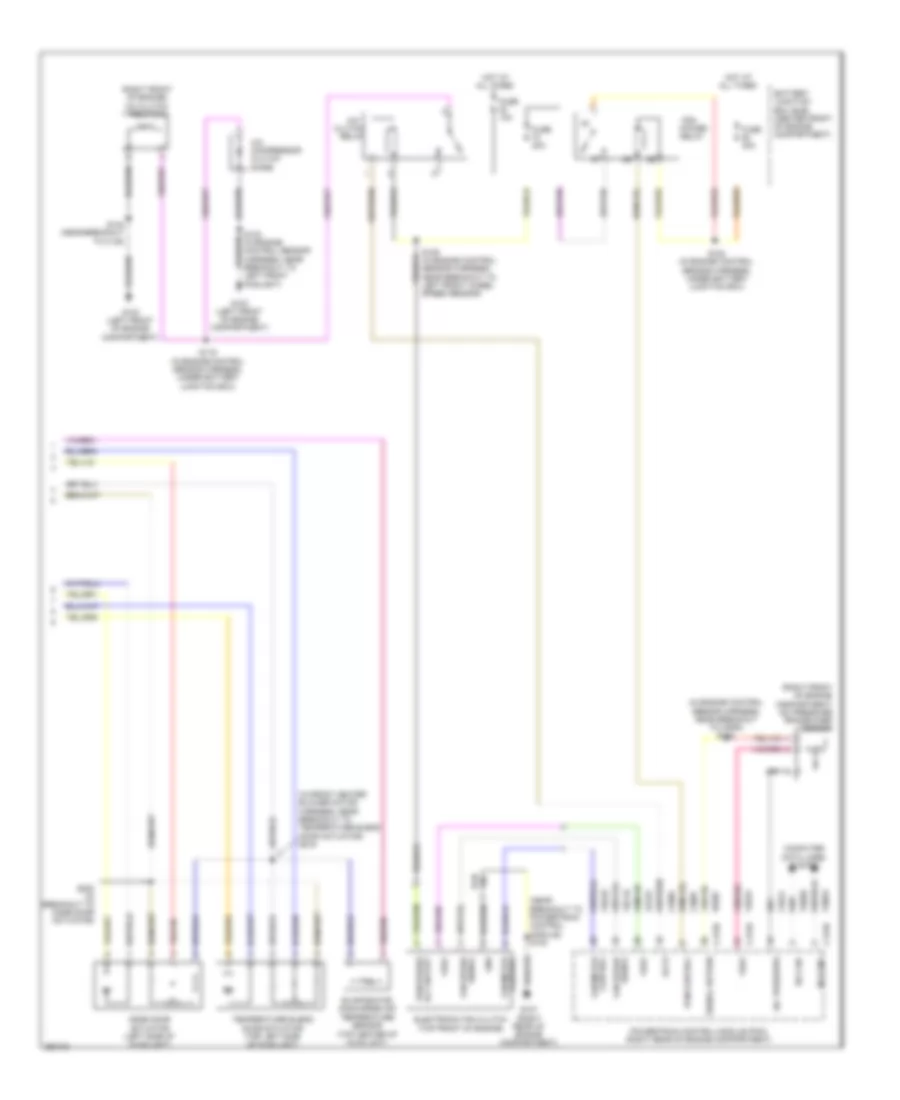
Automatic A/C Wiring Diagram, with Auxiliary Climate Control (2 of 3) for Ford Expedition 2007
List of elements for Automatic A/C Wiring Diagram, with Auxiliary Climate Control (2 of 3) for Ford Expedition 2007:
- (behind front of radiator grille) ambient air temperature sensor
- (behind left side of dash) (navigator) in-vehicle temperature/ humidity sensor
- (behind left side of dash) in-vehicle temperature sensor
- (top center of hvac unit) evaporator discharge air temperature sensor
- (under top center of dash) sunload sensor
- C218a
- C218b
- C2280e
- C2280f
- C2280g
- Clock spring (in steering wheel)
- Except expedition el
- Expedition
- Expedition el
- Fan+
- Fan-
- Fuse 10a
- Fuse 7.5a
- Head- lights system
- Hot at all times
- Hot in on or start
- Left steering wheel switch
- Navigator
- Rear blend door actuator (expedition el: left side of hvac unit) (except expedition el: center of auxiliary hvac unit)
- Right steering wheel switch
- S410 (except expedition el) (in breakout to rear mode door actuator) s430 (expedition el) (in auxiliary case jumper, near breakout to rear mode door actuator)
- S411 (except expedition el) (in breakout to rear mode door actuator) s429 (expedition el) (in auxiliary case jumper, near breakout to rear mode door actuator)
- Smart junction box (sjb) (behind right kick panel)
- Solid state
- Temp+
- Temp-
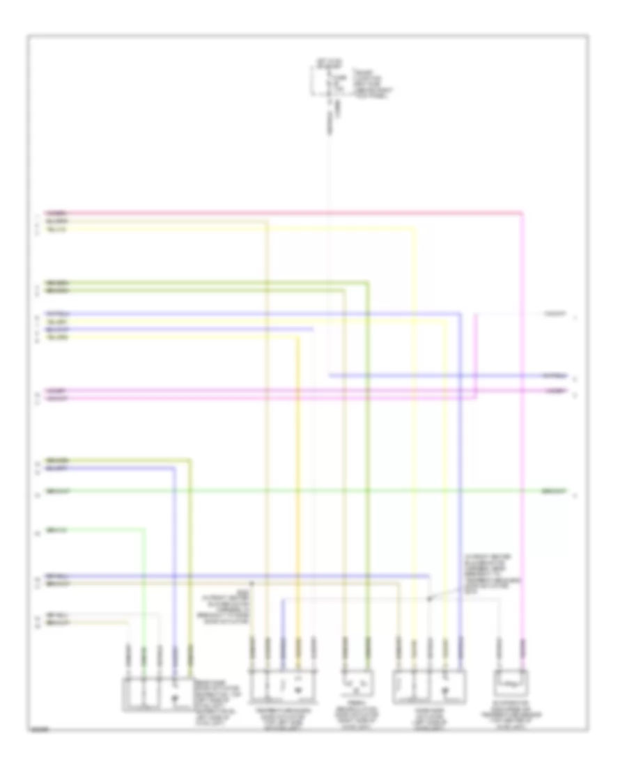
Automatic A/C Wiring Diagram, with Auxiliary Climate Control (3 of 3) for Ford Expedition 2007
List of elements for Automatic A/C Wiring Diagram, with Auxiliary Climate Control (3 of 3) for Ford Expedition 2007:
- (in engine control sensor & fuel charge harness, near breakout to c145) s140
- (in engine control sensor harness, near breakout to horn) s122
- (left front of engine compartment) g103
- (navigator: near breakout to auxiliary relay box 2) (except navigator: breakout to right rear quarter window motor) s417
- (near breakout to powertrain control module)
- (right rear of engine compartment)
- A/c clutch field coil (right front of engine)
- A/c clutch relay
- A/c compressor clutch diode
- A/c pressure
- A/c pressure transducer sensor (right front of engine compt)
- Accr
- Auxiliary blower motor (right side of auxiliary hvac unit)
- Auxiliary blower motor resistor assembly (right side of auxiliary hvac unit)
- Auxiliary relay box 2 (right rear corner of vehicle)
- Battery junction box (bjb) (center front of engine compartment)
- C175b
- C175e
- Ce607
- Ch302
- Ch421
- Computer data lines system
- Control fan motor
- Electronic fan clutch (top front of engine)
- Except expedition el
- Expedition el
- Fan motor control
- Fan speed signal
- Fuse 10a
- Fuse 20a
- Fuse 30a
- G103 (left front of engine compartment)
- G107
- G403 (navigator: left rear corner of vehicle) (except navigator: right rear corner of vehicle)
- Gnd
- Hot at all times
- Hs can+
- Hs can-
- Le423
- Pcm control
- Pcm power relay
- Pcm power rly sw out
- Powertrain control module (pcm) (right rear of engine compartment)
- Re407
- Rear blower motor relay 1
- Rear blower motor relay 2
- Rear blower motor relay 3
- S102
- S106 (in engine control sensor harness, near breakout to left front wheel speed sensor)
- S119 (in engine control sensor harness, under battery junction box)
- S120 (in engine control sensor harness, under battery junction box)
- S418 (w/ power vent windows) (navigator: breakout to g402) (except navigator: near breakout right rear quarter window motor)
- S422 (expedition el) (near breakout to c408) s414 (except expedition el) (near breakout to g402)
- S428 (near breakout to rear mode door actuator) s412 (near breakout to auxiliary blower motor resistor assembly)
- Signal return
- Thermal limiter
- Vdb04
- Vdb05
- Vec03
- Vec10
- Vh433
- Vref
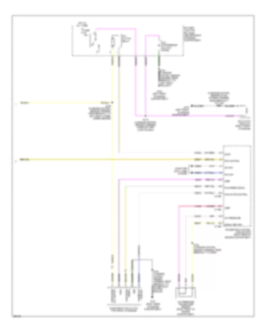
Automatic A/C Wiring Diagram, without Auxiliary Climate Control (1 of 3) for Ford Expedition 2007
List of elements for Automatic A/C Wiring Diagram, without Auxiliary Climate Control (1 of 3) for Ford Expedition 2007:
- (expedition: in main harness, near breakout to instrument panel power point)
- (near breakout glove box light) s223
- (near breakout to driver temperature blend door actuator) s220
- (near breakout to passenger temperature blend door actuator) s219
- (right side of hvac unit) fresh/ recirculation door actuator
- (under top center of dash) sunload sensor
- Ambient signal
- Blower relay
- C2280f
- C2280g
- C228a
- C228b
- Cbp37
- Ch122
- Ch123
- Ch202
- Ch203
- Ch212
- Ch213
- Ch228
- Ch229
- Ch238
- Ch239
- Ch447
- Computer data lines system
- Defogger system
- Defrost request
- Driver sunload
- Driver temperature blend door actuator (bottom left side of hvac unit)
- Electronic automatic temperature control (eatc) module (in center of dash)
- Evap
- Evaporator discharge air temperature sensor (top center of hvac unit)
- Feedback
- Fuse 10a
- G203 (behind left kick panel)
- Gd113
- Gnd
- Head- lights system
- Hot at all times
- Hot in on or start
- In-vehicle signal
- Lh111
- Mode door actuator (left side of hvac unit)
- Motor+
- Motor-
- Ms can+
- Ms can-
- Passenger sunload
- Passenger temperature blend door actuator (top front of hvac unit)
- Redundant cc signal
- S228
- Sbp15
- Smart junction box (sjb) (behind right kick panel)
- Solid state
- Variable blower control
- Vbatt
- Vdb06
- Vdb07
- Vh101
- Vh406
- Vh407
- Vh414
- Vh416
- Vh417
- Vh436
- Vh440
- Vh441
- Vpwr
- Vref
Automatic A/C Wiring Diagram, without Auxiliary Climate Control (2 of 3) for Ford Expedition 2007
List of elements for Automatic A/C Wiring Diagram, without Auxiliary Climate Control (2 of 3) for Ford Expedition 2007:
- (behind front of radiator grille) ambient air temperature sensor
- (behind left side of dash) in-vehicle temperature sensor
- (in front heater blower motor harness, near breakout to c299) s217
- (in main harness, near breakout to passenger air bag module) s227
- Battery junction box (bjb) (center front of engine compartment)
- Blower motor (right side of hvac unit)
- C218a
- C218b
- Ch402
- Clock spring (in steering wheel)
- Fan+
- Fan-
- Front blower motor relay
- Fuse 10a
- Fuse 20a
- Fuse 30a
- Fuse 40a
- G200 (behind right kick panel)
- Gd138
- Heater blower motor control module (right side of hvac unit)
- Hot at all times
- Hot in on or start
- Left steering wheel switch
- Pcm power relay
- Right steering wheel switch
- S120 (in engine control sensor harness, under battery junction box)
- Temp+
- Temp-
- Vh101
- Vh301
Automatic A/C Wiring Diagram, without Auxiliary Climate Control (3 of 3) for Ford Expedition 2007
List of elements for Automatic A/C Wiring Diagram, without Auxiliary Climate Control (3 of 3) for Ford Expedition 2007:
- (in engine control sensor & fuel charge harness, near breakout to c145) s140
- (right rear of engine compartment)
- A/c clutch field coil (right front of engine)
- A/c clutch relay
- A/c compressor clutch diode
- A/c pressure
- A/c pressure transducer sensor (right front of engine compartment)
- Accr
- Battery junction box (bjb) (center front of engine compartment)
- C175b
- C175e
- Ce607
- Ch302
- Ch421
- Computer data lines system
- Control fan motor
- Electronic fan clutch (top front of engine)
- Fan motor control
- Fan speed signal
- Fuse 10a
- G103 (left front of engine compartment)
- G107
- Gnd
- Hot at all times
- Hs can+
- Hs can-
- Le423
- Pcm control
- Pcm power rly sw out
- Powertrain control module (pcm) (right rear of engine compartment)
- Re407
- S102 (in engine control sensor harness, near breakout to powertrain control module)
- S106 (in engine control sensor harness, near breakout to left front wheel speed sensor)
- S119 (in engine control sensor harness, under battery junction box)
- S122 (in engine control sensor harness, near breakout to horn)
- Signal return
- Vdb04
- Vdb05
- Vec03
- Vec10
- Vh433
- Vref
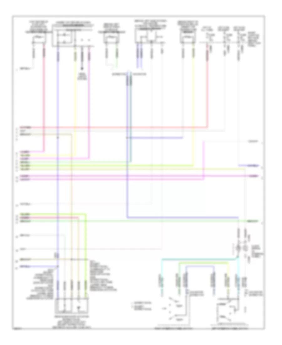
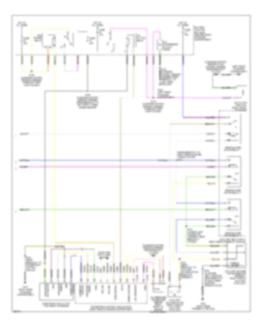
Manual A/C Wiring Diagram, with Auxiliary Climate Control (1 of 3) for Ford Expedition 2007
List of elements for Manual A/C Wiring Diagram, with Auxiliary Climate Control (1 of 3) for Ford Expedition 2007:
- (in front heater blower motor harness, near breakout to c237)
- (in main harness, near breakout to glove box light) s222
- (in main harness, near breakout to instrument panel power point)
- (near to satellite radio receiver) s349
- (on left "b" pillar) g301
- Battery junction box (bjb) (center front of engine compartment)
- Blower
- Blower motor (right side of hvac unit)
- Blower motor resistor (bottom right side of hvac unit)
- Blower relay
- C2280f
- C2280g
- C2357a
- C2357b
- C2357c
- Cbp37
- Ch112
- Ch113
- Ch114
- Ch122
- Ch123
- Ch202
- Ch203
- Ch207
- Ch208
- Ch228
- Ch229
- Ch233
- Ch234
- Ch238
- Ch239
- Ch428
- Ch429
- Ch430
- Computer data lines system
- Defogger system
- Defrost request
- Evap
- Feedback
- Front blower motor relay
- Fuse 10a
- Fuse 40a
- G200 (behind right kick panel)
- G203 (behind left kick panel)
- Gd113
- Gd138
- Gnd
- High
- Hot at all times
- Hot in on or start
- Interior lights system
- Lh111
- Manual climate control module (behind center of dash)
- Mid high
- Mid low
- Mode/temp
- Motor+
- Motor-
- Ms can+
- Ms can-
- Rear auxiliary function switch assembly
- Rear blend door actuator (expedition el: left side of auxiliary hvac unit) (except expedition el: center of auxiliary hvac unit)
- Relay 1
- Relay 2
- Relay 3
- Rh111
- S218
- S223 (in main harness, near breakout to glove box light)
- S227 (in main harness, near breakout to passenger air bag module)
- S228
- Sbp15
- Signal return
- Smart junction box (sjb) (behind right kick panel)
- Thermal limiter
- Vbatt
- Vdb06
- Vdb07
- Vh406
- Vh436
- Vh438
- Vh439
- Vh440
- Vha15
- Vha17
- Vpwr
- Vref
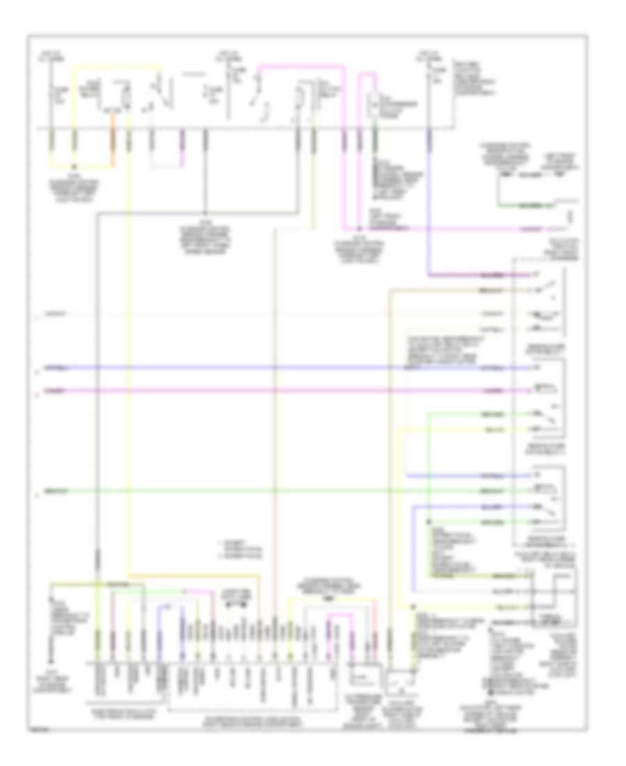
Manual A/C Wiring Diagram, with Auxiliary Climate Control (2 of 3) for Ford Expedition 2007
List of elements for Manual A/C Wiring Diagram, with Auxiliary Climate Control (2 of 3) for Ford Expedition 2007:
- (in front heater blower motor harness, near breakout to temperature blend door actuator) s219
- C2280e
- Evaporator discharge air temperature sensor (top center of hvac unit)
- Fresh/ recirculation door actuator (right side of hvac unit)
- Fuse 7.5a
- Hot in on or start
- Mode door actuator (left side of hvac unit)
- Rear mode door actuator (expedition: top left side of hvac unit) (expedition el: left side of hvac unit)
- S220 (in front heater blower motor harness, in breakout to mode door actuator)
- Smart junction box (sjb) (behind right kick panel)
- Temperature blend door actuator (top left side of hvac unit)
Manual A/C Wiring Diagram, with Auxiliary Climate Control (3 of 3) for Ford Expedition 2007
List of elements for Manual A/C Wiring Diagram, with Auxiliary Climate Control (3 of 3) for Ford Expedition 2007:
- (in engine control sensor & fuel charge harness, near breakout to c145) s140
- (in engine control sensor harness, near breakout to horn) s122
- (left front of engine compartment) g103
- (near breakout to right rear quarter window motor) s417
- (right rear corner of vehicle)
- (right rear of engine compartment)
- A/c clutch field coil (right front of engine)
- A/c clutch relay
- A/c compressor clutch diode
- A/c pressure
- A/c pressure transducer sensor (right front of engine compartment)
- Accr
- Auxiliary blower motor (right side of auxiliary hvac unit)
- Auxiliary blower motor resistor assembly (right side of auxiliary hvac unit)
- Auxiliary relay box 2 (right rear corner of vehicle)
- Battery junction box (bjb) (center front of engine compartment)
- C175b
- C175e
- Ce607
- Ch302
- Ch421
- Computer data lines system
- Control
- Control fan motor
- Electronic fan clutch (top front of engine)
- Fan motor
- Fan speed
- Fuse 10a
- Fuse 20a
- Fuse 30a
- G103 (left front of engine compartment)
- G107
- G403
- Gnd
- Hot at all times
- Hs can+
- Hs can-
- Le423
- Pcm control
- Pcm power relay
- Pcm power rly sw out
- Powertrain control module (pcm) (right rear of engine compartment)
- Re407
- Rear blower motor relay 1
- Rear blower motor relay 2
- Rear blower motor relay 3
- S102 (near breakout to powertrain control module)
- S106 (in engine control sensor harness, near breakout to left front wheel speed sensor)
- S119 (in engine control sensor harness, under battery junction box)
- S120 (in engine control sensor harness, under battery junction box)
- S412 (near breakout to auxiliary blower motor resistor assembly)
- S414 (in rear light connector harness, near breakout to g402)
- S418 (w/ power vent windows) (near breakout to right rear quarter window motor)
- Signal
- Signal fan speed
- Signal return
- Thermal limiter
- Vdb04
- Vdb05
- Vec03
- Vec10
- Vh433
- Vref
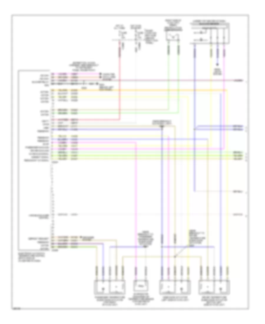
Manual A/C Wiring Diagram, without Auxiliary Climate Control (1 of 2) for Ford Expedition 2007
List of elements for Manual A/C Wiring Diagram, without Auxiliary Climate Control (1 of 2) for Ford Expedition 2007:
- (in main harness, near breakout to instrument panel power point)
- (in main harness, near breakout to passenger air bag module) s227
- Battery junction box (bjb) (center front of engine compartment)
- Blower motor (right side of hvac unit)
- Blower motor resistor (bottom right side of hvac unit)
- Blower relay
- C2280f
- C2280g
- C2357a
- C2357c
- Cbp37
- Ch122
- Ch123
- Ch202
- Ch203
- Ch228
- Ch229
- Ch238
- Ch239
- Ch428
- Ch429
- Ch430
- Computer data lines system
- Defogger system
- Defrost request
- Evap
- Feedback
- Fresh/recirculation door actuator (right side of hvac unit)
- Front blower motor relay
- Fuse 10a
- Fuse 40a
- G200 (behind right kick panel)
- G203 (behind left kick panel)
- Gd113
- Gd138
- Gnd
- High
- Hot at all times
- Hot in on or start
- Lh111
- Manual climate control module (behind center of dash)
- Mid high
- Mid low
- Motor+
- Motor-
- Ms can+
- Ms can-
- Rh111
- S218 (near breakout to c237)
- S228
- Sbp15
- Signal return
- Smart junction box (sjb) (behind right kick panel)
- Thermal limiter
- Vbatt
- Vdb06
- Vdb07
- Vh406
- Vh436
- Vh440
- Vpwr
- Vref
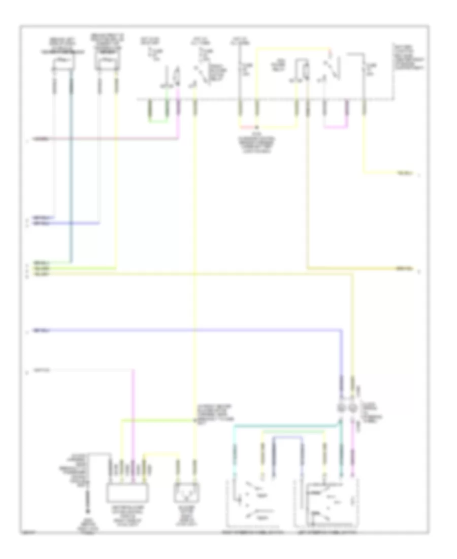
Manual A/C Wiring Diagram, without Auxiliary Climate Control (2 of 2) for Ford Expedition 2007
List of elements for Manual A/C Wiring Diagram, without Auxiliary Climate Control (2 of 2) for Ford Expedition 2007:
- (in engine control sensor harness, near breakout to horn) s122
- (in front heater blower motor harness, near breakout to temperature blend door actuator) s219
- (near breakout to powertrain control module) s102
- (right front of engine compartment) a/c pressure transducer sensor
- (right front of engine) a/c clutch field coil
- (right rear of engine compartment)
- A/c
- A/c compressor clutch diode
- A/c pressure
- Accr
- Battery junction box (bjb) (center front of engine compartment)
- C175b
- C175e
- Ce607
- Ch302
- Ch421
- Clutch
- Computer data lines system
- Control fan motor
- Electronic fan clutch (top front of engine)
- Evaporator discharge air temperature sensor (top center of hvac unit)
- Fuse 10a
- Fuse 20a
- Fuse 30a
- G103 (left front of engine compartment)
- G107
- Gnd
- Hot at all times
- Hs can+
- Hs can-
- Le423
- Mode door actuator (left side of hvac unit)
- Pcm
- Pcm control
- Pcm power rly sw out
- Power relay
- Powertrain control module (pcm) (right rear of engine compartment)
- Re407
- Relay
- S106 (in engine control sensor harness, near breakout to left front wheel speed sensor)
- S119 (in engine control sensor harness, under battery junction box)
- S120 (in engine control sensor harness, under battery junction box)
- S123 (in engine control sensor harness, near breakout to left front foglight)
- S140 (near breakout to c145)
- S220 (in breakout to mode door actuator)
- Signal fan speed
- Signal return
- Temperature blend door actuator (top left side of hvac unit)
- Vdb04
- Vdb05
- Vec03
- Vec10
- Vh433
- Vref

 Čeština
 Dansk
Dansk Deutsch
 English
 English
 Español
 Suomi
Suomi Français
 Français
 עברית
עברית Hrvatski
 Magyar
 Italiano
 日本語
日本語 한국어
한국어 Nederlands
 Polski
 Português
 Português
 Română
 Русский
 Slovenčina
 Slovenščina
 Svenska
 Türkçe
 中文 (中国)