ENGINE PERFORMANCE
5.0L
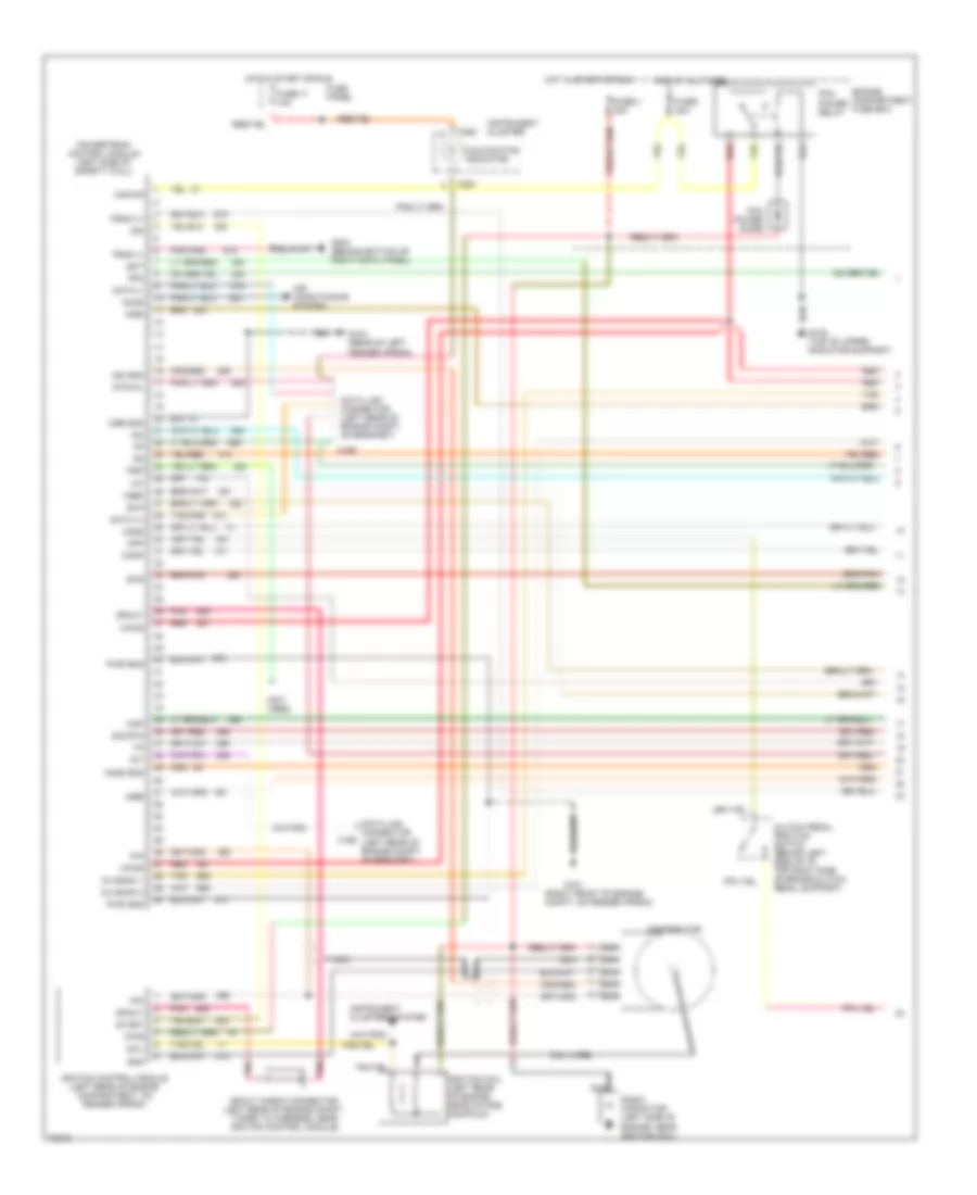
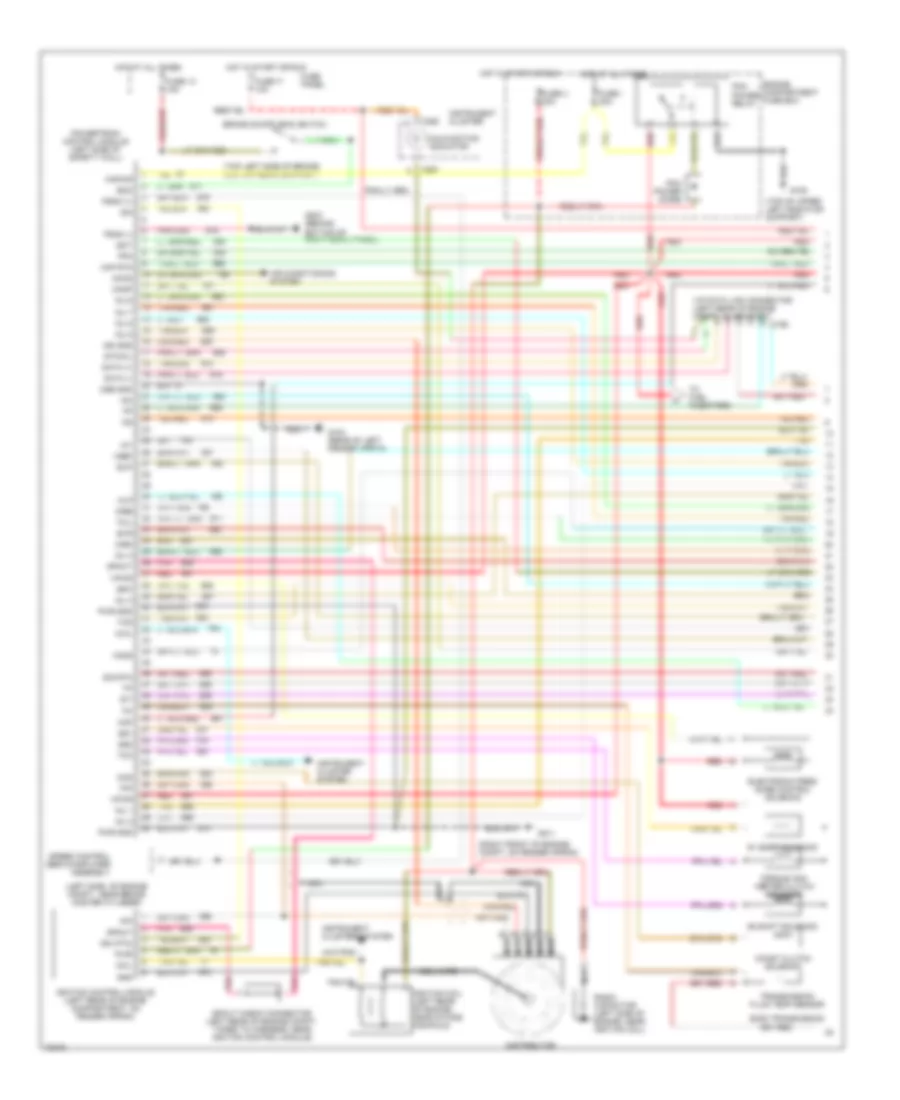
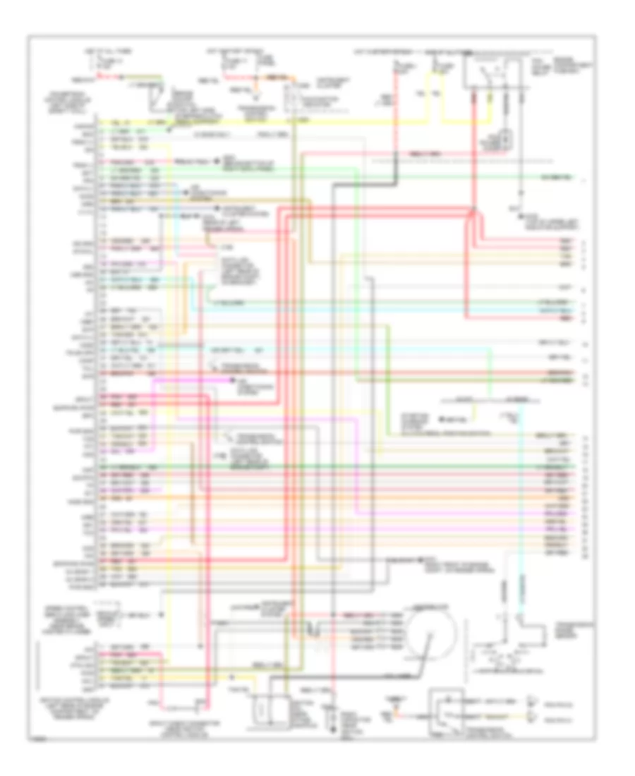
5.0L MFI, Engine Performance Wiring Diagrams (1 of 2) for Ford Bronco 1995
List of elements for 5.0L MFI, Engine Performance Wiring Diagrams (1 of 2) for Ford Bronco 1995:
- (not used)
- (right front of engine compt, on fender apron)
- Accs
- Air conditioning system
- Airb
- Aird
- C198
- C250
- C251
- Canp
- Clutch pedal position switch (behind left side of i/p, top right side of brake/clutch pedal support)
- Coil
- Coil wire
- Cpp
- Cse gnd
- Data (+)
- Data (-)
- Data link connector (left rear of engine compt, on bracket)
- Data link connector c199 (left rear of engine compt, on bracket)
- Distributor
- Ect
- Engine compartment fuse box
- Evp
- Evr
- Fpm
- Fuse 17 10a
- Fuse i 20a
- Fuse panel
- Fuse u 20a
- G101
- G104 (rear of left fender apron)
- G108 (top of upper radiator support)
- G203 (behind bottom of right cowl panel)
- Gnd
- Ho2s
- Ho2s gnd
- Hot at all times
- Hot in start or run
- Iac
- Iat
- Idm
- Ign gnd
- Ignition coil (left rear of engine, near intake manifold)
- Ignition control module (left rear of engine compartment, on fender apron)
- Inj bank 1
- Inj bank 2
- Instrument cluster
- Instrument clusters system
- Kapwr
- Malfunction indicator
- Map
- Nca
- Pcm power diode
- Pcm power relay
- Pip
- Pnk
- Powertrain control module (left side of safety wall)
- Psom (+)
- Psom (-)
- Psp
- Pwr
- Pwr gnd
- Radio capacitor (left side of engine, near ignition coil)
- Red
- Sig rtn
- Spout
- Spout check connector (left rear of engine compt, taped to harness, near ignition control module)
- Start
- Sti
- Sto/mil
- Tan
- Vpwr
- Vref
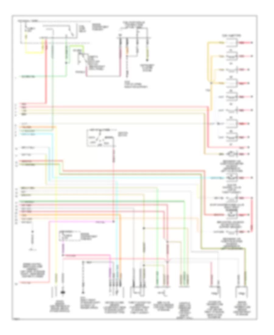
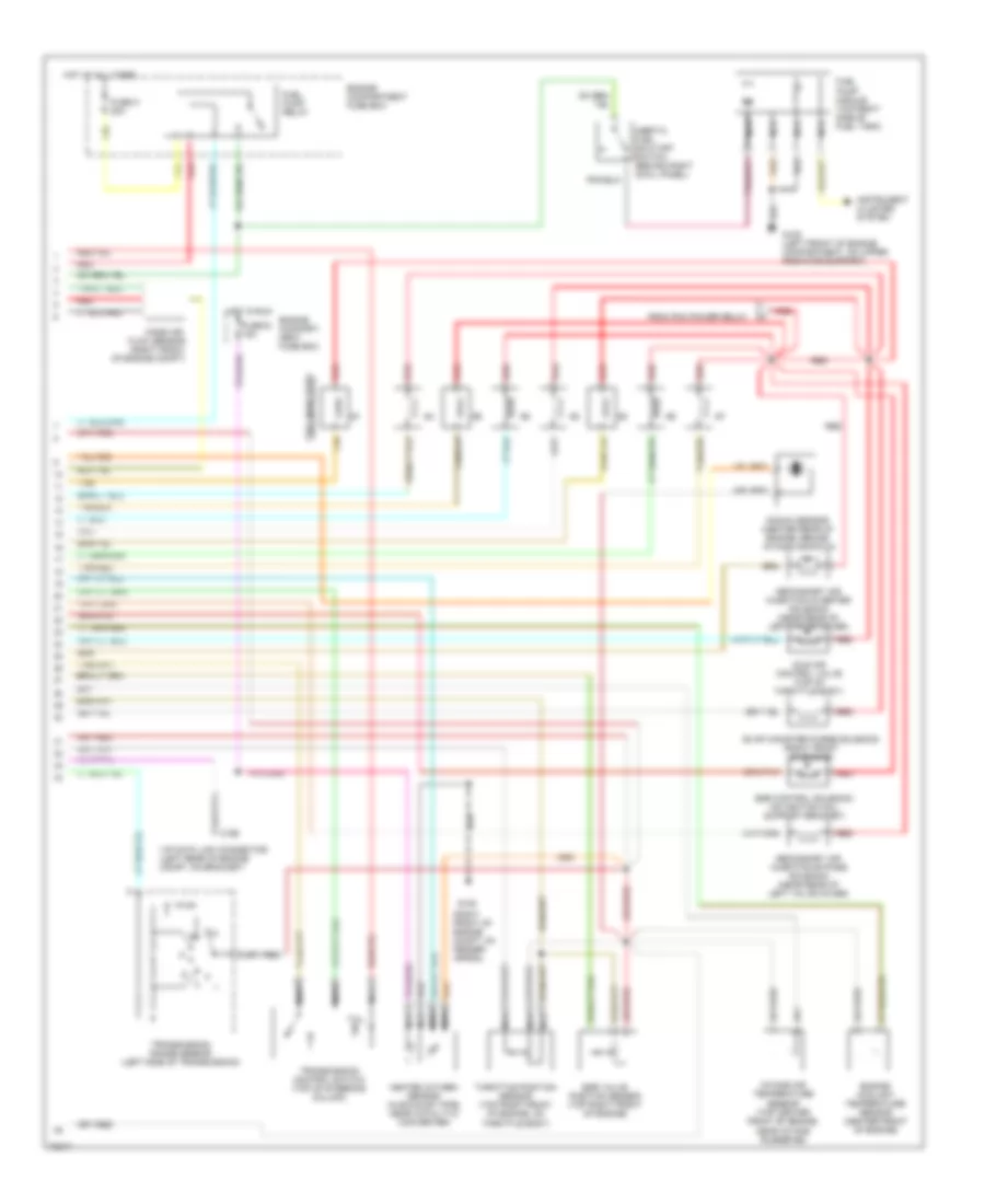
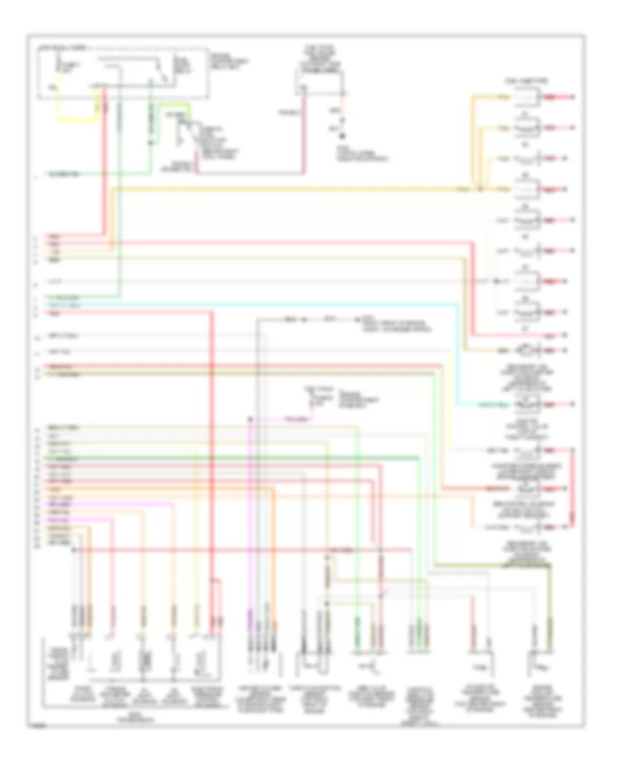
5.0L MFI, Engine Performance Wiring Diagrams (2 of 2) for Ford Bronco 1995
List of elements for 5.0L MFI, Engine Performance Wiring Diagrams (2 of 2) for Ford Bronco 1995:
- (right front of engine)
- Acc
- Egr control solenoid (on ignition coil support bracket)
- Egr valve position sensor (top right front of engine)
- Engine compartment fuse box
- Engine coolant temperature sensor (center front of engine)
- Evap canister purge valve
- Fuel injectors
- Fuel pump module (top right side of fuel tank)
- Fuel pump relay
- Fuse e 15a
- Fuse o 20a
- G101 (right front of engine compt, on front of fender apron)
- G108 (top of upper radiator support)
- Heated oxygen sensor (lower right rear of engine compt, in exhaust pipe)
- Hot at all times
- Hot in run
- Idle air control valve (top of throttle body)
- Ignition switch
- Inertia fuel shut-off switch (behind right cowl panel)
- Instrument cluster system
- Intake air temperature sensor (top center front of engine, near intake runner #6)
- Knock sensor (center rear of engine, behind intake manifold)
- Lock
- Manifold absolute pressure sensor (top right side of safety wall)
- Nca
- Off
- Red
- Run
- Secondary air injection bypass solenoid (near rear of left valve cover)
- Secondary air injection diverter solenoid (near rear of left valve cover)
- Speed control servo/amplifier assembly (left side of engine compt., near brake master cylinder)
- Start
- Tan
- Throttle position sensor (top right front of engine, on throttle body)
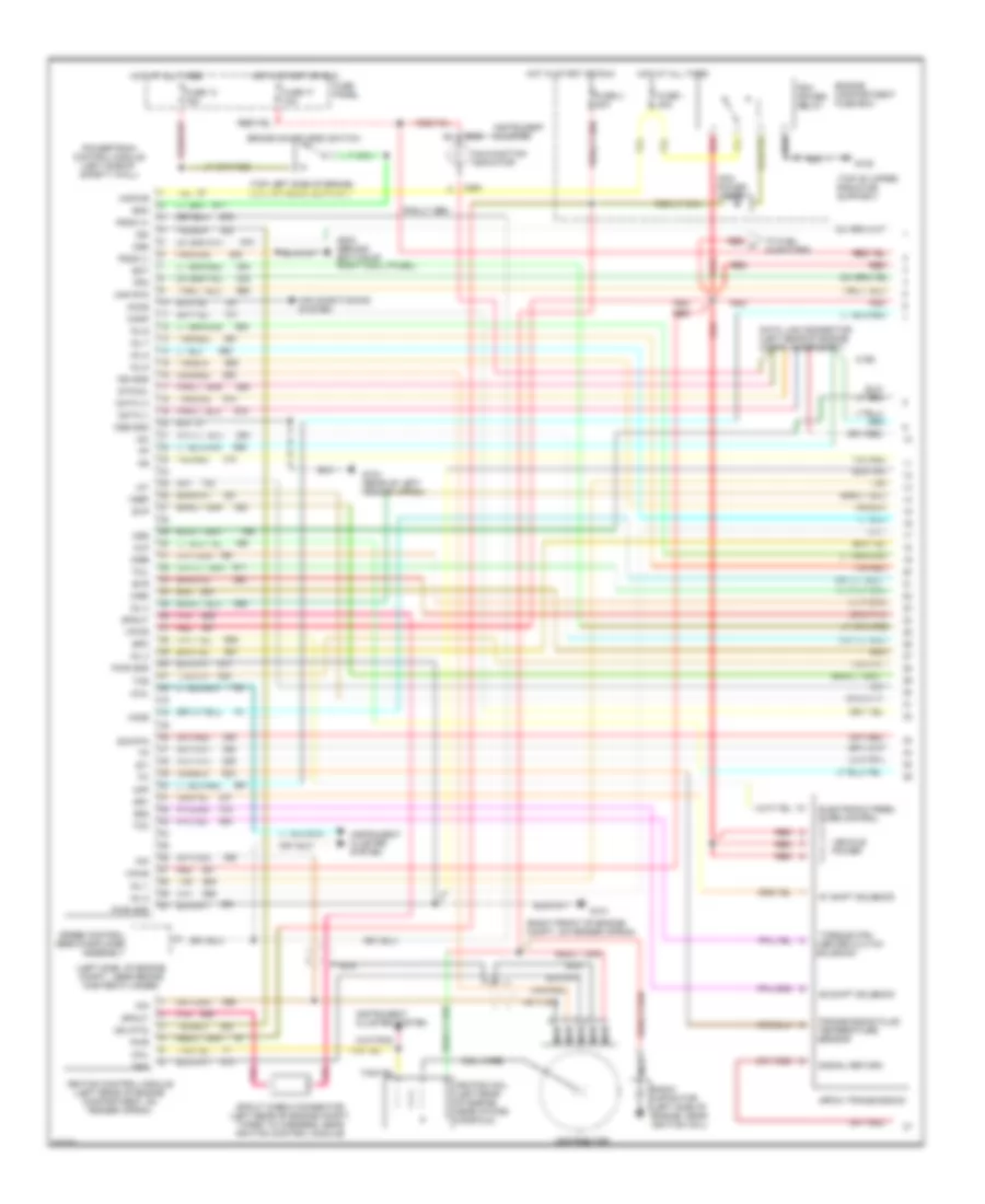
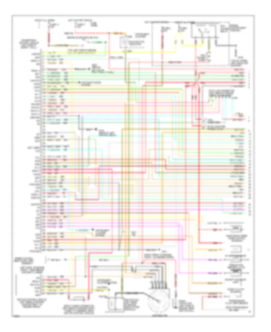
5.0L SFI, Engine Performance Wiring Diagrams, with 4R70W Transmission (1 of 2) for Ford Bronco 1995
List of elements for 5.0L SFI, Engine Performance Wiring Diagrams, with 4R70W Transmission (1 of 2) for Ford Bronco 1995:
- #1 shift solenoid
- #2 shift solenoid
- (left side of engine compt., near brake master cylinder)
- (right front of engine compt, on fender apron)
- (top left side of brake/ clutch pedal support)
- (top of upper radiator support)
- 4r70w transmission
- 4x4l
- Accs
- Air conditioning system
- Airb
- Aird
- Boo
- Brake on/off (boo) switch
- C198
- C250
- C251
- Canp
- Coil
- Coil wire
- Cse gnd
- Data (+)
- Data (-)
- Data link connector (left rear of engine compt, on bracket)
- Distributor
- Ect
- Electronic pres-
- Engine compartment fuse box
- Epc
- Evp
- Evr
- Fpm
- Fuse 13 15a
- Fuse 17 10a
- Fuse i 20a
- Fuse panel
- Fuse u 20a
- G101
- G104 (rear of left fender apron)
- G108
- G203 (behind bottom of right cowl panel)
- Gnd
- Ho2s
- Hot at all times
- Hot in start or run
- Iac
- Iat
- Idm
- Idm (fto)
- Ign gnd
- Ignition coil (left rear of engine, near intake manifold)
- Ignition control module (left rear of engine compartment, on fender apron)
- Inj 1
- Inj 2
- Inj 3
- Inj 4
- Inj 5
- Inj 6
- Inj 7
- Inj 8
- Instrument cluster
- Instrument cluster system
- Kapwr
- Maf
- Maf rtn
- Malfunction indicator
- Mlp
- Nca
- Oss
- Pcm
- Pcm power relay
- Pip
- Pnk
- Power diode
- Powertrain control module (left side of safety wall)
- Psom (+)
- Psom (-)
- Pwr
- Pwr gnd
- Radio capacitor (left side of engine, near ignition coil)
- Red
- Red a
- Sig rtn
- Signal return
- Solenoid
- Speed control servo/amplifier assembly
- Spout
- Spout check connector (left rear of engine compt, taped to harness, near ignition control module)
- Ss1
- Ss2
- Sti
- Sto/mil
- Sure control
- Tan
- Tan/red
- Tcc
- Tcil
- Tcs
- Tfi
- To fuel injectors
- Torque con- verter clutch
- Transmission fluid temperature sensor
- Vehicle power
- Vpwr
- Vref
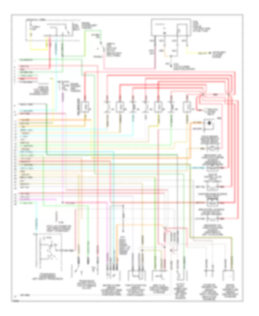
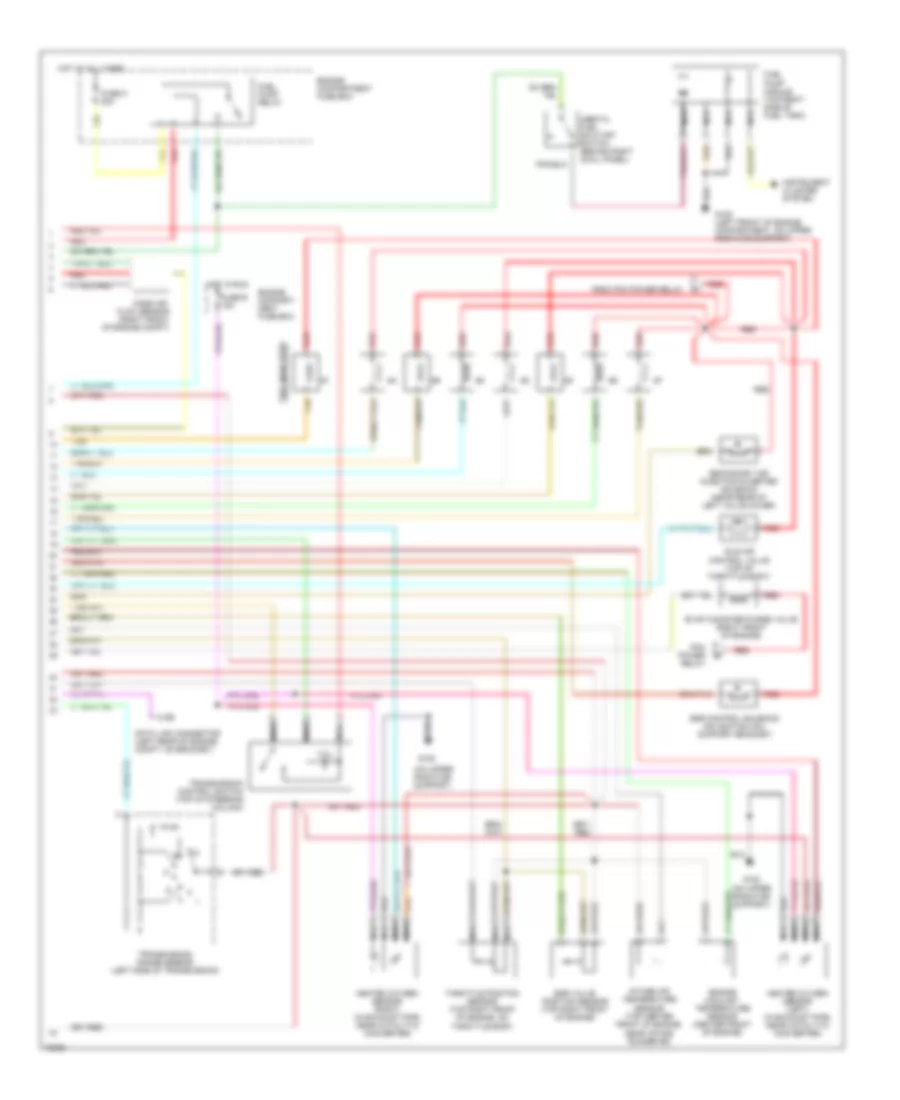
5.0L SFI, Engine Performance Wiring Diagrams, with 4R70W Transmission (2 of 2) for Ford Bronco 1995
List of elements for 5.0L SFI, Engine Performance Wiring Diagrams, with 4R70W Transmission (2 of 2) for Ford Bronco 1995:
- (right front engine compt, 0n front of fender apron)
- C199
- Canister purge solenoid (right front of engine)
- Data link connector (left rear of engine compt, on bracket)
- Egr control solenoid (on ignition coil support bracket)
- Egr valve position sensor (top right front of engine)
- Engine compart- ment fuse box
- Engine compartment fuse box
- Engine coolant temperature sensor (center front of engine)
- From pcm power relay
- Fuel injectors
- Fuel pump module (top right side of fuel tank)
- Fuel pump relay
- Fuse e 15a
- Fuse o 20a
- G101
- G108 (top of upper radiator support)
- Heated oxygen sensor (lower right rear of engine compt, in exhaust pipe)
- Hot at all times
- Hot in run
- Idle air control valve (top of throttle body)
- Inertia fuel shut-off switch (behind right cowl panel)
- Instrument cluster system
- Intake air temperature sensor (top center front of engine, near intake runner #6)
- Knock sensor (center rear of engine, behind intake manifold)
- Mass air flow sensor (right front of engine compt)
- Nca
- Output shaft speed (oss) sensor (left rear of tran- smission)
- Red
- Secondary air injection bypass solenoid (near rear of left valve cover)
- Secondary air injection diverter solenoid (near rear of left valve cover)
- Tan
- Tan/red
- Tcil
- Throttle position sensor (top right front of engine, on throttle body)
- Transmission control switch (top of steering column)
- Transmission range sensor (left side of transmission)
5.0L SFI, Engine Performance Wiring Diagrams, with E4OD Transmission (1 of 2) for Ford Bronco 1995
List of elements for 5.0L SFI, Engine Performance Wiring Diagrams, with E4OD Transmission (1 of 2) for Ford Bronco 1995:
- #1 shift solenoid
- #2 shift solenoid
- (left side of engine compt., near brake master cylinder)
- (right front of engine compt, on fender apron)
- (top left side of brake/ clutch pedal support)
- (top of upper left radiator support)
- 4x4l
- Accs
- Air conditioning system
- Airb
- Aird
- Boo
- Brake on/off (boo) switch
- C198
- C250
- C251
- Canp
- Ccs
- Coast clutch solenoid
- Coil
- Coil wire
- Cse gnd
- Data (+)
- Data (-)
- Distributor
- E40d transmission
- Ect
- Electronic pres- sure control solenoid
- Engine compartment fuse box
- Epc
- Evp
- Evr
- Fpm
- Fuse 13 15a
- Fuse 17 10a
- Fuse i 20a
- Fuse panel
- Fuse u 20a
- G101
- G104 (rear of left fender apron)
- G108
- G203 (behind bottom of right cowl panel)
- Gnd
- Ho2s
- Hot at all times
- Hot in start or run
- Iac
- Iat
- Idm
- Idm (fto)
- Ign gnd
- Ignition coil (left rear of engine, near intake manifold)
- Ignition control module (left rear of engine compartment, on fender apron)
- Inj 1
- Inj 2
- Inj 3
- Inj 4
- Inj 5
- Inj 6
- Inj 7
- Inj 8
- Instrument cluster
- Instrument cluster system
- Instrument clusters system
- Kapwr
- Maf
- Maf rtn
- Malfunction indicator
- Mlp
- Nca
- Pcm power diode
- Pcm power relay
- Pip
- Pnk
- Powertrain control module (left side of safety wall)
- Psom (+)
- Psom (-)
- Pwr
- Pwr gnd
- Radio capacitor (left side of engine, near ignition coil)
- Red
- Sig rtn
- Speed control servo/amplifier assembly
- Spout
- Spout check connector (left rear of engine compt, taped to harness, near ignition control module)
- Ss1
- Ss2
- Sti
- Sto/mil
- Tan
- Tan/red
- Tcc
- Tcil
- Tcs
- Tfi
- To fuel injectors
- Torque con- verter clutch solenoid
- Transmission fluid temp sensor
- Vip data link connector (left rear of engine compt, on bracket)
- Vpwr
- Vref
5.0L SFI, Engine Performance Wiring Diagrams, with E4OD Transmission (2 of 2) for Ford Bronco 1995
List of elements for 5.0L SFI, Engine Performance Wiring Diagrams, with E4OD Transmission (2 of 2) for Ford Bronco 1995:
- (right front of engine compt, 0n fender apron)
- Egr control solenoid (on ignition coil support bracket)
- Egr valve position sensor (top right front of engine)
- Engine compart- ment fuse box
- Engine compartment fuse box
- Engine coolant temperature sensor (center front of engine)
- Evap canister purge solenoid (right front of engine)
- From pcm power relay
- Fuel injectors
- Fuel pump module (top right side of fuel tank)
- Fuel pump relay
- Fuse e 15a
- Fuse o 20a
- G108
- G108 (left front of engine compartment, on upper radiator support)
- Heated oxygen sensor (in exhaust pipe, near catalytic converter)
- Hot at all times
- Hot in run
- Idle air control valve (top of throttle body)
- Inertia fuel shut-off switch (behind right cowl panel)
- Instrument cluster system
- Intake air temperature sensor (top center front of engine, near intake runner #6)
- Knock sensor (center rear of engine, behind intake manifold)
- Mass air flow sensor (right front of engine compt)
- Nca
- Red
- Secondary air injection bypass solenoid (near rear of left valve cover)
- Secondary air injection diverter solenoid (near rear of left valve cover)
- Tan
- Tan/red
- Tcil
- Throttle position sensor (top right front of engine, on throttle body)
- Transmission control switch (top of steering column)
- Transmission range sensor (left side of transmission)
- Vip data link connector (left rear of engine compt, on bracket)
5.8L
5.8L, Engine Performance Wiring Diagrams, California (1 of 2) for Ford Bronco 1995
List of elements for 5.8L, Engine Performance Wiring Diagrams, California (1 of 2) for Ford Bronco 1995:
- #1 shift solenoid
- #2 shift solenoid
- (left side of engine compt., near brake master cylinder)
- (not used)
- (right front of engine compt, on fender apron)
- (top left side of brake/ clutch pedal support)
- (top of upper left radiator support)
- 4x4l
- Accs
- Air conditioning system
- Aird
- Boo
- Brake on/off (boo) switch
- C198
- C250
- C251
- Canp
- Ccs
- Coast clutch solenoid
- Coil
- Coil wire
- Cse gnd
- Data (+)
- Data (-)
- Data link connector (left rear of engine compt, on bracket)
- Distributor
- E40d transmission
- Ect
- Electronic pres- sure control solenoid
- Engine compartment fuse box
- Epc
- Evap canister purge valve
- Evp
- Evr
- Fpm
- Fuel injectors
- Fuse 13 15a
- Fuse 17 10a
- Fuse i 20a
- Fuse panel
- Fuse u 20a
- G101
- G104 (rear of left fender apron)
- G108
- G203 (behind bottom of right cowl panel)
- Gnd
- Ho2s (l)
- Ho2s (r)
- Hot at all times
- Hot in start or run
- Iac
- Iat
- Idm
- Idm (fto)
- Ign gnd
- Ignition coil (left rear of engine, near intake manifold)
- Ignition control module (left rear of engine compartment, on fender apron)
- Inj 1
- Inj 2
- Inj 3
- Inj 4
- Inj 5
- Inj 6
- Inj 7
- Inj 8
- Instrument cluster
- Instrument cluster system
- Kapwr
- Maf
- Maf rtn
- Malfunction indicator
- Mlp
- Nca
- Pcm power diode
- Pcm power relay
- Pip
- Pnk
- Powertrain control module (left side of safety wall)
- Psom (+)
- Psom (-)
- Pwr
- Pwr gnd
- Radio capacitor (left side of engine, near ignition coil)
- Red
- Sig rtn
- Speed control servo/amplifier assembly
- Spout
- Spout check connector (left rear of engine compt, taped to harness, near ignition control module)
- Ss1
- Ss2
- Sti
- Sto/mil
- Tan
- Tan/red
- Tcc
- Tcil
- Tcs
- Tfi
- Torque con- verter clutch solenoid
- Transmission fluid temp sensor
- Vpwr
- Vref
5.8L, Engine Performance Wiring Diagrams, California (2 of 2) for Ford Bronco 1995
List of elements for 5.8L, Engine Performance Wiring Diagrams, California (2 of 2) for Ford Bronco 1995:
- (on upper radiator support)
- C199
- Data link connector (left rear of engine compt, on bracket)
- Egr control solenoid (on ignition coil support bracket)
- Egr valve position sensor (top right front of engine)
- Engine compart- ment fuse box
- Engine compartment fuse box
- Engine coolant temperature sensor (center front of engine)
- Evap canister purge valve (right front of engine)
- From pcm power relay
- Fuel injectors
- Fuel pump module (top right side of fuel tank)
- Fuel pump relay
- Fuse e 15a
- Fuse o 20a
- G108
- G108 (left front of engine compartment, on upper radiator support)
- G108 (on upper radiator support)
- Heated oxygen sensor (left) (in exhaust pipe, near catalytic converter)
- Heated oxygen sensor (right) (in exhaust pipe, near catalytic converter)
- Hot at all times
- Hot in run
- Idle air control valve (top of throttle body)
- Inertia fuel shut-off switch (behind right cowl panel)
- Instrument cluster system
- Intake air temperature sensor (top center front of engine, near intake runner #6)
- Mass air flow sensor (right front of engine compt)
- Nca
- Pcm power relay
- Red
- Secondary air injection diverter solenoid (near rear of left valve cover)
- Tan
- Tan/red
- Tcil
- Throttle position sensor (top right front of engine, on throttle body)
- Transmission control switch (top of steering column)
- Transmission range sensor (left side of transmission)
5.8L, Engine Performance Wiring Diagrams, Except California (1 of 2) for Ford Bronco 1995
List of elements for 5.8L, Engine Performance Wiring Diagrams, Except California (1 of 2) for Ford Bronco 1995:
- (fto) idm
- 4 x 4l
- Accs
- Acd
- Air conditioning system
- Airb
- Aird
- Boo
- Brake on/off switch (top left side of brake/clutch pedal support)
- C198
- C199
- C250
- C251
- Canp
- Ccs
- Coil
- Coil wire
- Cse gnd
- Data (+)
- Data (-)
- Data link connector (left rear of engine compt)
- Data link connector (left rear of engine compt, on bracket)
- Distributor
- Ecppwr/vpwr
- Ect
- Engine compartment fuse box
- Epc
- Epcpwr/vpwr
- Evp
- Evr
- Fpm
- Fuse 13 15a
- Fuse 17
- Fuse 17 10a
- Fuse i 20a
- Fuse panel
- Fuse u 20a
- G101 (right front of engine compt, on fender apron)
- G104 (rear of left fender apron)
- G108 (top of upper left radiator support)
- G203 (behind bottom of right cowl panel)
- Gnd
- Ho2s
- Ho2s gnd
- Hot at all times
- Hot in start or run
- Iac
- Iat
- Idm
- Ign gnd
- Ignition coil (near intake manifold)
- Ignition control module (left rear of engine compartment, on fender apron)
- Inj bank 1
- Inj bank 2
- Instrument cluster
- Instrument cluster system
- Kapwr
- Malfunction indicator
- Map
- Nca
- Pcm pin 32
- Pcm pin 41
- Pcm power diode
- Pcm power relay
- Pip
- Pnk
- Powertrain control module (left side of safety wall)
- Psom (+)
- Psom (-)
- Pwr
- Pwr gnd
- Radio capacitor (near ignition coil)
- Red
- Sig rtn
- Speed control servo amplifier assembly (near brake master cylinder)
- Spout
- Spout check connector (near ignition control module)
- Ss1
- Ss2
- Starting/ charging system (clutch pedal position switch)
- Sti
- Sto/mil
- Tan
- Tcc
- Tcil
- Tcs
- Tft
- Tr or cpp
- Transmission control switch
- Transmission range sensor
- Vehicle speed input
- Vref
- W/ e4od
- W/ e4od only
- W/ m/t
5.8L, Engine Performance Wiring Diagrams, Except California (2 of 2) for Ford Bronco 1995
List of elements for 5.8L, Engine Performance Wiring Diagrams, Except California (2 of 2) for Ford Bronco 1995:
- #1 shift solenoid
- #2 shift solenoid
- Canister purge solenoid (lower right side of engine compartment)
- Coast clutch solenoid
- E40d transmission
- Egr control solenoid (on ignition coil support bracket)
- Egr valve position sensor (top right front of engine)
- Electronic pressure control solenoid
- Engine compartment fuse box
- Engine compartment relay box
- Engine coolant temperature sensor (center front of engine)
- Fuel injectors
- Fuel pump relay
- Fuel pump/ fuel gauge sender (top right side of fuel tank)
- Fuse e 15a
- Fuse o 20a
- G101 (right front of engine compt, on fender apron)
- G108 (top of upper radiator support)
- Heated oxygen sensor (lower right rear of engine compt, in exhaust pipe)
- Hot at all times
- Hot in run
- Idle air control valve (top of throttle body)
- Inertia fuel shut-off switch (behind right cowl panel)
- Intake air temperature sensor (top center front of engine)
- Manifold absolute pressure sensor (top right side of safety wall)
- Nca
- Red
- Secondary air injection bypass solenoid (near rear of left valve cover)
- Secondary air injection diverter solenoid (near rear of left valve cover)
- Tan
- Throttle position sensor (top right front of engine)
- Torque converter clutch solenoid
- Trans- mission fluid temper- ature sensor

 Čeština
 Dansk
Dansk Deutsch
 English
 English
 Español
 Suomi
Suomi Français
 Français
 עברית
עברית Hrvatski
 Magyar
 Italiano
 日本語
日本語 한국어
한국어 Nederlands
 Polski
 Português
 Português
 Română
 Русский
 Slovenčina
 Slovenščina
 Svenska
 Türkçe
 中文 (中国)