STARTING/CHARGING
Charging Wiring Diagram for Mercury Tracer GS 1998
 https://portal-diagnostov.com/license.html
Automotive Electricians Portal FZCO
Automotive Electricians Portal FZCO
https://portal-diagnostov.com/license.html
https://portal-diagnostov.com/license.html
Automotive Electricians Portal FZCO
Automotive Electricians Portal FZCO
List of elements for Charging Wiring Diagram for Mercury Tracer GS 1998:
- (escort zx2)
- (escort/tracer)
- Battery
- C108
- C153
- C156
- C157
- C159
- C160
- C252
- C253
- C260
- Charge indicator
- Engine compartment fuse box
- Fuel injector fuse 30a
- G112 (near starter motor)
- Generator
- Ground distribution system
- Hot in run or start
- I/p fuse panel
- Instrument cluster
- Main fuse 100a
- Meter fuse 10a
- Nca
- Ohms
- S220
- Starter assembly
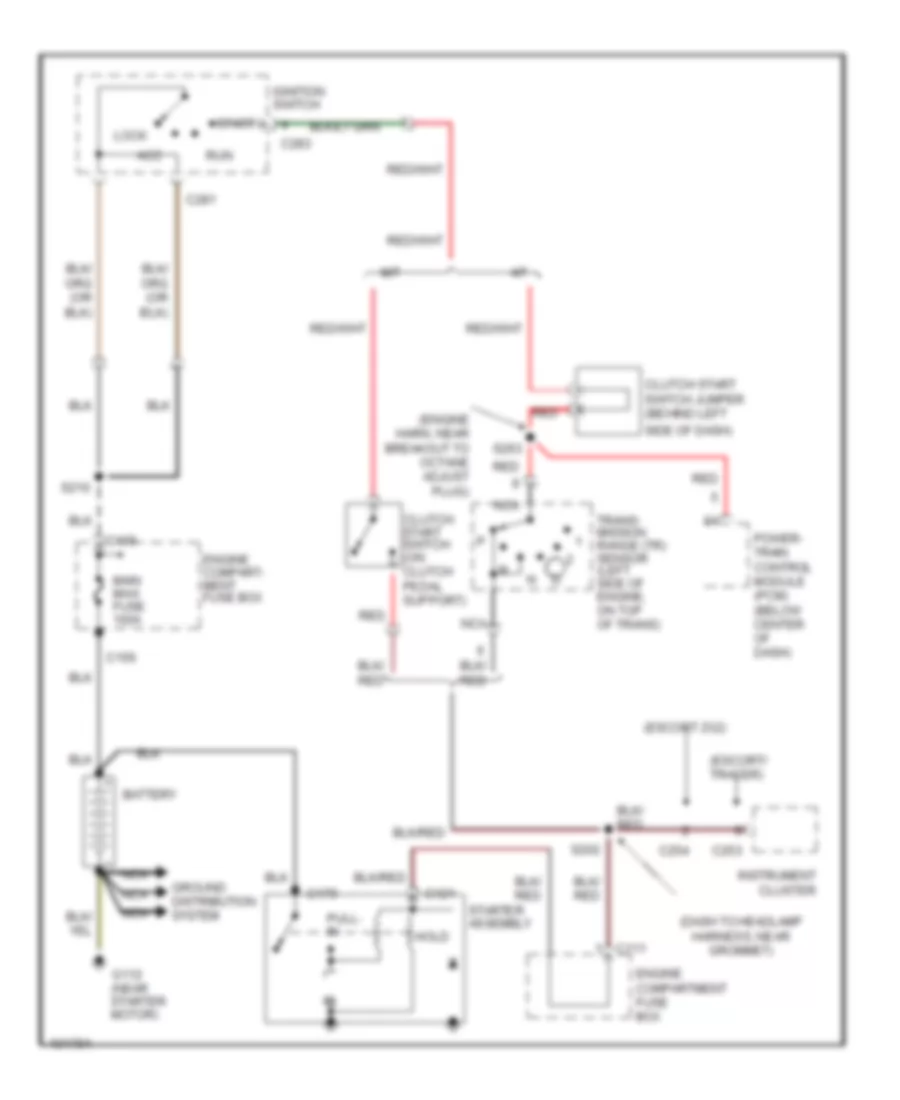
Starting Wiring Diagram for Mercury Tracer GS 1998
List of elements for Starting Wiring Diagram for Mercury Tracer GS 1998:
- (dash to headlamp harness, near grommet)
- (engine harn, near breakout to octane adjust plug)
- (escort zx2)
- (escort/ tracer)
- A/t
- Acc
- Battery
- C109
- C111
- C121
- C156
- C179
- C253
- C254
- C281
- C283
- Clutch start switch (on clutch pedal support)
- Clutch start switch jumper (behind left
- Engine compart- ment fuse box
- Engine compartment fuse box
- G112 (near starter motor)
- Ground distribution system
- Hold
- Ignition switch
- Instrument cluster
- Lock
- M/t
- Main maxi fuse 100a
- Nca
- Power- train control module (pcm) (below center of dash)
- Pull- in
- Red
- Run
- S202
- S210
- S263
- Side of dash)
- Start
- Starter assembly
- Trans- mission range (tr) sensor (left side of engine, on top of trans)

 Čeština
 Dansk
Dansk Deutsch
 English
 English
 Español
 Suomi
Suomi Français
 Français
 עברית
עברית Hrvatski
 Magyar
 Italiano
 日本語
日本語 한국어
한국어 Nederlands
 Polski
 Português
 Português
 Română
 Русский
 Slovenčina
 Slovenščina
 Svenska
 Türkçe
 中文 (中国)