WARNING SYSTEMS
Warning System Wiring Diagrams for Ford Probe GT 1995
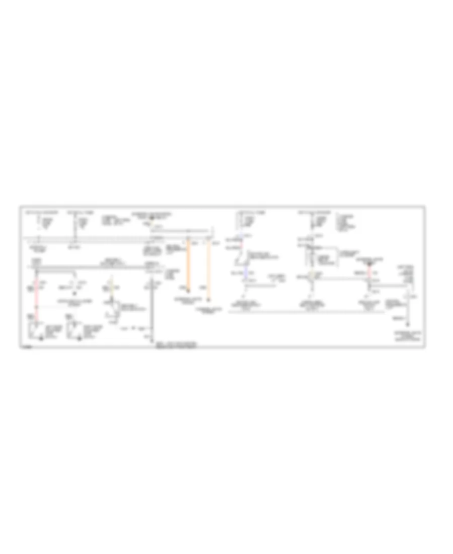
List of elements for Warning System Wiring Diagrams for Ford Probe GT 1995:
- (joint connector)
- (left side of i/p)
- (left side of i/p) interior fuse panel
- (not used)
- Backup lamp switch input
- Bat ign
- C201
- C213
- C214
- C215
- C240
- C241
- Central processing unit
- Door input
- Exterior lights system
- Exterior lights system (park lamp relay)
- Exterior lights system (backup lamps)
- Fasten belts indicator
- Fasten seat belt indicator output
- G300 (below left front seat)
- Ground
- Hot at all times
- Hot in run or start
- Ignition key reminder switch
- Ignition key reminder switch input
- Instrument cluster
- Instrument cluster system
- Interior fuse panel
- Interior fuse panel (left side of i/p)
- Interior lights system
- Left door courtesy lamp switch
- Meter fuse 15a
- Meter room 15a
- Nca
- Park and head lamps on circuit
- Power
- Right door courtesy lamp switch
- Room fuse 15a
- Seat belt buckle switch
- Seat belt buckled input
- Start/run
 Čeština
 Dansk
Dansk Deutsch
 English
 English
 Español
 Suomi
Suomi Français
 Français
 עברית
עברית Hrvatski
 Magyar
 Italiano
 日本語
日本語 한국어
한국어 Nederlands
 Polski
 Português
 Português
 Română
 Русский
 Slovenčina
 Slovenščina
 Svenska
 Türkçe
 中文 (中国)
 Ελληνικά