COOLING FAN
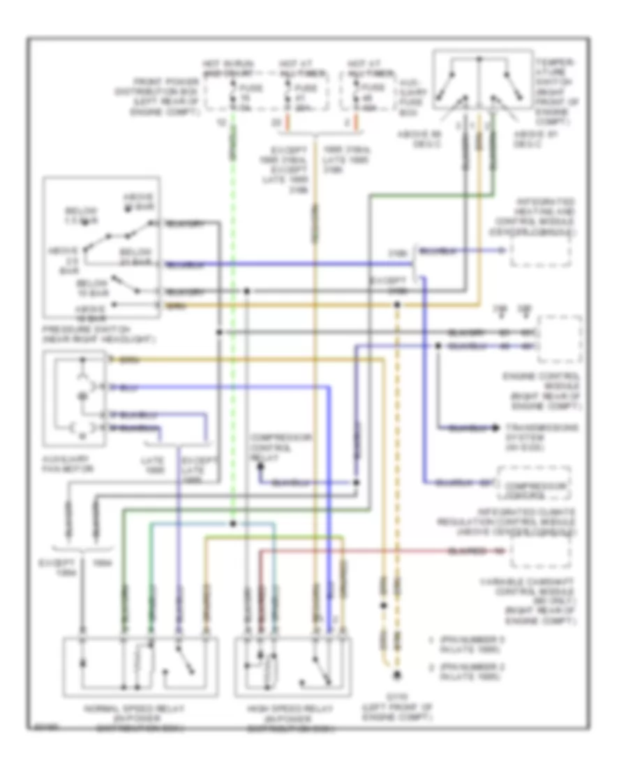
Auxiliary Cooling Fan Wiring Diagram for BMW 325is 1995
List of elements for Auxiliary Cooling Fan Wiring Diagram for BMW 325is 1995:
- (in power
- (pin number 2
- (pin number 5
- 1995 318i/s, late 1995 318ti
- 318ti
- Above 18 bar
- Above 2.6 bar
- Above 30 bar
- Above 91 deg c
- Above 99 deg c
- Aux- iliary fuse box
- Auxiliary fan motor
- Below 1.5 bar
- Below 15 bar
- Below 21 bar
- Compressor control
- Compressor control relay
- Distribution box)
- Engine control module (right rear of engine compt)
- Except
- Except 1995 318i/s, except late 1995 318ti
- Except 318ti
- Except late
- Fuse 30a
- Fuse 40a
- Fuse 5a
- G110 (left front of engine compt)
- High speed relay
- Hot at all times
- Hot in run and start front power distribution box (left rear of engine compt)
- In late 1995)
- Integrated climate regulation control module (above center console)
- Integrated heating and control module (center console)
- Late
- Normal speed relay
- Pressure switch (near right headlight)
- Temper- ature switch (right front of engine compt)
- Transmissions system (w/ egs)
- Variable camshaft control module (m3 only) (right rear of engine compt)
 Čeština
 Dansk
Dansk Deutsch
 English
 English
 Español
 Suomi
Suomi Français
 Français
 עברית
עברית Hrvatski
 Magyar
 Italiano
 日本語
日本語 한국어
한국어 Nederlands
 Polski
 Português
 Português
 Română
 Русский
 Slovenčina
 Slovenščina
 Svenska
 Türkçe
 中文 (中国)
 Ελληνικά