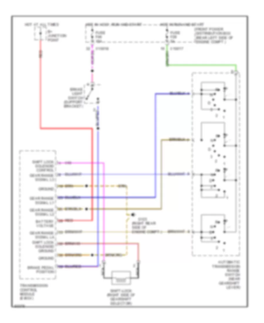
AUTOMOTIVE ELECTRICIANS PORTAL

SHIFT INTERLOCKS – BMW 325is 1995 – SYSTEM WIRING DIAGRAMS

SHIFT INTERLOCKS

Shift Interlock Wiring Diagram for BMW 325is 1995

Shift Interlock Wiring Diagram for BMW 325is 1995 https://portal-diagnostov.com/license.html
https://portal-diagnostov.com/license.html Automotive Electricians Portal FZCO Automotive Electricians Portal FZCO
Get access to all wiring diagrams of the carDownload PDF file

List of elements for Shift Interlock Wiring Diagram for BMW 325is 1995:

  • (right rear side of engine compt.)
  • Automatic transmission range switch (near gearshift lever)
  • B+ junction point
  • Battery voltage
  • Brake light switch (support bracket)
  • Brake pedal position
  • Front power distribution box (rear left side of engine compt.)
  • Fuse f28 5a
  • Fuse f46 15a
  • G123
  • Gear range signal l1
  • Gear range signal l2
  • Gear range signal l3
  • Gear range signal l4
  • Ground
  • Hot at all times
  • Hot in accy, run and start
  • Hot in run and start
  • Nca
  • Red
  • Shift lock solenoid control
  • Shift lock solenoid ground
  • Shift-lock (right side of gearshift selector)
  • Transmission control module (e-box)
  • X10017
  • X10018