
 Čeština
 Dansk
Dansk Deutsch
 English
 English
 Español
 Suomi
Suomi Français
 Français
 עברית
עברית Hrvatski
 Magyar
 Italiano
 日本語
日本語 한국어
한국어 Nederlands
 Polski
 Português
 Português
 Română
 Русский
 Slovenčina
 Slovenščina
 Svenska
 Türkçe
 中文 (中国)

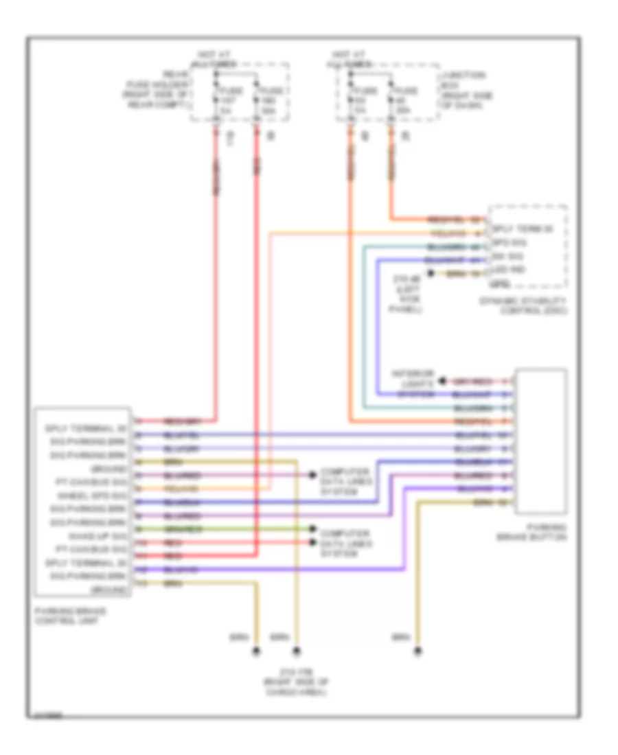
SHIFT INTERLOCK
Shift Interlock Wiring Diagram for BMW 535i GT 2010
List of elements for Shift Interlock Wiring Diagram for BMW 535i GT 2010:

WIPER/WASHERACTIVE BODYWORKSWARNING SYSTEMSANTI-THEFTCOMPUTER DATA LINESAIR CONDITIONINGCRUISE CONTROLANTI-LOCK BRAKESBODY CONTROL MODULESCOOLING FANDEFOGGERSENGINE PERFORMANCEELECTRONIC POWER STEERINGEXTERIOR LIGHTSELECTRONIC SUSPENSIONGROUND DISTRIBUTIONHEADLIGHTSHORNINTERIOR LIGHTSINSTRUMENT CLUSTERMEMORY SYSTEMSNAVIGATIONPOWER DISTRIBUTIONPOWER DOOR LOCKSPOWER SEATSPOWER MIRRORSPOWER WINDOWSPOWER TOP/SUNROOFSTARTING/CHARGINGSHIFT INTERLOCKTRUNK, TAILGATE, FUEL DOORRADIOSUPPLEMENTAL RESTRAINTSTRANSMISSION