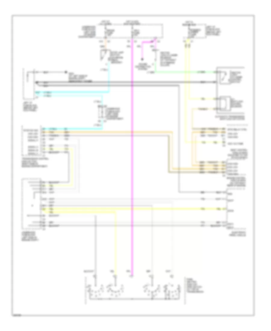
SHIFT INTERLOCK
Shift Interlock Wiring Diagram for Saturn L300 2005
List of elements for Shift Interlock Wiring Diagram for Saturn L300 2005:
- A/t shiftlock control solenoid
- A10
- A12
- Acc voltage
- Automatic transmission shiftlock actuator
- B1 btsi relay ctrl
- B11
- B12
- Body control module (bcm) (mounted to top of glove box)
- Brake fuse 15a
- Btsi/bcm/ mirror fuse 10a
- Can high
- Can low
- E11
- Electronic prndl module
- Engine control module (ecm) (on top right rear of engine)
- F10
- F11
- G304 (at left side of engine compt, near strut tower)
- Gnd
- Hot at all times
- Hot in acc run or start
- Hot in run or acc
- Ign 0 fuse 10a
- Ignition lock cylinder control switch
- Ignition lock cylinder solenoid (at top right of steering column)
- Left i/p fuse block (behind left kick panel)
- Park neutral position (pnp) switch (at top of transmission)
- Power distribution system
- Sig a
- Sig b
- Sig c
- Sig p
- Signal a
- Signal b
- Signal c
- Signal p
- Stop lamp switch (on brake pedal bracket)
- Stop sw sig
- Tan
- Transmission control module (tcm) (right side of engine compartment)
- Underhood fuse block (left side of engine compartment)
- Underhood fuse block (left side of engine compt)
 Čeština
 Dansk
Dansk Deutsch
 English
 English
 Español
 Suomi
Suomi Français
 Français
 עברית
עברית Hrvatski
 Magyar
 Italiano
 日本語
日本語 한국어
한국어 Nederlands
 Polski
 Português
 Português
 Română
 Русский
 Slovenčina
 Slovenščina
 Svenska
 Türkçe
 中文 (中国)
 Ελληνικά