ANTI-THEFT
Forced Entry Wiring Diagram for Saturn L300 2005

List of elements for Forced Entry Wiring Diagram for Saturn L300 2005:
- (behind right kick panel)
- A12
- Bcm/ cluster fuse 15a
- Body control module (bcm) (mounted to top of glove box)
- Body fuse 10a
- C3 f12
- Driver door jamb switch
- Driver door lock switch
- Drl relay ctrl
- E11
- Front passenger door lock switch
- G191
- Ground
- Ground distribution system
- Headlights system
- Horn relay ctrl
- Horns system
- Hot at all times
- Instrument panel cluster
- Left i/p fuse block (behind left kick panel)
- Left rear door jamb switch (at left "b" pillar)
- Lf door in
- Lock
- Lock sw in
- Other jamb sw
- Right front door jamb switch
- Right i/p fuse block
- Right i/p fuse block (behind right kick panel)
- Right rear door jamb switch (at right "b" pillar)
- Sec ind ctrl
- Security indicator
- Sp191 (at left side of engine compt, near strut tower)
- Underhood fuse block (left side of engine compt)
- Unlock
- Unlock sw in
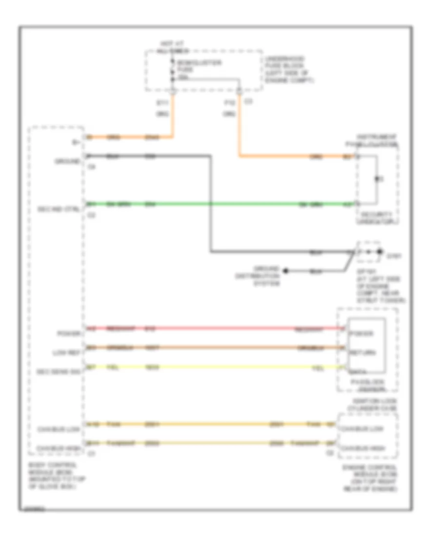
Passlock Wiring Diagram for Saturn L300 2005
List of elements for Passlock Wiring Diagram for Saturn L300 2005:
- A12
- B11
- Bcm/cluster fuse 15a
- Body control module (bcm) (mounted to top of glove box)
- Can bus high
- Can bus low
- Data
- E11
- Engine control module (ecm) (on top right rear of engine)
- F12
- G191
- Ground
- Ground distribution system
- Hot at all times
- Ignition lock cylinder case
- Instrument panel cluster
- Low ref
- Passlock sensor
- Power
- Return
- Sec ind ctrl
- Sec sens sig
- Security indicator
- Sp191 (at left side of engine compt, near strut tower)
- Tan
- Underhood fuse block (left side of engine compt)
 English