COOLING FAN
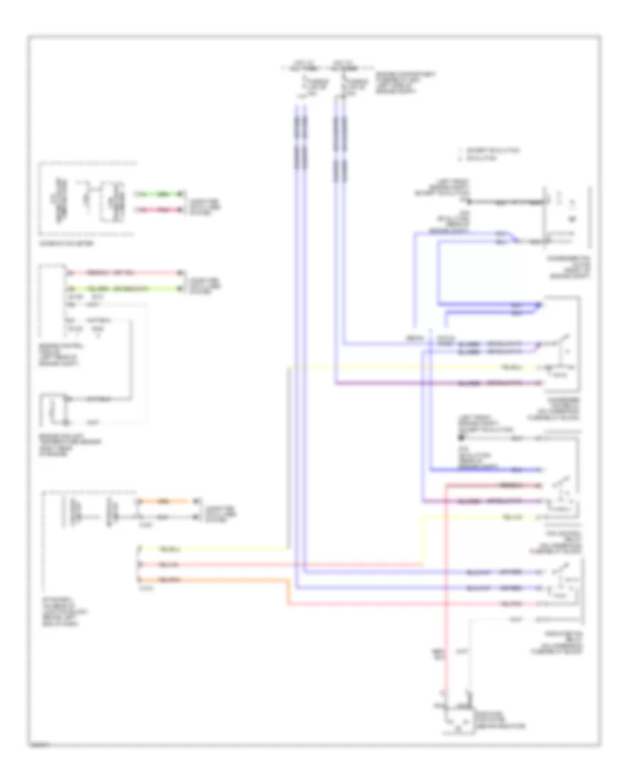
2.0L
2.0L, Cooling Fan Wiring Diagram for Mitsubishi Lancer DE 2010
 https://portal-diagnostov.com/license.html
Automotive Electricians Portal FZCO
Automotive Electricians Portal FZCO
https://portal-diagnostov.com/license.html
https://portal-diagnostov.com/license.html
Automotive Electricians Portal FZCO
Automotive Electricians Portal FZCO
List of elements for 2.0L, Cooling Fan Wiring Diagram for Mitsubishi Lancer DE 2010:
- (engine coolant lcd
- (left front engine compt) g17
- Analog interface circuit
- B-108
- B-109
- C-301
- C-312
- Can
- Can drive circuit
- Combination meter
- Computer data lines system
- Condenser fan motor (front of engine compt)
- Condenser fan relay (on underhood fuse/relay block)
- Cpu
- Engine compartment fuse/relay box (left side of engine compt)
- Engine control module (left rear of engine compt)
- Engine coolant temperature sensor (on rear of cylinder head)
- Etacs-ecu (on rear of junction block, behind left end of dash)
- Fan control relay (on underhood fuse/relay block)
- Fusible link 28 30a
- Fusible link 29 40a
- Hot at all times
- Interface circuit
- Nca
- Pnk
- Radiator fan motor (behind radiator)
- Radiator fan relay (on underhood fuse/relay block)
- Red
- Temperature)
- Transceiver circuit
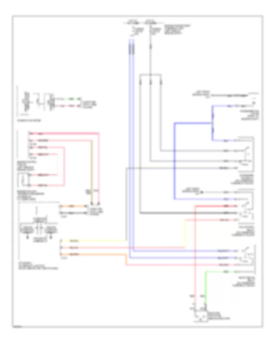
2.0L TURBO
2.0L Turbo, Cooling Fan Wiring Diagram for Mitsubishi Lancer DE 2010
List of elements for 2.0L Turbo, Cooling Fan Wiring Diagram for Mitsubishi Lancer DE 2010:
- (engine coolant lcd
- (left front engine compt) (except evolution) g17
- (or red)
- B-09
- B-10
- B-108
- B-109
- C-301
- C-312
- Can
- Can drive circuit
- Circuit interface
- Combination meter
- Computer data lines system
- Condenser fan motor (front of engine compt)
- Condenser fan relay (on underhood fuse/relay block)
- Cpu
- Engine compartment fuse/relay box (left side of engine compt)
- Engine control module (left rear of engine compt)
- Engine coolant temperature sensor (right rear of engine)
- Etacs-ecu (on rear of junction block, behind left end of dash)
- Evolution
- Except evolution
- Fan control relay (on underhood fuse/relay block)
- Fusible link 28 30a
- Fusible link 29 40a
- G16 (evolution) (rear of engine compt)
- Hatch- back
- Hot at all times
- Nca
- Pnk
- Radiator fan motor (behind radiator)
- Radiator fan relay (on underhood fuse/relay block)
- Sedan
- Temperature)
- Transceiver circuit
2.4L
2.4L, Cooling Fan Wiring Diagram for Mitsubishi Lancer DE 2010
List of elements for 2.4L, Cooling Fan Wiring Diagram for Mitsubishi Lancer DE 2010:
- (engine coolant lcd
- (left front engine compt) g17
- Analog interface circuit
- B-108
- B-109
- C-301
- C-312
- Can
- Can drive circuit
- Combination meter
- Computer data lines system
- Condenser fan motor (front of engine compt)
- Condenser fan relay (on underhood fuse/relay block)
- Cpu
- Engine compartment fuse/relay box (left side of engine compt)
- Engine control module (left rear of engine compt)
- Engine coolant temperature sensor (on rear of cylinder head)
- Etacs-ecu (on rear of junction block, behind left end of dash)
- Fan control relay (on underhood fuse/relay block)
- Fusible link 28 30a
- Fusible link 29 40a
- Hot at all times
- Interface circuit
- Nca
- Pnk
- Radiator fan motor (behind radiator)
- Radiator fan relay (on underhood fuse/relay block)
- Red
- Temperature)
- Transceiver circuit

 Čeština
 Dansk
Dansk Deutsch
 English
 English
 Español
 Suomi
Suomi Français
 Français
 עברית
עברית Hrvatski
 Magyar
 Italiano
 日本語
日本語 한국어
한국어 Nederlands
 Polski
 Português
 Português
 Română
 Русский
 Slovenčina
 Slovenščina
 Svenska
 Türkçe
 中文 (中国)