CRUISE CONTROL
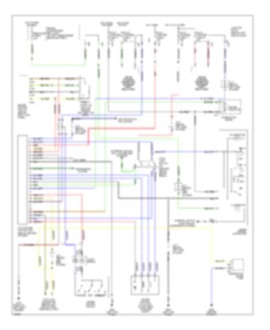
Cruise Control Wiring Diagram for Mitsubishi Montero 2000
List of elements for Cruise Control Wiring Diagram for Mitsubishi Montero 2000:
- (behind center of dash)
- (behind left side of dash)
- (not used)
- (on bracket, above brake pedal)
- Auto cruise control ecu
- C04
- C06
- C12
- C149
- C150
- C80
- C81
- C93
- C94
- C97
- Cancel
- Clock spring
- Combination meter
- Combination meter (vss)
- Cruise control actuator (in left rear of engine compt)
- Cruise control main switch
- Cruise control switch
- Cruise indicator
- Data link connector (behind left side of dash, near relay box)
- Dedicated fuse 5 10a
- Engine compartment relay box (on left inner fender behind battery)
- Engine control module (behind right kick panel)
- Exterior lights & anti-lock brakes systems
- G100 (front of left front fender)
- G200 (left kick panel)
- G206 (center of dash)
- Hot at all times
- Hot in acc
- Hot in park or head
- Hot in run
- Idle
- Ignition switch pin 5 (start)
- Illumination
- Interior lights & electronics suspension systems
- Iod or iod or storage storage connector connector (in engine (in engine compt compt relay box) relay box)
- J/c 1 (behind left side of dash)
- J/c 2 (behind left side of dash)
- J/c 3 (behind left side of dash)
- Junction block
- Multi- purpose fuse 11 10a
- Multi- purpose fuse 17 15a
- Multi- purpose fuse 19 10a
- Multi- purpose fuse 2 10a
- Multi- purpose fuse 4 10a
- Off
- On indicator
- Or run
- Or start
- Red
- Resume
- Set
- Stop- light switch
- Throttle position sensor (on throttle body)
- Transmission system
 Čeština
 Dansk
Dansk Deutsch
 English
 English
 Español
 Suomi
Suomi Français
 Français
 עברית
עברית Hrvatski
 Magyar
 Italiano
 日本語
日本語 한국어
한국어 Nederlands
 Polski
 Português
 Português
 Română
 Русский
 Slovenčina
 Slovenščina
 Svenska
 Türkçe
 中文 (中国)
 Ελληνικά